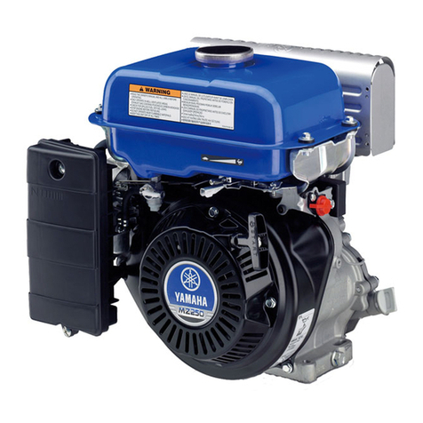
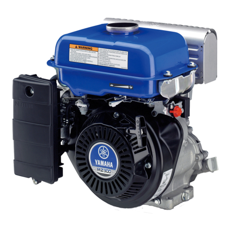
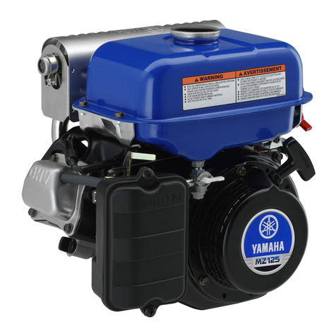
Yamaha MZ125 User manual

MZ125/MZ125R
MZ175/MZ175R
MZ200/MZ200R
SUPPLEMENTARY
SERVICE MANUAL
7NN-F8197-E1


FOREWORD
This Supplementary Service Manual has been
prepared to introduce new service and new
data for the MZ125/MZ125R, MZ175/MZ175R,
MZ200/MZ200R.
For complete information on service proce-
dures, it is necessary to use this Supplementary
Service Manual together with following manual:
TIP
This manual was written by the YAMAHA
MOTOR POWERED PRODUCTS CO., LTD.
primarily for use by Yamaha dealers and their
qualified mechanics. It is not possible to put an
entire mechanic’s education into one manual,
so it is assumed that persons using this book
to perform maintenance and repairs on
Yamaha Multi-Purpose Engine have a basic
understanding of the mechanical precepts and
procedures inherent to Multi-Purpose Engine
repair technology. Without such knowledge,
attempted repairs or service to this model may
render it unfit for use and/or unsafe.
YAMAHA MOTOR POWERED PRODUCTS
CO., Ltd. is continually striving to further
improve all models manufactured by Yamaha.
Modifications and significant changes in speci-
fications or procedures will be forwarded to all
Authorized Yamaha dealers and will, where
applicable, appear in future editions of this
manual.
MZ125/MZ125R, MZ175/MZ175R,
MZ200/MZ200R
SUPPLEMENTARY SERVICE MANUAL
©2010 by YAMAHA MOTOR POWERED
PRODUCTS CO., LTD.
1st Edition, December 2010
All rights reserved. Any reprinting or
unauthorized use without the written
permission of YAMAHA MOTOR
POWERED PRODUCTS CO., LTD.
is expressly prohibited.
MZ125, MZ175
SERVICE MANUAL:
7NN-28197-E0 (310083)
HOW TO USE THIS MANUAL
PARTICULARLY IMPORTANT
INFORMATION
Particularly important information is distin-
guished in this manual by the following
notations.
This is the safety alert symbol. It is used to
alert you to potential personal injury haz-
ards. Obey all safety messages that follow
this symbol to avoid possible injury or
death.
WARNING
A WARNING indicates a hazardous situa-
tion which, if not avoided, could result in
death or serious injury.
NOTICE
A NOTICE indicates special precautions
that must be taken to avoid damage to the
machine or other property.
TIP
A TIP provides key information to make
procedures easier or clearer.
MANUAL FORMAT
The procedures in this manual are organized
in a sequential, step-by-step format. The infor-
mation has been compiled to provide the
mechanic with an easy to read, handy refer-
ence that contains comprehensive explana-
tions of all disassembly, repair, assembly, and
inspection operations.
In this revised format, the condition of a faulty
component will precede an arrow symbol and
the course of action required will follow the
symbol, e.g.,
9 Bearings
Pitting/damage → Replace.
EXPLODED DIAGRAM
Each chapter provides exploded diagrams
before each disassembly section for ease in
identifying the correct disassembly and
assembly procedures.
ILLUSTRATED SYMBOLS
(Refer to the illustration)
SYMBOL DEFINITION SYMBOL DEFINITION
General information Wear limit, clearance
Periodic inspections and
adjustments Engine speed
Engine Electrical data
Electrical
M
Molybdenum disulfide oil
Specifications
E
Engine oil
Special tool LS Lithium-soap base grease
Filling fluid LT Apply locking agent (LOCTITE®).
Lubricant Replace the part with a new one.
T
R
.
.
Tightening torque MMolybdenum disulfide grease

INDEX
GENERAL INFORMATION GEN
INFO
PERIODIC INSPECTIONS
AND ADJUSTMENTS INSP
ADJ
SPECIFICATIONS SPEC
1
2
3

CHAPTER 1.
GENERAL INFORMATION
MACHINE IDENTIFICATION .....................1-1
SERIAL NUMBER ................................1-1
STARTING SERIAL NUMBER ..................1-1
DIMENSION CHART (STANDARD
MODEL, MZ125/MZ175/MZ200) ................1-2
DIMENSION CHART (REDUCTION
MODEL, MZ125R/MZ175R/MZ200R) ........1-3
MOUNTING BASE DIMENSION ...............1-3
CHAPTER 2.
PERIODIC INSPECTIONS AND
ADJUSTMENTS
INTRODUCTION ........................................2-1
PERIODIC MAINTENANCE/
LUBRICATION INTERVALS ......................2-1
CHAPTER 3.
SPECIFICATIONS
GENERAL SPECIFICATIONS ...................3-1
MAINTENANCE SPECIFICATIONS ..........3-3
ENGINE ................................................3-3
ELECTRICAL ........................................3-6
TIGHTENING TORQUE .............................3-7
GENERAL TORQUE SPECIFICATIONS ...3-7

1-1
GEN
INFO
1
2
3
GENERAL INFORMATION
MACHINE IDENTIFICATION
SERIAL NUMBER
The serial number 1 is printed on the label 2
affixed to the position 3 of the Multi-Purpose
Engine as shown in the illustration.
TIP
The first four digits identifies a model, and
the remaining digits indicates a production
number.
STARTING SERIAL NUMBER
Model Code Serial number
A
MZ125 A2B
MZ125 B1T
MZ125 B2B
7CL1
7CL2
7CL2
7CL1-1000101
7CL2-1000101
7CL2-2000101
MZ125 K2-60
MZ125 K2-50
MZ125 Cr2B
7CLB
7CLB
7CLF
7CLB-1000101
7CLB-2000101
7CLF-1000101
B
MZ175 A1 7CN1 7CN1-1000101
MZ175 A2B 7CN1 7CN1-2000101
MZ175 A2C 7CN1 7CN1-3000101
MZ175 B1T 7CN2 7CN2-1000101
MZ175 B2B 7CN2 7CN2-2000101
MZ175 B2C 7CN2 7CN2-3000101
MZ175 B2BK 7CN2 7CN2-4000101
MZ175 E2 7CN5 7CN5-1000101
MZ175 L2U-EF 7CNC 7CNC-3000101
MZ175 K2U 7CNB 7CNB-3000101
MZ175 Br1
MZ175 Br2B
7CNF
7CNF
7CNF-1000101
7CNF-2000101
CMZ200 B1AT
MZ200 Br1AT
7DH1
7DHF
7DH1-1000101
7DHF-1000101
TIP
Designs and specifications are subject to
change without notice.
7CL Ð
1
7CN Ð
1
7DH Ð
1
A
B
C
MACHINE IDENTIFICATION/STARTING SERIAL NUMBER
1

1-2
GEN
INFO
DIMENSION CHART (STANDARD MODEL, MZ125/MZ175/MZ200)
Unit: mm
Model (Code) PTO shaft dimensions (Type) Mounting face dimensions (Type)
MZ125 A2B (7CL1)
MZ175 A1 (7CN1)
MZ175 A2B (7CN1)
MZ175 A2C (7CN1)
5/16-24UNF-2B*
61.5
58.3
17
47.6
+ 0.048
0
4.72
0
− 0.13
16.36
0
− 0.021
¯19.05
(A)
MZ175 E2 (7CN5)
3/4-16UNF-2A*
0
− 0.021
¯19.05
22.5
58.3
61.5
45˚
92.075
65.1
DEPTH 14
45˚
5/16-24UNF-2B*
(E)
MZ125 K2-60 (7CLB)
MZ125 K2-50 (7CLB)
MZ175 K2U (7CNB)
5/16-24UNF*
0
− 0.25
¯19.177
0
− 0.013
¯19.843
16 14.3
52.3
71.8
Taper 3/16
(K) (B)
MZ125 B1T (7CL2)
MZ125 B2B (7CL2)
MZ175 B1T (7CN2)
MZ175 B2B (7CN2)
MZ175 B2C (7CN2)
MZ175 B2BK (7CN2)
MZ200 B1AT (7DH1)
M8 1.25 − 2
50
53
16
+ 0.05
0
5
0
− 0.1
17
0
− 0.021
Ø20
34
(B)
45˚
92.075
65.1
DEPTH 14
45˚
M8 1.25
MZ175 L2U-EF
(7CNC)
Ø19.3
Ø19
Ø8.5
22
26.5
25 10.5
35.5
Taper 1/5
M8 1.25 − 2
(L) (A)
*: UNF; Unified fine thread (Unit: in)
DIMENSION CHART (STANDARD MODEL, MZ125/
MZ175/MZ200)

1-3
GEN
INFO
DIMENSION CHART (REDUCTION MODEL, MZ125R/MZ175R/MZ200R)
Unit: mm
Model (Code) PTO shaft dimensions (Type) Mounting face dimensions
MZ125 Cr2B (7CLF)
M8 1.25 − 2
− 0.018
0
¯18
16
50
53
34
− 1
0
15
0
+ 0.030
5
(Cr)
MZ175 Br1 (7CNF)
MZ175 Br2B (7CNF)
MZ200 Br1AT (7DHF)
M8 1.25 − 2
− 0.021
0
¯20
16
50
53
34
− 0.1
0
17
0
+ 0.030
554
DEPTH 13
M8 1.25
54
(Br)
*: UNF; Unified fine thread (Unit: in)
MOUNTING BASE DIMENSION
(Unit: mm)
119.5 Engine center line
75
539.5 35.5
29.9132.1
9666
162
2-Ø92-R4.5
81.5
1/2 Reduction model
PTO shaft center
PTO shaft center
(PTO height: 160 mm)
Standard (Direct) model
DIMENSION CHART (REDUCTION MODEL, MZ125R/
MZ175R/MZ200R)/MOUNTING BASE DIMENSION

1-4
GEN
INFO

2-1
INSP
ADJ
INTRODUCTION/
PERIODIC MAINTENANCE/LUBRICATION INTERVALS
PERIODIC INSPECTIONS AND ADJUSTMENTS
INTRODUCTION
This chapter includes all information necessary to perform recommended inspections and adjust-
ments. These preventive maintenance procedures, if followed, will ensure more reliable machine
operation and a longer service life. The need for costly overhaul work will be greatly reduced. This
information applies to machines already in service as well as new machines that are being pre-
pared for sale. All service technicians should be familiar with this entire chapter.
PERIODIC MAINTENANCE/LUBRICATION INTERVALS
No. Item Remarks
Pre-Opera-
tion check
(daily)
Initial Every
1 month
or 20 hr
3 months
or 50 hr
6 months
or 100 hr
12 months
or 300 hr
1. Spark plug
Check condition,
adjust gap and clean.
Replace if necessary.
8
2. Valve
clearance
Check and adjust
when engine is cold. 8
3.
Crankcase
breather
system
Check breather hose
for cracks or damage.
Replace if necessary.
8
4. Idle speed Check and adjust
engine idle speed. 8
5. Exhaust
system
Check for leakage.
Retighten or replace
gasket if necessary.
8
Check spark arrester.
Clean/replace if
necessary.
8
6. Engine oil Check oil level. 8
Replace. 8 8
7. Air filter Clean. Replace if
necessary.
8
8. Fuel filter
Clean fuel petcock
and fuel tank filter.
Replace if necessary.
8
9. Fuel line
Check fuel hose for
cracks or damage.
Replace if necessary.
8
10. Choke lever Check choke
operation.
8
11. Cooling
system
Check for fan
damage.
8
12. Starting
system
Check recoil starter
operation. 8
13. Muffler screen Clean. Replace if
necessary.
8
14.
Decarbonization
More frequency if
necessary. 8
15. Fittings/
fasteners
Check all fittings and
fasteners. Correct if
necessary.
8
2

2-2
INSP
ADJ

3-1
SPEC
GENERAL SPECIFICATIONS
Model name MZ125 MZ125R MZ175 MZ175R
Model code number 7CL 7CN
Dimensions:
Overall length mm (in) 323 (12.7) 353 (13.9) 315 (12.4) 353 (13.9)
Overall width mm (in) 352 (13.9)
Overall height mm (in) 370 (14.6)
Weight kgf (lbf) 15.5 (34) 16.5 (36) 16.0 (35) 17 (38)
Engine:
Type Air cooled 4-stroke gasoline OHV
Cylinder arrangement Single cylinder
Displacement L (cm3) 0.123 (123) 0.171 (171)
Bore × Stroke mm (in) 56.0 × 50.0 (2.20 × 1.97) 66.0 × 50.0 (2.60 × 1.97)
Compression ratio 8.3 : 1 8.5 : 1
Rated output 2.2 (3.0) / 3600 2.2 (3.0) / 1800 3.3 (4.5) / 3600 3.3 (4.5) / 1800
kW (PS) / r/min
Rated engine speed r/min 3600 1800 3600 1800
Starting method Recoil starter
Ignition system TCI
Ignition timing BTDC 23° ± 3°
Spark plug type BPR4ES (NGK)
Spark plug gap mm (in) 0.7–0.8 (0.028–0.031)
Fuel tank:
Recommended fuel Unleaded regular gasoline
Fuel tank capacity
L (US gal, lmp gal)
4.5 (1.18, 0.99)
Engine oil:
Engine oil quantity 0.6 (0.63, 0.53)
L (US qt, lmp qt)
Recommended engine oil
type
YAMALUBE
SAE 10W-30 or 10W-40
-20 -10 0 10 20 30 40 50 °C
0 10 30 50 70 90 110 130 °F
SAE 10W-40
SAE 10W-30
Recommended engine oil
grade
API service SE type or higher
JASO standard MA
3
SPECIFICATIONS
GENERAL SPECIFICATIONS

3-2
SPEC
Model name MZ200 MZ200R
Model code number 7DH
Dimensions:
Overall length mm (in) 331 (13.0) 369 (14.5)
Overall width mm (in) 362 (14.3)
Overall height mm (in) 370 (14.6)
Weight kgf (lbf) 17.7 (39) 18.7 (41)
Engine:
Type Air cooled 4-stroke gasoline OHV
Cylinder arrangement Single cylinder
Displacement L (cm3) 0.192 (192)
Bore × Stroke mm (in) 70.0 × 50.0 (2.76 × 1.97)
Compression ratio 8.4 : 1
Rated out put 3.8 (5.2) / 3600 3.8 (5.2) / 1800
kW (PS) / r/min
Rated engine speed r/min 3600 1800
Starting method Recoil starter
Ignition system TCI
Ignition timing BTDC 28° ± 3°
Spark plug type BPR4ES (NGK)
Spark plug gap mm (in) 0.7–0.8 (0.028–0.031)
Fuel tank:
Recommended fuel Unleaded regular gasoline
Fuel tank capacity 4.5 (1.18, 0.99)
L (US gal, lmp gal)
Engine oil:
Engine oil quantity 0.6 (0.63, 0.53)
L (US qt, lmp qt)
Recommended engine oil
type
YAMALUBE
SAE 10W-30 or 10W-40
-20 -10 0 10 20 30 40 50 °C
0 10 30 50 70 90 110 130 °F
SAE 10W-40
SAE 10W-30
Recommended engine oil
grade
API service SE type or higher
JASO standard MA
GENERAL SPECIFICATIONS

3-3
SPEC
Model name MZ125 MZ125R MZ175 MZ175R MZ200 MZ200R
Model code number 7CL 7CN 7DH
Piston: mm (in)
Piston clearance 0.015–0.040 (0.0006–0.0016) 0.031–0.045
(0.0012–0.0018)
Piston skirt “D”
55.968–55.997
(2.2035–2.2046)
65.968–65.997
(2.5971–2.5983)
69.961–65.982
(2.7544–2.5977)
<Limit> 55.9 (2.2008) 65.9 (2.5945) 69.9 (2.7520)
Measuring point “H” 5.0 (0.197) 10.0 (0.394)
Oversize 1st 56.25 (2.215) 66.25 (2.608) 70.25 (2.766)
2nd 56.50 (2.224) 66.50 (2.618) 70.50 (2.776)
Piston pin hole inside
diameter
16.002–16.013 (0.6300–0.6304)
<Limit> 16.05 (0.63)
Piston pin: mm (in)
Piston pin diameter 15.995–16.000 (0.6297–0.6299)
<Limit> 15.95 (0.628)
Piston ring: mm (in)
Top ring
Type Barrel face
Dimensions “B × T” 1.5 × 2.4
(0.059 × 0.094)
1.5 × 2.7 (0.059 × 0.106)
End gap 0.20–0.40 (0.008–0.016)
<Limit> 0.9 (0.0354)
Side clearance 0.04–0.08 (0.0016–0.0031)
<Limit> 0.1 (0.0039)
2nd ring
Type Taper
Dimensions “B × T” 1.5 × 2.4 1.5 × 2.7 (0.059 × 0.106)
(0.059 × 0.094)
End gap 0.20–0.40 (0.008–0.016)
<Limit> 0.9 (0.0354)
Side clearance 0.02–0.06 (0.0008–0.0024)
<Limit> 0.1 (0.0039)
Oil ring
Type 3-piece type
Dimensions “B × T” 2.5 × 2.5 2.5 × 2.8 (0.098 × 0.110)
(0.098 × 0.098)
End gap 0.20–0.70 (0.008–0.028)
<Limit> 0.9 (0.0354)
MAINTENANCE SPECIFICATIONS
ENGINE
MAINTENANCE SPECIFICATIONS
D
H
B
T

3-4
SPEC
Model name MZ125 MZ125R MZ175 MZ175R MZ200 MZ200R
Model code number 7CL 7CN 7DH
Cylinder: mm (in)
Inside diameter “D” 56.005–56.015
(2.2049–2.2053)
66.005–66.015
(2.5986–2.5990)
70.000–70.020
(2.7559–2.7567)
Warpage limit 0.05 (0.002)
Cylinder head: mm (in)
Warpage limit 0.1 (0.004)
Crankshaft: mm (in)
Big end side clearance “A” 0.2–0.6 (0.008–0.024)
<Limit> 0.8 (0.03)
Runout “B” 0.02 (0.0008)
<Limit> 0.04 (0.0016)
Crank pin outside diameter
“C”
27.969–27.984 (1.1011–1.1017)
<Limit> 27.9 (1.098)
Connecting rod: mm (in)
Small end diameter “A” 16.006–16.020 (0.6302–0.6307)
Big end diameter “B” 28.000–28.015 (1.1024–1.1030)
Oil clearance 0.016–0.046 (0.0006–0.0018)
<Limit> 0.1 (0.0039)
Camshaft: mm (in)
Cam dimension
“A” IN 26.9 (1.059)
“A” EX 26.68 (1.050)
“B” IN 22.0 (0.866)
“B” EX 22.0 (0.866)
Camshaft journal diameter 14.965–14.990 (0.5892–0.5902)
MAINTENANCE SPECIFICATIONS
BB
A
C
B
A

3-5
SPEC
Model name MZ125 MZ125R MZ175 MZ175R MZ200 MZ200R
Model code number 7CL 7CN 7DH
Valve: mm (in)
Valve dimension
Head diameter
“A”
IN 21.0 (0.83) 24.0 (0.94) 26.0 (1.02)
EX 19.0 (0.75) 22.0 (0.87)
Stem diameter
“B”
IN 5.5 (0.22)
EX 5.5 (0.22)
Stem length “C”
IN 64.5 (2.54) 65.9 (2.59)
EX 64.5 (2.54) 66.2 (2.61)
Valve face contact
width “D”
IN 0.7 (0.028)
EX 0.7 (0.028)
<Limit>
IN 1.7 (0.067)
EX 1.7 (0.067)
“θ” 90°
Valve guide
Guide inside diameter
IN 5.5 (0.22)
EX 5.5 (0.22)
Stem to guide clearance
IN 0.04–0.06 (0.0016–0.0024)
EX 0.06–0.08 (0.0024–0.0031)
Valve clearance (cold)
IN 0.1 (0.0039)
EX 0.1 (0.0039)
Push rod: mm (in)
Vend limit 0.5 (0.02)
MAINTENANCE SPECIFICATIONS
B
A
C
θ

3-6
SPEC
Model name MZ125 MZ125R MZ175 MZ175R MZ200 MZ200R
Model code number 7CL 7CN 7DH
Valve spring: mm (in)
Free length
IN 26.5 (1.04)
EX 26.5 (1.04)
<Limit>
IN 25.0 (0.98)
EX 25.0 (0.98)
Set length mm (in)
IN 21.6 (0.85)
EX 18.9 (0.74)
Set force
IN 4.4 kg (9.7 lb)
EX 7.0 kg (15.4 lb)
Tilt limit “A” mm (in) 1.6 (0.06)
Carburetor:
Type BV18-11 BV20-15
Bore size mm ø11 ø15
Main jet #76.3 #91.3 #92.5
Pilot jet #38.8 #41.3 #37.5
Pilot screw 2-1/4 turns out 1-3/4 turns out 2-1/2 turns out
Valve seat size mm ø1.8 ø1.2
Float height “H” mm (in) 16 (0.63)
A
MAINTENANCE SPECIFICATIONS
ELECTRICAL
Model name MZ125 MZ125R MZ175 MZ175R MZ200 MZ200R
Model code number 7CL 7CL 7CN 7CN 7DH 7DH
Ignition system:
Ignition timing BTDC 23° ± 3° BTDC 28°
Spark plug type BPR4ES (NGK)
Spark plug gap mm (in) 0.7–0.8 (0.028–0.031)
Spark plug cap resistance 3.75–6.25 kΩ (at 20 °C (68 °F))
Minimum spark gap
mm (in)
6 (0.24)
TCI:
Primary coil resistance 1.2 Ω ± 20 % (at 20 °C (68 °F))
Secondary coil resistance 6.5 kΩ ± 20 % (at 20 °C (68 °F))
Air gap mm (in) 0.4–0.6 (0.016–0.024)

3-7
SPEC
TIGHTENING TORQUE
Model MZ200
Thread size Torque
Item Nm (m·kgf, ft·lbf)
Cylinder head M
8 × 1.25 20 (2.0, 14.5)
Cylinder head cover M
6 × 1.0 10 (1.0, 7.2)
Crankcase cover M
8 × 1.25 22 (2.2, 15.9)
Spark plug M14 × 1.25 20 (2.0, 14.5)
Fan case M
6 × 1.0 7 (0.7, 5.1)
Connecting rod M
7 × 1.0 12 (1.2, 8.7)
Flywheel magneto M14 × 1.5 68 (6.8, 49.2)
Governor arm M
6 × 1.0 8 (0.8, 5.8)
TCI unit M
6 × 1.0 10 (1.0, 7.2)
Oil drain plug M10 × 1.25 17 (1.7, 12.3)
Valve adjuster locknut M
6 × 0.5 10 (1.0, 7.2)
Engine stop switch M
6 × 1.0 4.5 (0.45, 3.3)
GENERAL TORQUE
SPECIFICATIONS
This chart specifies torque for standard fas-
teners with standard ISO pitch threads. Torque
specifications for special components or
assemblies are included in the applicable sec-
tions of this book. To avoid warpage, tighten
multi-fastener assemblies in a crisscross fash-
ion, in progressive stages, until full torque is
reached. Unless otherwise specified, torque
specifications call for clean, dry threads.
Components should be at room temperature.
Tread size Tightening torque
Nm m·kgf ft·lbf
M4 2 0.2 1.4
M5 3 0.3 2.2
M6 7 0.7 5.1
M7 10 1.0 7.2
M8 15 1.5 10.8
M10 30 3.0 21.7
M12 60 6.0 43.4
TIGHTENING TORQUE/
GENERAL TORQUE SPECIFICATIONS

3-8
SPEC
Other manuals for MZ125
2
This manual suits for next models
5
Table of contents
Other Yamaha Engine manuals

Yamaha
Yamaha XF375 User manual

Yamaha
Yamaha MT110 User manual

Yamaha
Yamaha T 135 SE User manual

Yamaha
Yamaha MX175 User manual

Yamaha
Yamaha MX-800 User manual

Yamaha
Yamaha 396 Service manual

Yamaha
Yamaha MZ175 User manual

Yamaha
Yamaha YDS3 User manual

Yamaha
Yamaha 6c User manual

Yamaha
Yamaha YSE series User manual

Yamaha
Yamaha F200 User manual

Yamaha
Yamaha MZ125 User manual

Yamaha
Yamaha MX825V-EFI User manual

Yamaha
Yamaha F50F User manual

Yamaha
Yamaha MZ125 User manual

Yamaha
Yamaha WB760 WaveBlaster 760 User manual

Yamaha
Yamaha MX360 User manual

Yamaha
Yamaha F150B User manual

Yamaha
Yamaha F4 User manual

Yamaha
Yamaha F150A User manual