Yamaha RM-CG User manual

RM-CG Reference Manual
1
INTRODUCTION....................................................................................................................................................................1
Information............................................................................................................................................................................................... 1
CONTROLS AND FUNCTIONS ............................................................................................................................................2
Front panel............................................................................................................................................................................................... 2
Side panel................................................................................................................................................................................................ 3
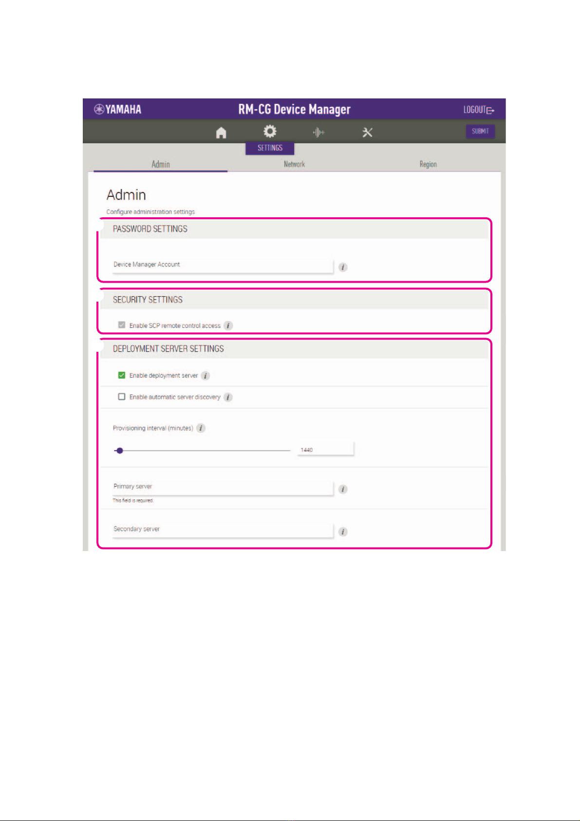
WEB GUI................................................................................................................................................................................4
Starting RM-CG Device Manager ............................................................................................................................................................ 4
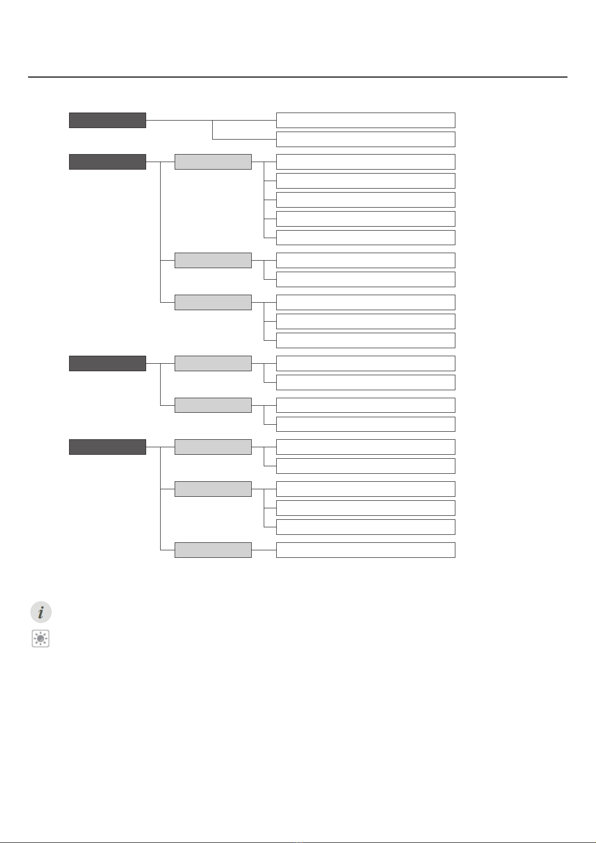
Structure of RM-CG Device Manager...................................................................................................................................................... 6
Functions of RM-CG Device Manager..................................................................................................................................................... 8
Alert log list ............................................................................................................................................................................................ 19
Thank you for purchasing the Yamaha RM-CG ceiling microphone. This document provides detailed information on the product functions
and specifications as well as the Web GUI. For correct and safe use of this product, be sure to first read this manual carefully together
with the RM-CG Installation Manual (included with the product).
Information
• The illustrations and images shown in this manual are for instructional purposes only.
• The company names and product names in this manual are trademarks or registered trademarks of their respective companies.
• We are continuously improving the software for our products. The latest version can be downloaded from the Yamaha website.
• This document is based on the latest specifications at the time of publication. The latest version can be downloaded from the Yamaha
website.
• Reproduction of this manual in whole or in part without permission is prohibited.
CONTENTS
INTRODUCTION
CEILING MICROPHONE
RM-CG
Reference Manual

RM-CG Reference Manual
2
Front panel
1Front panel indicator
NOTE: Occurrences of errors and severe errors are recorded in the alert log. For details, refer to page 19.
2Reset button
NOTE: Use a fine-tipped object such as an ejector pin to press the reset button.
CONTROLS AND FUNCTIONS
Condition Front panel indicator Unit status
LAN cable plugged into Dante/PoE port Lit green Microphone on
LAN cable plugged into Dante/PoE port Flashes green Starting up
Identify button in Web GUI clicked Flashes white Responding (to Identify function)
Updating firmware Flashes white quickly Firmware being updated
Updating firmware (After flashing white quickly)
Flashes green quickly Firmware updated successfully
Muted Lit red
(Flashes every 2 seconds) Microphone off
– Flashes red Error occurring
– Flashes red quickly Severe error occurring
Condition Front panel indicator Unit status
Reset button long-pressed for 4 seconds to less
than 8 seconds, then released
Flashes blue twice per second
(during long-pressing/resetting)
Network-related settings
Waiting for resetting/Resetting
Reset button long-pressed for 8 seconds to less
than 12 seconds, then released
Flashes blue three times per second
(during long-pressing/resetting)
All settings
Waiting for resetting/Resetting
1 2
With grille Without grille

RM-CG Reference Manual
3
Side panel
1Network port indicators (Dante/PoE port)
NOTICE: • When disconnecting the LAN cable from the Dante/PoE port, wait at least five seconds before reconnecting the cable.
Otherwise, damage or malfunctions may result.
• With a Dante network, do not use the EEE function* of the network switch. Although mutual power consumption settings
are automatically adjusted between switches that support the EEE function, some switches do not perform that properly.
As a result, the switch’s EEE function may be enabled inappropriately in the Dante network, possibly degrading clock
synchronization performance and interrupting audio. Therefore, please note the following.
- When using managed switches, turn off the EEE function on all ports used for Dante. Do not use a switch that does not
allow the EEE function to be turned off.
- When using unmanaged switches, do not use switches that support the EEE function. In such switches, the EEE func-
tion cannot be turned off.
* EEE (Energy-Efficient Ethernet) function: Technology that reduces the power consumption of Ethernet devices during
periods of low network traffic; also known as Green Ethernet or IEEE802.3az.
Network port indicator Unit status
Left indicator lit green Link up
Left indicator flashes green Transferring data
Left indicator unlit Link down
Right indicator lit green Operating on word clock of peripheral device (master)
Right indicator flashes green Acting as word-clock master
Right indicator flashes orange Word clock unlocked
1

RM-CG Reference Manual
4
Use the Web GUI “RM-CG Device Manager” to check/change the settings of this unit.
IMPORTANT: Check/change the settings after the installation of this unit is completed. For details on installing this unit, refer to the
RM-CG Installation Manual.
Starting RM-CG Device Manager
Prepare the following.
• Computer
• LAN cable
1. Connect the computer to the network switch (where this unit is connected) with a LAN cable.
2. Download the application “RM Device Finder” from the Yamaha website (U.S.A. and Canada: https://
uc.yamaha.com/support/, Other countries: https://download.yamaha.com/), and then start it.
3. Select a network in the [Select Network Interface Card] window, and then click [OK].
4. Select this unit in the [Detected Devices] window, and then click [Browse].
The first login window of RM-CG Device Manager appears.
WEB GUI

RM-CG Reference Manual
5
5. Click the [SIGN UP] button in the first login window.
6. Specify a password in the password settings window, and then click the [SUBMIT] button.
7. Type the password into the login window, and then click the [LOGIN] button.
The [HOME] window appears.
This completes the startup.

RM-CG Reference Manual
6
Structure of RM-CG Device Manager
Refer to the page listed to the right for details on each item available in the various windows.
The following icons/buttons are used in RM-CG Device Manager.
(Information icon): Move the pointer over this icon to see more information about the item.
(Identify button): Click to cause the indicator of the corresponding device to flash.
[HOME] [SYSTEM STATUS]
[LED INDICATION STATUS]
[SETTINGS] [PASSWORD SETTINGS]
[SECURITY SETTINGS]
[DEPLOYMENT SERVER SETTINGS]
[SYSLOG SERVER SETTINGS]
[LED INDICATION SETTINGS]
[Admin]
[Network] [IP ADDRESS SETTINGS]
[HOST NAME SETTINGS]
[Region]
[TIME SETTINGS]
[DAYLIGHT SAVING SETTINGS]
[SYSTEM SETTINGS]
[MICROPHONE SETTINGS]
[DIGITAL SIGNAL PROCESSING SETTINGS]
[Processing]
[TOOLS] [Update]
[Dante] [INPUT STATUS]
[OUTPUT STATUS]
[DEVICE STATUS]
[FIRMWARE UPDATE]
[AUDIO]
[Configuration] [EXPORT CONFIGURATION]
[Logs]
[RESET DEFAULTS]
[DOWNLOAD LOGS]
[IMPORT CONFIGURATION]
Page 8
Page 8
Page 9
Page 9
Page 9
Page 10
Page 10
Page 11
Page 11
Page 12
Page 12
Page 12
Page 13
Page 14
Page 15
Page 15
Page 16
Page 16
Page 17
Page 17
Page 18
Page 17

RM-CG Reference Manual
7
IMPORTANT: Be sure to click the [SUBMIT] button after changing settings in RM-CG Device Manager. The [SUBMIT] button always
appears in the upper-right corner of the window.

RM-CG Reference Manual
8
Functions of RM-CG Device Manager
[HOME]
1[SYSTEM STATUS]
Allows you to check basic information on this unit.
2[LED INDICATION STATUS]
Allows you to check the status of the front panel indicator.
1
2

RM-CG Reference Manual
9
[SETTINGS]
[Admin]
1[PASSWORD SETTINGS]
Allows you to check/change the password for logging in to RM-CG Device Manager.
2[SECURITY SETTINGS]
3[DEPLOYMENT SERVER SETTINGS]
• Allows you to select whether to use a deployment server. If using a server, select whether to detect it automatically or configure it
manually.
• Allows you to check/adjust the server provisioning interval.
1
2
3

RM-CG Reference Manual
10
4[SYSLOG SERVER SETTINGS]
Allows you to select whether to use a syslog server.
5[LED INDICATION SETTINGS]
Allows you to check/adjust the brightness of the front panel indicator.
4
5

RM-CG Reference Manual
11
[Network]
1[IP ADDRESS SETTINGS]
Allows you to select whether to use DHCP.
2[HOST NAME SETTINGS]
Allows you to select whether to specify the host name of this unit automatically or manually.
1
2

RM-CG Reference Manual
12
[Region]
1[SYSTEM SETTINGS]
Allows you to specify the time zone.
2[TIME SETTINGS]
Allows you to select whether to use NTP.
3[DAYLIGHT SAVING SETTINGS]
Allows you to select whether to use daylight saving time with this unit.
1
2
3

RM-CG Reference Manual
13
[AUDIO]
[Processing]
1[MICROPHONE SETTINGS]
Allows you to check/adjust the tracking speed and area.
1

RM-CG Reference Manual
14
2[DIGITAL SIGNAL PROCESSING SETTINGS]
• Allows you to check/change settings for the following.
- Input gain
- Adaptive echo canceller
- Noise reduction
- Dereverberation
- Auto mixing
- Auto gain control (type and speed)
• Click a button in the [Audio processing diagram] to open a window for checking/changing parameters for digital signal processing.
IMPORTANT: Parameter changes are immediately reflected in the acoustics of the unit.
2

RM-CG Reference Manual
15
[Dante]
1[INPUT STATUS]
Allows you to check the Dante input status for each connected device.
2[OUTPUT STATUS]
Allows you to check the Dante output status for each connected device.
1
2

RM-CG Reference Manual
16
[TOOLS]
[Update]
1[DEVICE STATUS]
Allows you to check the versions of the firmware and Dante of this unit. The firmware and Dante of this unit can be updated when
[Ready] appears below [Updatability].
IMPORTANT: In order to update Dante, the network portion of this unit’s IP address and the network portion of Dante’s IP address
must be the same.
2[FIRMWARE UPDATE]
Allows you to update the firmware and Dante collectively or individually by dragging and dropping the update file(s) into the box, then
clicking the [EXECUTE] button.
1
2

RM-CG Reference Manual
17
[Configuration]
1[EXPORT CONFIGURATION]
Allows you to export the settings of this unit by clicking the [EXPORT] button.
2[IMPORT CONFIGURATION]
Allows you to import settings into this unit by dragging and dropping the settings file into the box, then clicking the [IMPORT] button.
NOTE: Create the settings file to be imported by editing the one exported in 1.
3[RESET DEFAULTS]
Allows you to reset the settings of this unit by clicking the [RESET] button.
IMPORTANT: Be sure to check what is to be reset before doing it.
1
2
3

RM-CG Reference Manual
18
[Logs]
1[DOWNLOAD LOGS]
Allows you to download logs by clicking the [DOWNLOAD] button.
NOTE: Be sure to read alert log list on the following pages for explanations on the displayed alert log and the recommended
solutions.
1

RM-CG Reference Manual
19
Alert log list
Display Description What to do
important mic CH* broken Important mic CH* broken. Please contact your Yamaha dealer.
Dante hardware error Dante has not started up correctly. Turn the power off, then turn the power on after
waiting at least six seconds. If this does not
solve the problem, please initialize the memory.
Should this also fails, contact your Yamaha
dealer.
Firmware update failed, because
of *
Failure of firmware update has occurred. Check firmware file on the firmware update
pages of Web GUI.
Firmware update failed, because
of internal error
Turn the power off, then turn the power on after
waiting at least six seconds. If this does not
solve the problem, please contact your Yamaha
dealer.
Web UI internal failure Internal failure has occurred in Web GUI. Turn the power off, then turn the power on after
waiting at least six seconds. If this does not
solve the problem, please initialize settings.
Should this also fails, contact your Yamaha
dealer.
failed to start audio proc The device audio has not started up correctly. Turn the power off, then turn on after waiting at
least six seconds. If this does not solve the
problem, please initialize the memory. Should
this also fails, contact your Yamaha dealer.
System error The device has not started up correctly.
Power unstable The device is not supplying power normally. Connect to a PoE compatible switch. If this does
not solve the problem, please turn the power off,
then turn on after waiting at least six seconds.
Should this also fail, contact your Yamaha
dealer.
Syslog setting error Failed to update syslog transfer servers. Turn the power off, then turn the power on after
waiting at least six seconds. If this does not
solve the problem, please initialize settings.
logging error Failed to restart logging.
Automatic audio tuning failed,
because of internal error.
Automatic audio tuning has failed, because
internal error has occurred.
Turn the power off, then turn the power on after
waiting at least six seconds. Please try again. If
this does not solve the problem, contact your
Yamaha dealer.
Dante started in fail safe mode Dante has started in failsafe mode. Execute Failsafe Recovery using Audinate’s
firmware update tool.
Unable to configure Dante,
because the Dante device is
locked.
Dante is currently limited to control settings,
because the device is locked.
Unlock device lock using Dante Controller or
check Dante Domain Manager settings.
Resume data lost The settings saved in internal memory has been
lost.
Initialize the memory. If this dose not solve the
problem, contact your Yamaha dealer.
Saving setting data failed The device has not started up correctly. Turn the power off, then turn the power on after
waiting at least six seconds. If this does not
solve the problem, please initialize the memory.
Contact your Yamaha dealer if problem still
exists.
CPU temperature too high CPU temperature has been too high. Turn the power off, let the CPU cool down. Turn
the power on again. If the temperature is still too
high, check the installation environment and
whether dirt or a foreign object could have
clogged the cooling fan, and clean the fan if
necessary.

RM-CG Reference Manual
20
Too many devices on the network Too many devices are connected to the
network.
Reduce the number of devices connected to the
network.
Configuration import failed,
because of file download failure
(*)
Configuration import has failed, because of file
download failure.
Check network, server address settings,
existence of configuration file at server.
Configuration import failed,
because of file format error (*)
Configuration import has failed, because of file
format error.
Check contents and format of configuration file.
Configuration import transfer
failed, because of wrong filename
or peripheral disconnected (*)
Configuration import transfer has failed,
because of wrong filename or peripheral
disconnected.
Check file name and connection status of
peripheral device.
Configuration import failed,
because the system is busy (*)
Configuration import has failed, because of
system busy.
Check device status and try again. If it is still
not working, please update firmware or reset all
of the settings.
Configuration import failed,
because of internal error (*)
Configuration import has failed, because of
internal error.
Try again. If its not working again, please
update firmware or reset all of settings.
Schedule data lost The schedule data saved in internal memory
has been lost.
If this occurs often, contact your Yamaha
dealer.
Peripheral communication error A peripheral device within the system was not
found on the network.
Power-on all peripheral devices in the system,
and make sure that they are correctly
connected to the network.
Factory reset failed Factory reset has failed.
–
* reset failed Partial reset has failed.
Web UI login failure by * Web GUI login failure has occurred by (IP
address).
Check password.
Scheduling event failed, because
of *
Scheduling event has failed. Check the number of scheduled events.
Audio processing restarted Audio processing failure has occurred, then
restarted.
If this occurs often, contact your Yamaha
dealer.
Display Description What to do
Manual Development Group
© 2020 Yamaha Corporation
Published 05/2021
IP-B0
Table of contents
Other Yamaha Microphone manuals

Yamaha
Yamaha YVC-1000 User manual

Yamaha
Yamaha MZ103Be User manual

Yamaha
Yamaha Subkick SKRM100 User manual

Yamaha
Yamaha YVC-1000 User manual

Yamaha
Yamaha AG01 User manual

Yamaha
Yamaha RMWAP8 User manual

Yamaha
Yamaha XW-CS-700 User manual

Yamaha
Yamaha RM-TT User manual

Yamaha
Yamaha RM-TT User manual

Yamaha
Yamaha RMWMIC User manual
Popular Microphone manuals by other brands

AKG
AKG CBL 410 PCC User instructions

Sennheiser
Sennheiser MKE 416-48U3 instruction manual

Crown
Crown PZM-11LLWR datasheet

Cyber Acoustics
Cyber Acoustics CVL-2004 owner's guide

LY International Electronics
LY International Electronics CM12 Operation instructions

Audio Technica
Audio Technica UniPoint AT857AMLx Product information