Yamaha XW-CS-700 User manual

XW-CS-700
Wireless extension microphone kit
for the Yamaha CS-700
Congratulations on your purchase of the XW-CS-700, a wireless extension microphone kit for the Yamaha CS-700. The
XW-CS-700 allows additional microphone pick-up in a room without having to wire the room with audio cables, allowing
for a clean extension of the microphone capture of the Yamaha CS-700.
Please read the safety documentation for the components that are part of the XW-CS-700 kit carefully and follow their
instructions.
The components in this kit will require to be prepared before first use. Please follow the set-up instructions as provided
in this document.

1
2
3
Components
The XW-CS-700 kit includes the following components. Please check that you received all of them:
1 Revolabs™HD dual™:The HD dual includes the Receiver for the wireless microphone, the Charger to charge up
to two microphones, and the required power adapters.
1 Revolabs HD™omni-directional wireless microphone.
1 Proprietary audio cable to connect the HD dual Receiver to the CS-700.
1 User guide (this document).
Preparing the wireless Receiver
Before enabling the wireless extension microphone with the CS-700, the wireless Receiver needs to be configured and a
connection between the wireless extension microphone and the Receiver needs to be created.
Charging the microphones
First, please charge the microphone battery for at least an hour to ensure that enough charge is in the battery to go
through the process. To charge, connect the Charger to the main powers using one of the provided 5VDC AC Adapters
and using an appropriate power outlet 110-240 AC, 50-60Hz. The power LED on the Charger will illuminate. Place the
microphone in the Charger and ensure that it is seated well in the charging bay. Either a solid red LED (charging) or solid
green LED (100% charged) light will appear to confirm that the microphone is inserted properly. While in the Charger, the
microphones are not transmitting audio to the Receiver. In normal use, batteries should fully charge in about 2 hours, but
will “quick-charge” to 80% capacity in approximately 1 hour and 20 minutes. Fully charged microphones left in the Charger
remain solid green. Before first use of the microphone it should be charged for several hours or until the LED on the
microphone turns green in the Charger.
Whenever microphones are not in use, they should be inserted into the Charger. It is important to ensure that all
microphones are inserted fully so that charging will occur. Features of the Charger are shown in the following image.
1. LED indicator —power status indicator
2. Charger Bays —charges up to 2 Microphones
3. Power Cord Receptacle —power supply input, 5 VDC (on rear)
Important: The Serial Number of the Microphones used with the XW-CS-700 should start with a 7010 or 8020.
Serial numbers starting with numbers different than 7010 or 8020 are not approved to be used with the CS-700
extension microphone kit! In the supported microphones the Lithium Polymer rechargeable batteries that
power the microphones are field replaceable. Replace the batteries only with the manufacturer and model
battery type recommended by Yamaha Unified Communications. Please contact Yamaha Unified
Communications (uc.yamaha.com) for correct manufacturer approved and recommended replacement type
batteries.
Caution: Risk of explosion if batteries are mishandled or replaced by an incorrect type. Do not disassemble
batteries or attempt to charge outside the system. Do not dispose of batteries in fire. Dispose of batteries in
accordance with manufacturer’s instructions and local regulations.

Pairing the wireless microphone to the Receiver
Pairing creates a link between the wireless microphone and the Receiver, with a unique identifier. This process only needs
to be done once. Afterwards the microphone will automatically try to connect to the same Receiver whenever it is lifted
from the Charger or otherwise switched on.
Receiver front view
Rear View
(1) Channel LED indicators: Displays microphone status and pairing state, Channel 1 and 2
(2) Pairing Push Buttons: For pairing microphones to the Receiver, Channel 1 and 2
(3) Power-in Receptacle (5 V DC)
(4) 3.5mm Balanced Input Connectors
(5) 3.5mm Balanced Output Connectors
(6) Mini-USB Serial Interface for firmware upgrades and management
(7) Configuration DIP
To pair the microphone to the Receiver:
1. Turn the microphone OFF (no LED activity). If the microphone is ON, press and hold the Mute button for 10
seconds until the LED turns solid red then release the button to turn the unit off. (do not release the button when
you hear two beeps).
2. Place the microphone unit into pairing mode by holding the button down for seven seconds. The LED will first turn
green, then solid red. Release the button once the LED is red. The microphone is now in pairing mode.
3. Within one minute, push and hold the button for channel one on the Receiver for seven seconds until the LED
turns solid red, then release. The LED for that channel will be solid red until the microphone and the Receiver have
a wireless handshake to create the pairing, as indicated by a quick green flash. Please note that the pairing might
take a minute or longer to occur. Once the connection is established both the microphone and the Receiver LED
will turn to flashing red. To activate the microphone press the mute button once, the LEDs will switch colors to
blinking green.
1
2
3
4
5
6
7
Mute button

Setting the DIP-witches
Please ensure that the DIP switches on the back of the Receiver are set as bellow:
This setting ensures that the output of the Receiver provides mixed audio from microphone one and two in case more
than one microphone is being used (DIP 1), that no Low-pass filter is activated (DIP 2), that the Receiver provides mic-
level output (DIP 3), that the mute button on the microphone is not being used, audio will be sent in all cases (DIP 4), no
EQ will be applied (DIP 5 & 6), and the highest possible wireless signal strength shall be used (DIP7 & 8).
Advanced Configuration settings
Advanced Configuration settings can be made using the Revolabs™ HD Control Panel Software. They are not required
for a successful operation of the wireless microphone but might be useful in specific meeting room settings. For a full
description of that software visit the Revolabs™ HD Single/Dual user documentation.
To use the HD Control Panel Software:
1. Download the Revolabs HD Control Panel software from https://uc.yamaha.com/products/microphone-
systems/hd-wireless-microphone-system/
2. Connect the PC to the HD Single/Dual Receiver via USB.
3. Allow the PC to recognize the hardware and install the necessary operating system drivers.
4. Install the software downloaded in Step 1, which requires Windows 7 or newer.
5. Launch the Revolabs HD Control Panel program.
Configuration Settings
The Revolabs HD Control Panel controls most of the HD Single/Dual Receiver configuration settings. It also provides real
time status of the microphones. Only one HD Single/Dual system can be controlled and monitored from a single PC at any
given time.
Some settings you might consider:
(1) Enable Mics Unmute at Startup:
By default, the mics go into a muted state when they are removed from the Charger. This is done to prevent
handling noise as the microphone is placed into position. By selecting ‘Mics Unmuted at Startup’, the mics will go
into an unmuted state when removed from the Charger and become immediately active.
(2) Gain:
Each microphone has an individual gain fader. This fader provides +/- 10dB of gain in 0.5dB increments. The
microphone gains are stored in the Receiver and will be applied to any microphone paired to that channel. This
setting is useful to finetune the audio level of the wireless microphone.

Connecting the Wireless Receiver to the Yamaha CS-700
The proprietary audio cable included in the kit allows to connect the wireless Receiver to the CS-700 unit. Plug the
3.5mm side of the cable into the “Ch1 Out” receptacles. Ensure that DIP switch 1 was set to “On” ensuring that the
output carries both audio streams in case two microphones are being used.
Connect the other side of the audio cable to the extension microphone connector on the back of the CS-700.
Placement of the Wireless Microphone Receiver
As the microphone communicates wirelessly with the Receiver, some rules need to be applied when selecting the right
place for the Receiver in the room.
Best is an open “line of sight” placement with no obstruction between the microphone and the Receiver. In most cases
of installations this cannot be achieved, but trying to achieve an installation that comes as close as “line of sight” will
ensure best wireless reception.
Examples for places to be avoided for the Receiver during installation are behind metal objects, whether meshed or
solid. The Receiver should not be placed behind displays in the room as they cause wireless interference and are highly
absorbent of the radio signal.
An installation high in the room helps reception of the wireless signal. As people and objects they bring into the room
with them also absorb radio signals, a Receiver installed high in the room is less affected by these absorptions.
Placement of the Microphone Charger
The microphone Charger can be placed anywhere in the room. We recommend a location where it is easy to take the
microphone and replace it after a meeting for charging before the next meeting.

Using the Omni-Directional Tabletop Wireless Microphone
The Omni-directional Tabletop Wireless Boundary Microphone enables multiple conference attendees to use a single
microphone.
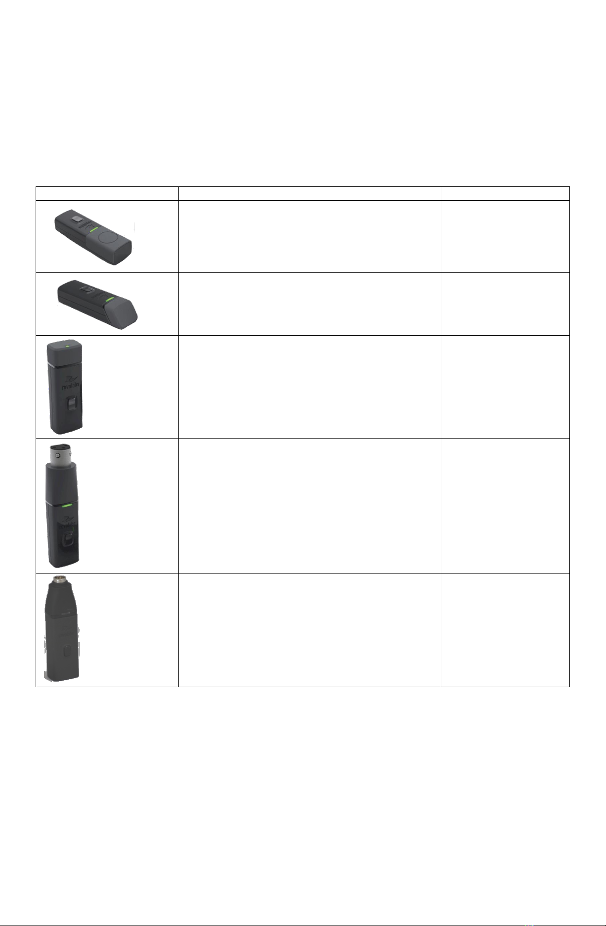
1. LED display —visual status for microphone status, like not-yet-activated, activated, and pairing.
2. Mute button —if DIP switches are configured as described above, this button will allow to activate the
microphone after it has been taken out of the Charger but has no effect thereafter. The button also allows to
switch the microphone on/off, or place it in pairing mode.
3. Audio jack —not used.
4. Charging port —connection to Revolabs HD Charger.
5. Rubber feet —non-slip, vibration absorbing pads.
6. Acoustic Cover —protects delicate microphone element (non-removable).
To use the HD Omni Tabletop Microphone:
1. Remove the microphone from the Charger. It will automatically turn on.
2. Once the microphone has connected to the Receiver, indicated by a flashing red LED, press the mute button to
activate the microphone. This is indicated by a flashing green light. Please note that based on the use of the
wireless frequencies it might take several seconds until the microphone and the Receiver link. During that time
the LED on the microphone will flash green, red, and yellow.
3. Once the LED is flashing green, the microphone is ready for use and is capturing audio.
4. Omni Tabletop microphones should be placed on the table, about 10 feet away from the CS-700 and within 2 to
6 feet (0.6 to 2m) from people speaking. The microphone does not need to be pointing in any particular
direction as sound pick up is from all directions. It is always better to place the microphone as close to the
person speaking as possible but avoid placing the microphone where it might be blocked by equipment or
paperwork. Make sure that the microphone is always placed lying on its rubber feet atop a flat surface.
5. To turn the microphone off, return the microphone to the Charger.
If the microphones are taken too far from the Receiver (based on the DIP switch settings up to ~150 feet or 50 meters)
the connection will be dropped (LED flashes all colors) and the microphone will mute. After 15 seconds the microphone
will beep 5 times and will continue beeping every 30 seconds to indicating that it is out of range.
Move the microphone closer to the Receiver and the connection will automatically be re-established to its original state,
and the beeping will cease. If not, the microphone will continue beeping until it turns off after about 15 minutes.
Microphone mute status and indicator
If the DIP switches were configured as described earlier in this document, the mute button on the microphone has no
effect after the initial start and once the LED has turned green. The microphone LED light will remain green indicating
that audio is being sent to the CS-700.
However, the mute control on the CS-700 main unit controls audio behavior for the complete system. When the mute
light is red on the CS-700 main unit, neither audio from the CS-700 microphone array nor the wireless extension
microphone is sent to the far end, even though the LED on the wireless extension microphone will remain green.
6
2
3
1
4
5
360 º pickup
pattern

Microphone Indicator lights
The LED indicator on the microphone and the Receiver can change based on the current state the microphone is in.
Please see the below table of possible LED indicators. Note that this table is based on the DIP-settings earlier discussed
in this document. If different DIP-settings are selected other behavior might be seen.
Equipment Use
Microphone LED
Receiver
Channel LEDs
Meaning
Microphone in Charger
Solid RED
OFF
Charging in Progress
Solid GREEN
OFF
Charging Complete
Microphone not in
Charger
OFF
OFF
Microphone powered OFF or
battery discharged
Two RED flashes
every 1.5 seconds
Two RED flashes
every 1.5 seconds
Microphone paired and not yet
activated. Press the mute
button to activate the
microphone.
One GREEN flash
every 1.5 seconds
GREEN flash every
1.5 seconds
Microphone paired and “active”.
Solid RED
Solid RED
Pairing mode or confirmation of
powering-down.
Alternating slow
GREEN and RED
Alternating slow
GREEN and RED
Microphone not paired / No
microphone paired to channel
YELLOW flash
alternating with
GREEN flash
GREEN Flashing
Microphone low battery
warning, microphone is “active”
YELLOW flash
alternating with two
RED flashes
RED Flashing
Microphone low battery
warning, microphone not yet
activated (press the mute
button to activate)
Alternating RED,
YELLOW, GREEN
OFF
Establishing connection, or out
of radio range. The
Microphone will try to establish
the link for about 15 minutes,
and then turn off automatically.
Rapid RED flashes
continuing for more
than a few seconds
OFF
Radio congestion –it is not
possible to make a radio
connection because there are
already too many nearby users,
or there is heavy radio
interference. Possibilities
include some types of digital
wireless devices or other
Revolabs products in the
vicinity.
Groups of five rapid
RED flashes
OFF
Unit is faulty. Contact your AV
service provider for advice.
Adding a second wireless microphone
The Receiver of the XM-CS-700 wireless extension microphone can handle up to two wireless microphones. It is
therefore possible to add a second microphone to the solution. It is important that the DIP-switch settings are done as
described earlier in this document, allowing two microphone channels to be mixed within the Receiver and sent to the
CS-700.
As part of the Revolabs™ HD microphone series, Yamaha offers different microphone types which can be added to the
XM-CS-700.
Best results can be achieved using table-top microphones like the omni-directional and the directional HD tabletop
microphones. Using any microphone that typically changes location during the call, like a wearable, an XLR adapter
being used with a hand-held microphone, or a countryman-adapter used with a lapel microphone, might cause echo on
the far end of the call while the microphone moves in the room and shortly thereafter.
To use two microphones, DIP switch 1 has to be in the ON setting as indicated earlier. Otherwise the audio of the two
microphones is not being mixed.
To pair the second microphone to the Receiver:
1. Turn the microphone OFF (no LED activity). If the microphone is ON, press and hold the Mute button for 10
seconds until the LED turns solid red then release the button to turn the unit off. (do not release the button when
you hear two beeps).

2. Place the microphone unit into pairing mode by holding the button down for seven seconds. The LED will first turn
green, then solid red. Release the button once the LED is red. The microphone is now in pairing mode.
3. Within one minute, push and hold the button for channel two on the Receiver for seven seconds until the LED
turns solid red, then release. The LED for that channel will be solid red until the microphone and the Receiver have
a wireless handshake to create the pairing, as indicated by a quick green flash. Please note that the pairing might
take a minute or longer to occur. Once the connection is established both the microphone and the Receiver LED
will turn to flashing red. To activate the microphone press the mute button once, the LEDs will switch colors to
blinking green.
Available microphones that can be used with the wireless extension microphone for the CS-700:
Microphone
Description
Yamaha UC SKU
HD Omni-Directional Wireless Boundary Microphone
01-HDTBLMIC-OM-11
HD Directional Wireless Boundary Microphone
01-HDTBLMIC-DR-11
HD Wearable Wireless Microphone
01-HDEXEMIC-11
HD XLR Microphone Wireless Adapter
01-HDXLRMIC-11
HD Wireless Adapter for Countryman Microphone
01-HDCOMAN-11
Trouble shooting
The microphone does not want to go into pairing mode.
Before the microphone can be put into pairing mode, it needs to be shut off. Hold the button for several seconds, until
the LED turns constant red. Ignore a possible beep from the microphone while doing this. Once the LED is constant red,
release the button. The LED should now be off, the microphone is turned off. Now press the button again and keep it
pressed until the LED turns on and after a few seconds turns constant red. Release the button. The LED should remain
constant red. The microphone is now in pairing mode. Follow the descriptions in this manual to put the Receiver into
pairing mode as well to create the connection between the microphone and the Receiver.
When taking the microphone out of the Charger, the LED blinks red and no audio is flowing.
This is normal behavior unless the microphone was set to “unmute at start-up” in the Control panel. Press the mute
button and release it –the LED should now turn to a blinking green

Muting the wireless microphone has no impact on the CS-700 mute status.
Once the LED light of the microphone is blinking green, pressing the mute button should have no effect –the LED should
remain green. If the LED changes colors from green blinking to red blinking and back whenever the mute button is
pressed, the DIP switch setting on the Receiver is incorrect. Recheck and correct the DIP-switch settings and restart the
Receiver.
The CS-700 microphone mute light is red, but the wireless extension microphone’s LED is green.
That is correct behavior. The microphone LED does not reflect the mute status of the CS-700. The microphone LED
(once activated after it has been taken out of the charger) should always blink green. The mute LED on the CS-700
indicates whether audio is flowing to the far-end of the call.
The LED on the microphone is blinking green –red.
The microphone is not yet paired to the Receiver, or was unpaired from the receiver. Follow the pairing instructions in
this manual to pair the microphone and the Receiver.
I have two microphones paired to the Receiver, but only audio from one is transmitted.
The audio of the two microphones is not mixed in the Receiver. Ensure that the DIP switches are set as described earlier
in this document and restart the Receiver.
Frequently Asked Questions
Q: Can a wireless and a wired extension microphone for the CS-700 be used at the same time?
A: No. The wired and the wireless extension microphone for the CS-700 use the same connector on the back. Only one
of them at a time can be connected.

© Yamaha Corporation. All Rights Reserved.
Published 05/2019
SC-XWCS-201905-EN/ 2950305-00
V 1.0
Manufacturer: Yamaha Unified Communications, Inc.
Address: 144 North Road, Suite 3250
Sudbury, MA 01776, USA
Table of contents
Other Yamaha Microphone manuals

Yamaha
Yamaha YVC-MIC1000EX User manual

Yamaha
Yamaha RM-TT User manual

Yamaha
Yamaha DM-105 User manual

Yamaha
Yamaha RM-TT User manual

Yamaha
Yamaha YVC-1000 User manual

Yamaha
Yamaha PGM1 User manual

Yamaha
Yamaha RMWAP8 User manual

Yamaha
Yamaha Subkick SKRM100 User manual

Yamaha
Yamaha PJP-25URS User manual

Yamaha
Yamaha YVC-1000 User manual
Popular Microphone manuals by other brands

Sandberg
Sandberg 126-07 quick guide

Merlaud
Merlaud DARS16 Operation & maintenance instructions

PCB Piezotronics
PCB Piezotronics 377C01 Installation and operating manual

Que Audio
Que Audio QA22 quick start guide

Micro Innovations
Micro Innovations MM760M quick start guide

ADX
ADX FIRECAST C01 instruction manual