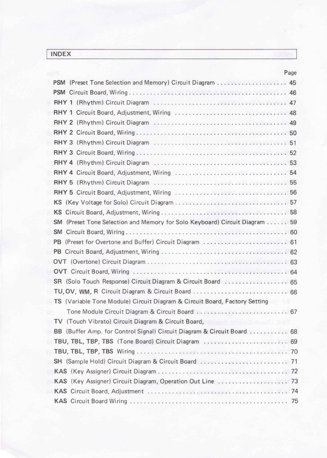
manuals.online logo
Brands
  1. Home
  2. •
  3. Brands
  4. •
  5. Yamaha
  6. •
  7. Synthesizer
  8. •
  9. Yamaha Electone GX-1 User manual

Yamaha Electone GX-1 User manual

0
AA
Neg
ate
WH
ode
i
rent
NR
=
——
=
=
i
eget
Soe
_
SERVICE
MANU
SS
=
—
ate
3
a
8
ees
ca
<
a
Sapo
=
.
a
—
re
terns
j =
=
:
ae
yee
ap
“3
SINCE
1887
5
@
NIPPON
GAKKI
CO.,LTD.
Hamamatsu,
Japan
—
{\
INTRODUCTION
|
This
manual
contains
service
information
for
the
Synthesizer
Electone
GX-1.
This
model
is
the
fully
using
sillicon
transistors
(NPN
and
PNP
type)
and
Integrated
Circuits
(and
or
LSI).
Take
special
care
to
the
following
points
before
making
any
service:
1)
Check
the
main
voltage
and
cycles
of
the
organ
and
ascertain
if
they
are
correctly
adjusted
to
the
electric
power
supply
in
the
area
where
the
organ
is
used.
\f
higher
voltage
is
applied
to
the
organ
by
mistake,
transis-
tors
and
or
ICs
will
be
inevitable
distroyed.
2)
Correct
voltage
and
polarity
should
be
observed
when
using
a
tester
(VOM)
in
order
to
avoid
damage
to
transistors,
ICs
and
FETs:
3)
Turn
the
organ
off
during
disassembly
and
parts
replacement.
Recheck
all
work
before
applying
power.
Transistors
and
ICs are
very
unforgiving
and
destruction
is
immediate.
4)
When
replacing
Integrated
Circuit
be
very careful
not
to
apply
excessive
heat,
proper
heat
sinking
devices
should
be
used.
5)
Before
replacing
an
Integrated
circuit,
always
disconnect
its
output
connections
and
recheck
for
a
signal.
|
INDEX
Page
GX-1.
SPECIFICATIONS
......
mexgerG
tipsike
Coioman
One,
001)
palace
ant,
faery.
Me
1
GX-1
CIRCUIT
DIAGRAM
&
CIRCUIT
BOARD
Contents:of-
Girculit-Board:.........0.
i.
.%sknn
«<>.
ARISE
AINA
ATEN
E
SFP
Ee
8
Unit
Layout
(1).
scscscc
cc
rec
catata
ns
tedeestetorene
RON
JNBOTSHIOE
SBR
US,
Fo
ee
16
MSIE
LeaY
OWE
(2).
coco
sets.
cence
ts
conc
to
sencsaeeiea
cesta
se
te
rece
te
tate
SOP
MES
odie
eet
MEENDIONS,
eT
OR
Ae
Block
Glagram
(Wpper).
...........
6c
eee
SI
SRR
BUR,
&
TT
18
Block
Diagrany
WOWwer):
«.-.-.....-.sne
tee.
SRR
TQ)
UNA
Se
19
Blocks
Dirdgrarrn
(POGal
5)
sisi.
si.
.cscscocasnsan
toasts
ness
cote
te
sete
te
+o
UL
IVE
IBD.
TA,
PT
20
Block
Tipe
(5010)
«.........-.-.-.
on
siedn
wees
JUS
WRG
SINUS
JOU
NAAL
BY
zt
Block
Diagran
(Rhythm)
«.:.......4.ccciux,
GPE
SRENIDA
nok,
iin,
AP
22
Block
Bragram
(Pres
Ampi):
..:.:.-.ncccdescctocn:.
PODIRBERS
SINS?
AOWENRDS.
&.
PN,
23
‘Terminal-Function
‘Table
(Micircuit).-.......
BAruy,
JPetiENOA
Dsl
Magi.
27
rh
24
WM
.(Master
Generator):
Circuit
Diagram:
«...7e
1670
Jes
(plas
101
snetlal
NGA.
&
25
M:-.Girctiit.Board.,.
Adjustment
-
...:...i.-.0ccccccc-a.
OU
Ae
IeaMRUIDA
Sen
RUM.
©.
26
MS
.Cucit@Boardtiuyil.(bisodye7
Give
aaF
iOneN
HRB
AGS
2¢
anol
ere).
Mi
27
M-CircuiG
Board.Witring
(1)
......:..ccsciniseieeein.-.-
ones
TON
BD
Ne
2.
8228
Mi’
-Circuit-Board:Wiring
(2)
......
RIBS
Poss
Pee
bre.
arotievO
707
feces
T)
29
M.-Circuit:Board:Wiriag
(3):
-..:
..xc¢accecess.<.
RI
ASP
REUIDA
.IBOR
HESS
30
M
-
Cireuit-
Board:
Wiring
(4)
3s
0
cack
Bice
es.
PORE
THT)
LORORIRYO,
Oe!
31
M-GircuieBoard.
Wiring
(5)
-
..
<cenaccke
teins
nce
re
ei.
BODEN,
DIRQ
MOMS.
EE
S2
BA
(Complementary
Buffer
Amplifier)
Circuit
Diagram
.............00000
eee
33
BA
-Gircuit-
Board:
Wiring
-.-
2
6.
PSPS
BU
TE
BSS
I
Oa,
34
KP
(Key
Voltage
forPedal}
Circuit’
Diagram
as
HF
(S209
ING)
SRBHIBN
35
KP
‘Gircuit-Board;
Adjustment,
WInh@
ation
©.
PEI
VES
YS
VOOR
Bae
TS
L.
36
TEK
(Touch
Control,
Expression
and
Knee
Lever)
Circuit
Diagram
.............
37
FEK
-
Circuit
Boar
“Adjistment
Wiring
22s
vy
ISS
ic
JOU
NOY
IGF
SOT
ISO
UAITS
S,
38
STR
(Solo
Key
Transformation
and
Reverb)
Circuit
Diagram..........
eee
ee
39
SER
Circuit:Board;
Adjustment,
-
Wiring’.
«0.6
BESS
ST
RS
OE.
40
SS
(Solo
Sub
Oscillator)
Circuit
Diagram
fetid
3
(GYR
Tibi
SOIT
Seer,
Fe
41
SS:
Gircutt
Board,
Adjustment,Wiring::
«><...
SWEIS
FSiy
|
aneieerk
Yeas
Oe,
42
MOS
(Modulation
and
Sub
Oscillator)
Circuit
Diagram
...........
00.00
eee
eee
43
MOS.
Ciresut
Board,
Adjustment,
Wiring:
«
«6%
-..«.
FORPTHRUBA,
BISOS
SHS
otk
44
|
INDEX
Page
PSM
(Preset
Tone
Selection
and
Memory)
Circuit
Diagram
..............00005-
45
PSM
Circuit
Board;
Wirlng....
2...
GAAOS
THIGAIA
4
BAR
DAM
TRIN
SF
46
RY
“©
(Rhyshi)
Circuit,
Diagram.
23
a...
«aces
ws
ce
IROL
TOU).
10.
at
47
RHY
1
Gircuit
Board,
Adjustment
WIFING,
......0....c00000scecuceun
21)
Teoved
Tit
48
RHY
2
(Rhythm);
Circute
Diagram
2-3...
ss
on
wea
ses
LU)
Fue
ve) See
49
RAY
2
Circuit
Board,
Witihd
3233
e
ss
ck
ent
c
cuss
GROUT
mews
Jan
50
RHY
3
(Rhythm)
Circuit
Diagram:
cc...
aes
Se
de
eee?
Set
51
RH
Y.
3
Circuit
Boards
Wein
se
6s.
oes
ics
ie
ek
hae
ob
OO)
Re
aoe
52
RAY
4
CR
Gira)
Crete
Dag
ha
5.
secs
ses
ce
jose
se
cecegessseseseseo
ee
SONGUY
REOSR
aie
53
RHY
4
Circurt
Board;
Adjustment,
Wiring,
.............0.0..0.5...
HIVE)
ORE
Maes
54
RAY
5
(RAY)
CiIGUit
Diagram,
5.5.
<......5e
cece
eceteeseoe
ss
TE
OAS)
MaDe
Seat
55
RHY
5
Circuit
Boara;
Adjustment,
Wiring
........
Jsiucnio
A
eiiet.
cocoa
iscians
56
KS
(Key.
Voltage
for
Solo).
Circuit.
Diagram...
.niciosiGi
tina
satszensd
acea).
i
57
KS
Circuit
Board,
Adjustment,
Wiring...................::...,[email protected].
Gastil.
58
SM
(Preset
Tone
Selection
and
Memory
for
Solo
Keyboard)
Circuit
Diagram
......
59
SIME
GIFU
ERO
ARC
UIP
sooo
oc
co
ceecccccesececescsesecessiesiceucketee
©
Ee
OG.
et
S
60
PB
(Preset
for
Overtone
and Buffer)
Circuit
Diagram
.........
0...
ee
eee
61
PB
Circuit
Board,
Adjustment,
Witing......,.............:.0....
463
aoe
Dee
ea.
f
62
OVT
-(Overtone)
Circuit
Diagram:
.:.,
<0...
.....06..,..6.0.0:0:0,01
00
OB
BEY
OSD
eens
63
ONT
.
Circuit
Board
WG
oa
ich
ooh
ce.
orecelacecescjee
DY
De SO
a.
64
SR
(Solo
Touch
Response)
Circuit
Diagram
&
Circuit
Board
................4.
65
TU,OV,
WM,.R:
Circutt
Diagram
&
Circuit
Board
.............
auai@
hash.
ond).
&
66
TS
(Variable
Tone
Module)
Circuit
Diagram
&
Circuit
Board,
Factory
Setting
Tone
Module
Circuit
Diagram
&
Circuit
Beardik.
-rracntowee
.esed.
<ieit).
Fe
67
TV
(Touch
Vibrato)
Circuit
Diagram
&
Circuit
Board,
BB
(Buffer
Amp.
for
Control
Signal)
Circuit
Diagram
&
Circuit
Board
...........
68
TSU, TEL,-TBP,
TBS
(Tone
Send)
Gicult
Disgram
apiesieieccs® och
aid).
AIO69
THU,
TOL,
TOP,
TOS
Wing
—.-..
-.
|.
ai
ares
bcos
270
SH
(Sample
Hold)
Circuit
Diagram
&
Circuit
Board
...........
0...
eee
eee
eee
71
KAS
(Key
Assigner)
Circuit
Diagram
.
.....
...
onia¥t
saad
SOs
ag
teas
S
72
KAS
(Key
Assigner)
Circuit
Diagram,
Operation
Out
Line
................005.
Ts
KAS
Circuit
Board;
Adjustment
2.
..2......
anisiW
snes’
.
beaak
coves)
28
74
WAS
Gitcire
Board
Wing:
cee
a
es
es
ee
To
|
INDEX
|
:
Page
Keyboard
Gireihit
Diagram
(1).
............annws..
BIRO.
Lust),
Aatwe
eels
feitic
76
Keyboard
Circurt
Dragranu(2)QHS
THRAMTeULOA
bes
BOM
OANA
SAR
AMAR
LS.
77
PNol
(antec
trGilcult:Diagrann
(type
ness.
oe
ee
ones
co
oe
es
Owes
78
RN.
FC
7)
Ciecuit
Diagram:
(2)
oc
cccccs
ce
cc
ecveseain
FP]d
SUS
79
PN:
to
(Panet
eh)
Circuit
Diagrant
(3)
ss
or.
6S
Ow
ates
ene
80
PINo2
tamer)
CHCUIUDIGgrant
We
ee.
ck eS
LO
ee
on
ee
ee
81
PINS
Sfearteine
ONCE
OV
AGhAITY
(2)
cise
os
cisco
ake
Sos
a
baie
0c eo
ee
eda
renee
82
PN
2
(Panter
neieane
Diagrain
(3)
0
esse
es
ene
So
oieee
ele
ee
oe
ety
oe
eee
83
PINES:
(idle
MCUINC
DIGQNAINY
¢
cccte
retry
so
ssi
ns
oe
estan
bos
ves
ols
ces
ae
84
PNG
cane
reGirCUlC
DIdGIaIN
6
5
erten
ok
Gers
ss
Buea
es
Ses
ewes
85
PNESetanien
sy)
GINCUIG
DNagraIn
(0)
on
cee
es
oe
ss
be
sas
wise
eels
oct
ees
86
Plo
aner
oy
Circuit
Diagram
(2)
ca.
ees
Fea
ow
6s
iv
oe
vv
oe
oo
87
PIiiGarearel!
6)
CiHouit
Didgrany
(1)
cc.
re
iee
S
ee
sv
dw
Pier
es
88
PNig
ei
eanel'6)
Circuit
DiagramAZ))
ace
ee
sn
ee sk
EN
tree
re
ee
89
Piveomranelo)
Circuit
Didgranl
(a),
ceccecs
i.
6
oie
sive
cies
cin
so
o
ce
neers
ere
eas
90
Elo
ctrancio) Gircuit
Diagranl
(4)5=
2a
6c
ee
oa
ete
0
ee
91
PING
7
(rave
7)
CHTOUEE
DIAGN
aI
IN
coors
race
iis.
Soc
vse
Wit
oe
a
sue
9
otsasecaes
92
PN:S>
(Panels)
Circuit
Diagram
(1)
sree
orcs
seine
as
Oe
eee
93
RINGS
=
(Paniel’G)
Ginette
©)
gud
(yy
te
ccc
ks
see
ce
sds
se
ee
ee
ees
94
PIneo-teanel
9)
Gircurt
Diagrane
2
eran
ss
cs
Ss
ao
vis
eve
seeds
vi
ens
ooo
95
Knee
(Knee
Lever)
and
Exp.
(Expression)
Circuit
Diagram
...............005-
96
FG
(Tone Cabinet
Gonnector}
Circuit
Diagram...
0.65.
is
eee
vb
sa
enna
eee
97
Ponewoenn
wont
Circuit
Diagrani
(1)
<a...
6
oc
res
ee
oe
bee
ect
wees
ees
98
Sr
eg
99
PU
(Power
Supply
Unit)
Circuit
Board,
Adjustment
..
2...
cnc
ie
ve
eee
100
Power
Supply
Unit
Wiring
(1)
[General
Spec.]
........
0...
cece
eee
eee
eee
101
Power
Supply
Unit
Wiring
(2)
[UL
and
CSA
Spec.]
...............05.
eet
102
Power
Supply
Unit
Wiring
(3)
[North
European
Spec.]
..............4..
Fae
tea
103
Power
Supply
Unit
Wiring
(4)
[European
and
South
African
Spec.]
............
104
Power
Supply
Unit
Wiring
(5)
[Australian
Spec.)
.......
0...
cece
eee
eee
105
Power
Supply
Unit
Wiring
(6)
[Japanese
Spec.]
.......
0.0...
cece
eee
eee
ee
106
MB
1
(Mother
Board)
Circuit
Diagram...
Located
below
the
rack
............
107
MB
2
(Mother
Board)
Circuit
Diagram...
Located
below
the
rack
............
108
INDEX
t |
Page
initial
Glear.
Switch,
CircuttiDiagram.
2...
0.0...
nana
Abd
EE
FRG
beady
109
GX-1
GENERAL
INSPECTION
and
ADJUSTMENT
PROCEDURES
...........
110
GMT
PART
CISL
wns
esr
rccnctepns
errs
sso»
dey
Mapai
Meio
tt
jane.
f:
111
NOTE:
ABBREVIATIONS
OF
WIRE
COLOR
IN
ELECTONE
BE
BLACK
BRiiiacac
BAOQWN
—
RE
=.)
S500.
RED
OR
Geer
ORANGE
YG
Soe
VEUCEOW
GR
=k
GREEN
Erte
BLUE
NES
cocker
VIOLET
GY
ee
GRAY
WE
tc
cts
WHITE
GG
Aces
GRASS
GREEN
SB
ee
SKY
BLUE
PRs
PINK
TRS
eecreer
ces
TRANSPARENT
Ge
eee
TIN
PLATED
WIRE
Divisions
Master
Oscillator
Tone
Selectors
GX-1
(S/#
503
GX-1
SPECIFICATIONS
Upper
Manual:
Lower
Manual:
Pedals:
Solo
Manual:
Portament
Manual:
Upper
Manual:
Lower
Manual:
Pedals:
Solo
Manual:
Upper
Manual:
Lower
Manual:
Pedal:
Solo
Manual:
Preset
Tone
Module
Numbers
Upper
Manual:
Lower
Manual:
Pedal:
Solo
Manual:
Control
Levers
and
Lever
Switches
Pitch
Bend:
Coupler:
Sustain:
61
Keys
Cw~ca4
61-Keys
C~
Cy
25
Keys
Ci~c
37
Keys
C1~
Ca
Ci~
C4
2
successions
with
8
notes
—do.—
2
successions
with
one
note
(In
this
case,
two
oscillators
are
used
for
the
second
succession.)
One
succession
with
one
note
(Common-Portamento
Key)
10
10
10
10
20
(Each
module
freely
adjustable
for
any
tone.)
20
(
—do.—
)
20
(
—do.—
)
10
(
—do.—
)
Upper
Lower
Pedal
L
to
U
U
tok
Eto
P
S
to
U
Upper
Lower
Pedal
GX-1
(S/#
5030
~
)
Over
Tone:
UpperI—
1,2,
4,
5,6,
8.
Il-
1,2,3,4,
7,8.
LowerI—
1,2,4,5,6,8.
IL
+.
t,
2,
3,4,
7,8.
Pedal
I—
1/2,
1,
2,
5/2,
3, 4.
I-—
1/2,
1,
3/2,
2,
7/2,
4.
Solo
—
_
1/8,
1/2,
1,
2,
4,
8.
Volume:
Upper
Lower
Pedal
Brilliance:
Upper
Lower
Pedal
Resonance:
Upper
Lower
Pedal
Mixing:
Upper
Lower
Pedal
Reverb:
Upper
and
Lower
Solo
Total
Volume
Manual
Balance
GX-1
(S/#
503
Solo
section
Solo
Control
Levers
and
Levers
Switches
Sample/Hold:
Rhythm
Pattern
Selector
Switch
(SPREB,
MA,
HH,
CY1,
CY2,
BD,
LC,
HG,
BO)
VCF
VCO
Sample/Hold
Switch
Sample
Indicator
Lamp
Ring
Modulator:
Oscillator
Level
Oscillator
Speed
Solo
Keyboard
Noise
Level
Noise
Color
Normal
and
Modurated
Signal
Mixing
Lever
Envelope:
Attack
Time
Sustain
Pitch
Envelope:
Initial
Pitch
First
Decay
Second
Decay
Final
Pitch
Sub
Oscillator:
Function
.
Speed
VCA
VGF
VCO
Solo
Portament
Knee
Lever
Control:
Solo
Keyboard
Portament
Switch
GX-1
(S/#
5030~
)
Solo
Touch
Response:
Upper
Sub
Controler
Upper
Touch
Responce:
Random
Signal:
(noise)
Sub
Oscillator:
Knee
Control
Switch:
First
Touch
Attack
Time
Initial
Pitch
Second
Touch
Pitch
Brilliance
Volume
Sub
Oscillator
Speed
VCO
VCF
VCA
Third
Touch
Vibrato
Wah Wah
Resonance
Third
Touch
Vibrato
Wah
Wah
Resonance
VCF
VCO
Color
Function
Speed
VCA
VGF
VCO
Solo
Keyboard
Switch
Upper
Portament
Upper
Sustain
Sub
Oscillator
VCO
VCF
VCA
Speed
Upper
Portament
Lower
Sub
Controler
Sub
Oscillator:
Knee
Control
Switch:
Foot
Switch
Control
Selector
Others
Solo
Keyboard
Function
Speed
VCA
VCF
VCO
Lower
Sustain
Sub
Oscillator
VCO
VGE
VCA
Speed
Upper
Sub
Oscillator
Cancel
Lower
Sub
Oscillator
Cancel
Rhythm
Stop
Solo
Portament
Upper
Portament
Tuning:
Wave
Motion:
Over
Tone
Preset
Button:
Upper
Lower
Pedal
Solo
Upper
Lower
Pedal
II
Pedal
II’
1,
2,3,4,C
GX-1
(S/
#
503
GX-1
(S/#
5030~
)
Over
Tone
Preset
Selector
Switch:
1
Upper
If
II
Lower
I
II
Pedal
I
II
2
Upper
I
II
Lower
I
II
Pedal
_
I
II
3..eUpper
I
II
Lower
I
II
Pedal
I
II
Expression
Dynamic
Compressor:
Upper
Lower
Pedal
Solo
Rhythm
Expression
Pedal
Expression
Switch
Knee
Lever
Auto
Rhythm
14
Rhythm
3
Variations
Rhythm
Selector:
March
I,
March
II,
Swing,
Waltz,
Slow
Rock,
Jazz
Rock
I,
Jazz
Rock
II,
Tango,
Beguine,
Rumba,
Mambo,
Bossa
Nova,
Samba
I,
Samba
II.
Variation:
A,
B.
Imarge
Controler
Tempo
Swinger
Volume
Balance
GX-1
(S/#
503¢
Start
Synchro
Start
Tempo
Lamp
Power
Consumption
420W
100V
125V
110V
220V
117V
=
240V
Dimensions
GX-1
Width:
1,600
mm
Height:
1,135
mm
Depth:
800
mm
Weight:
300
kg
Bench:
Width:
1,455
mm
Height:
666
mm
Depth:
660
mm
Weight:
60
kg
Pedal
Keyboard:
Weight
27
kg
GX-1
(S/#
5031
GX-1
CIRCUIT
DIAGRAM
&
CIRCUIT
BOARD
GX-1
(S/#
5030
~
)
Contents
of
Circuit
Board
Circuit
Board
©
Contents
Location
MU,
ML
*
Voltage
Controled
Oscillator
(VCOIIL)
on
the
Rack
MP,
MS
*
Pitch
Control
Circuit
for
Voltage
Controled
Oscillator
*
Wave
Shaping
Converter
(W
S
C
Module)
*
Wave
Shaping
Converter
and
Doubler
(by
discrete
system)
*
Band
Pass
Filter
(Fixed)
*
High
Pass
Filter
(Fixed)
*
Sound
Source
Signal
(Wave
form)
Selector
Gate
Switching
Circuit
by
FET
Gate
*
Sound
Source
Signal
(Wave
form)
Selector
Voltage
Control
Amplifier
(Signal
level
can
be
chosen
continuously.)
*
Preamplifier
*
High
Pass
Filter
(Voltage
Controled
Filter)
*
Low
Pass
Filter
(Voltage
Controled
Filter)
*
Voltage
Controled
Amplifier
(Controled
by
Envelope
Generator)
*
Voltage
Controled
Amplifier
for
Level
Setting
*
Envelope
Generator
for
Voltage
Controled
Filter
*
Envelope
Generator
for
Voltage
Controled
Amplifier
GX-1
(S/#
5030
~
)
Contents
of
Circuit
Board
Circuit
Board
Contents
Location
KAS
(KAU
KAL)
*
Key
Corder
*
Key
Assigner
*
Clock
Oscillator
*
Octave
Ladder
Gate
*
Note
Ladder
Gate
*
8
Channel
Division
Gate
*
8
Channel
Timing
circuit
*
Voltage
¢
ollower
circuit
*
UK
Portament
circuit
*
QOut-Put
Voltage
Buffer
circuit
*
Initial
Clear
circuit
*
IC
Power
Supply
circuit
on
the
Keybed
K
P
*
Ladder
Network
for
Key
Voltage
*
Gate
Circuit
for
Gate
Circuit
*
Buffer
Amplifier
for
Key
Voltage
*
Gate
Keying
Circuit
for
MP
Circuit
Control
*
Key
Voltage
Follower
Circuit
on
the
Rack
aK
*
First
Touch
Detector
*
Second
Touch
Detector
*
Voltage
Controled
Amplifier
for
Solo
Signal
which
controled
by
Second
Touch
Detected
Signal.
*
Voltage
Controled
Amplifier
for
Solo
Sub
Oscillator
Control
which
controled
by
Second
Touch
Detected
Signal
*
Third
Touch
Detector
*
Knee
Lever
Detector
*.Voltage
Controled
Amplifier
for
UK
Sub
Oscillator
which
cont
oled
by
Knee
Lever
Detected
Signal
*
Voltage
Controled
Amplifier
for
LK Sub
Oscillator
on
the
Rack
Gx-1
(S/#
5030
~
|
Contents
of
Circuit
Board
Circuit
Board
Contents
Location
TEK
which
controled
by
Knee
Lever
Detected
Signal
*
Expression
Detector
*
Expression
Circuit
*
Dynamic
Range
Control
Circuit
*
Tone
Cabinet
Selector
and
Total
Volume
Control
Circuit
*
The
Amplifier
for
Output
on
the
Rack
STR
*
UK
Signal
Preamplifier
(2
Amplifiers)
-
ox
—do.—
*
SK
—do.—
"Pr.
—do.—
(one
amplifier)
*
UK
and
LK
Reverb
Signal
Pick
Up
Amplifier
“*
SK
Reverb
Signal
Driving
Amplifier
*
SK
Reverb
Signal
Pick
Up
Amplifier
*
SK
Key
Voltage
Converter
(Lenear Voltage
to
Logarithm
Voltage)
on
the
Rack
Ss
*
Random
Noise
Generator
(for
Ring
Modulator)
*
Portamento
Precedence
Circuit
(Portamento
Keyboard
Precede
to
Solo
Keyboard)
*
Portamento
Key
Voltage
Delay
Circuit
*
Solo
Sub
Oscillator
(VCOI)
*
Waveform
Converter
for
Solo
Sub
Oscillator
*
Oscillator
(VCOI)
for
Ring
Modulator
*
Ring
Modulator
on
the
Rack
GX-1
(S/#
5030~
)
Contents
of
Circuit
Board
Circuit
Board
Contents
Location
PSM
*
One
Preset
Tone
Selector
Button
Selection
and
Precedence
Circuit
(2
channels,
2
circuits)
*
10.6V
DC
Supply
Control
Circuit.......
20
*
Lamp
in
the
Preset
Tone
Selector
Button
Driving
Circuit
on
the
Rack
MOS
*
UK
and
LK
Reverb
Signal
Driving
Amplifier
*
Oscillator
for
Pulse
Width
Modulation
*
Pulse
Width
Modulation
Gate
*
Sub
Oscillator
for
UK
*
Waveform
Converter
for
UK
Sub
Oscillator
*
LK
Sub
Oscillator
*
Waveform
Converter
for
LK
Sub
Oscillator
*
Random
Noise
Generator
(for
UK)
on
the
Rack
RHY
1
*
Tempo
Clock
Oscillator
on
Auto
Rhythm
*
Comparator
for
Swinger
(7
circuits)
*
Basic
Voltage
Circuit
for
Swinger
*
Counter
for
Clock
Pulse
*
Counter
for
Waltz
and
5
measure
*
Up
Beat
Producing
Circuit
*
Down
and
Up
Beat
Control
Circuit
*
Rhythm
Stop
with
Foot
Switch
Operation
Circuit
on
the
Rack
GX-1
(S/
#
5030
~
Contents
of
Circuit
Board
Circuit
Board
Contents
Location
RHY
1
*
Synchro
Start
Operation
Circuit
on
the
Rack
*
Rhythm
Lamp
Driving
Circuit
*
Timing
Selection
Circuit
for
Lamp
Driving
Pulse
RHY
2
*
Up
Beat
Matrix
Circuit
on
the
Rack
*
Rhythm
Variation
Selector
Circuit
RHY
3
*
Down
Beat
Matrix
Circuit
on
the
Rack
*
Rhythm
Variation
Selector
Circuit
RHY
4
*
Rhythm
Sound
Source
Circuit,
Oscillator
System
on
the
Rack
Bass
Drum
(Long),
Bass
Drum
(Short),
Conga
(Low),
Conga
(High),
Bongo
(High),
Claves,
Cowbell,
Rim
Shot
*
Four
Pre-amplifiers
for
Auto
Rhythm
RHY
5
*
White
Noise
Generator
for
Rhythm
Sound
Source
on
the
Rack
and
UK,
LK,
PK
and
SK
Sound
Source
*
Oscillation
Noise
Generator
for
Rhythm
Sound
Source
*
White
Noise
Signal
Gate
for
Sound
Source
in
M
Circuit
*
Rhythm
Sound
Source,
Noise
System
Cymbal
1,
Cymbal
2,
High
Hat,
Snare
Drum
GX-1
(S/#
5030
~
)
Contents
of
Circuit
Board
Circuit
Board
Contents
Location
‘KS
*
Key
Voltage
Ladder
Network
*
Key
Voltage
Gate
Circuit
*
Key
Voltage
Buffer
Circuit
*
Tuning
Control
Circuit
for
Portamento
Keyboard
on the
Panel
2
SM
*
One
Preset
Tone
Selector
Button
Selection
and
Memory
Circuit
(One
channel
10
pcs.)
*
10.6V
DC
Supply
Control
Circuit
*
Lamp
in
the
Preset
Tone
Button
Driving
Circuit
on
the
Keybed
PB
*
UK
Sub
Oscillator
Signal
Buffer
Amplifier
for
VCO
in
M
Circuit
Board
*
UK
Sub
Oscillator
Signal
Buffer
Amplifier
for
VCF
in
M
Circuit
Board
*
UK
Sub
Oscillator
Signal
Buffer
Amplifier
for
VCA
in
M
Circuit
Board
*
LK
Sub
Oscillator
Signal
Buffer
Amplifier
for
VCO
in
M
Circuit
Board
*
LK
Sub
Oscillator
Signal
Buffer
Amplifier
for
VCF
in
M
Circuit
Board
*
LK
Sub
Oscillator
Signal
Buffer
Amplifier
for
VCA
in
M
Circuit
Board
*
UK
Sub
Oscillator
Cancel
Circuit
with
Foot
Switch
*
LK
Sub
Oscillator
Cancel
Circuit
with
Foot
Switch
*
Buffer
Amplifier
for
Panel
Effect
Levers
(15
circuits)
*
Single
Preset
Tone
Button
Selection
and
Memory
Circuit
for
Overtone
on
the
Keybed

Other manuals for Electone GX-1

3

Other Yamaha Synthesizer manuals

Yamaha SY55 User manual

Yamaha

Yamaha SY55 User manual

Yamaha CS-10 User manual

Yamaha

Yamaha CS-10 User manual

Yamaha DX9 User manual

Yamaha

Yamaha DX9 User manual

Yamaha S70 XS User manual

Yamaha

Yamaha S70 XS User manual

Yamaha PSR-S650 User manual

Yamaha

Yamaha PSR-S650 User manual

Yamaha CS-30 User manual

Yamaha

Yamaha CS-30 User manual

Yamaha YFP-70 User manual

Yamaha

Yamaha YFP-70 User manual

Yamaha TX-802 User manual

Yamaha

Yamaha TX-802 User manual

Yamaha DX7 II FD User manual

Yamaha

Yamaha DX7 II FD User manual

Yamaha ARIUS YDP-181 User manual

Yamaha

Yamaha ARIUS YDP-181 User manual

Yamaha CS-60 User manual

Yamaha

Yamaha CS-60 User manual

Yamaha CX5MII User manual

Yamaha

Yamaha CX5MII User manual

Yamaha Harmony Director HD-300 Operating manual

Yamaha

Yamaha Harmony Director HD-300 Operating manual

Yamaha DGX620 - Portable Keyboard - 88 Keys User manual

Yamaha

Yamaha DGX620 - Portable Keyboard - 88 Keys User manual

Yamaha DX9 User manual

Yamaha

Yamaha DX9 User manual

Yamaha CS-5 User manual

Yamaha

Yamaha CS-5 User manual

Yamaha Electone CHX-1 User manual

Yamaha

Yamaha Electone CHX-1 User manual

Yamaha CS2x Instruction Manual

Yamaha

Yamaha CS2x Instruction Manual

Yamaha MOTIF 6 Instruction Manual

Yamaha

Yamaha MOTIF 6 Instruction Manual

Yamaha CS-5 User manual

Yamaha

Yamaha CS-5 User manual

Yamaha CP11 User manual

Yamaha

Yamaha CP11 User manual

Yamaha MOTIF XF User manual

Yamaha

Yamaha MOTIF XF User manual

Yamaha PF-15 User manual

Yamaha

Yamaha PF-15 User manual

Yamaha DTX-Multi 12 Mounting instructions

Yamaha

Yamaha DTX-Multi 12 Mounting instructions

Popular Synthesizer manuals by other brands

reKon audio MKS-80 manual

reKon audio

reKon audio MKS-80 manual

Roland Edirol StudioCanvas SD-80 Service notes

Roland

Roland Edirol StudioCanvas SD-80 Service notes

future.retro FR-777 Operator's manual

future.retro

future.retro FR-777 Operator's manual

future.retro Trax! owner's manual

future.retro

future.retro Trax! owner's manual

Studio Logic sledge Operation manual

Studio Logic

Studio Logic sledge Operation manual

Korg prologue owner's manual

Korg

Korg prologue owner's manual

Casio CT-S1BK manual

Casio

Casio CT-S1BK manual

Novation X-Station user guide

Novation

Novation X-Station user guide

Kong minilogue Service manual

Kong

Kong minilogue Service manual

Racal Instruments 3152 user manual

Racal Instruments

Racal Instruments 3152 user manual

Korg EK-50 quick start guide

Korg

Korg EK-50 quick start guide

Make Noise soundhack ECHOPHON manual

Make Noise

Make Noise soundhack ECHOPHON manual

Waldorf rocket user manual

Waldorf

Waldorf rocket user manual

Clavia nord STAGE Service manual

Clavia

Clavia nord STAGE Service manual

Patching Panda PUNCH V3 user manual

Patching Panda

Patching Panda PUNCH V3 user manual

Roland JX-305 owner's manual

Roland

Roland JX-305 owner's manual

Korg EasyStart X50 Easy start

Korg

Korg EasyStart X50 Easy start

GEM PK5 Oriental owner's manual

GEM

GEM PK5 Oriental owner's manual

manuals.online logo
manuals.online logoBrands
  • About & Mission
  • Contact us
  • Privacy Policy
  • Terms and Conditions

Copyright 2025 Manuals.Online. All Rights Reserved.