Yanmar 2GM20(F)(V)(C) User manual

MARINE DIESEL ENGINE
MODELS:
2GM20(F)M(C)
,
3GM30(F)M(C)
EPA Certified Engine
It meets the low emission standards set by the EPA
OPERATION MANUAL
California
Proposition
65
Warning
Diesel engine exhaust and some
of
its constituents are recognized by
the State
of
California
to
cause
cancer, birth defects, and other
reproductive harm.
J

Contents
CONTENTS
INTRODUCTION ...............................................3
1 FOR YOUR SAFETY....................................4
1.1 Warning symbols................................
.4
1.2 Safety Precautions..............................4
1.3 Warning Labels ...................................
?
2 PRODUCT EXPLANATION..........................8
2.1
Use, Driving System etc......................8
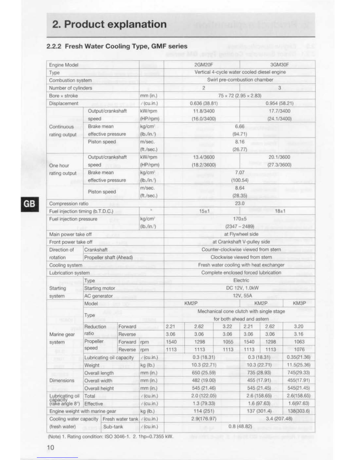
2.2 Engine
Specif
i
cations
..........................9
2.3 N
ames
of
Parts..................................
15
2.4
Major
Servicing Parts........................
16
2.5 Control Equipment............................17
2
.5.1
Control Panel .......
..
.................17
2.5.2 Single Lever Remote
Control Handle..............
..
........
19
2.5.3 Stopping Equipment...............19
2.5.4 Decompression Equipment...
..
19
3 OPERATION..............................................20
3.1
Fuel
Oi
l, Lube Oil & Cooling Water....20
3.1.1 Fuel O
il
...............................
..
...20
3.1.2 Lube Oil...................................21
3.1.3 Cooling Water.........................
21
3.2 Before Initial Operation .....................
22
3.2.1 Supply Fuel
011
........................
22
3.2.2 Supply Engine Lube
011
...........22
3.2.3
Supply
C
lu
tch
Lube Oil ...........23
3.2.4 Supply Cooling Water.............23
3.2.5 Cranking (Idling) ......................
24
3.2.6 Check and Resupply Lube
Oil and
Coo
li
ng Water.............25
3.3 Operating
your
Engine ......................25
3.3.1 I
nspec
ti
on Before Starting......
26
3.3.2
How
to Start
the
Engine..........27
3.3.3 Operation ................................29
2
3.3.4 Cautions during Operation......30
3.3.5
Stopping
th
e Engine ...............30
3.4 Long term Storage............................32
4 MAINTENANCE& INSP
ECnO
N ...............34
4.1
General Inspection
Ru
l
es
..................34
4.2
Li
st
of
Periodic Inspection
lt
ems
.......35
4.3 Periodic Inspection ltems..................37
4.3.1 Inspection
on
Initial 50 Hrs.
of
Ope
ration (or after1 month)....37
4.3.2 Inspection Every 50 H
ours
(or monthl
y)
.............................37
4.3.3 Inspection Every 150
Hr
s ........39
4.
3.4
Inspecti
on
Every 300 Hrs........39
4.3.5 Inspecti
on
Every 600 Hrs........40
4.4
EPA
Requirements...........................
.41
4.4.1 EPA Certifi
ca
tion Plate............
41
4.4.2 Conditions to Insure
Compliance with Emission
Standards................................42
4.4.3 Inspection and Maintenance ...44
4.4.4 Emission System Warranty
Statement................................
44
5 TROUBLE AND TROUBLESHOOTING .....45
6 PIPING DIAGRAMS...................................48
7 WIRING DIAGRAMS..................................50
APPENDIX A (Piping diagrams).....................A-1
(See the b
ack
of
this Manual)
APPENDIX B (Piping diagrams) ....................B
-1
(See the
back
of
this Manual)

Introduction
Thank you for purcha
si
ng a YANMAR
Mar
ine Diesel Engine.
This Operation Manual describes the operation. maintenance and inspection
of
the
2GM20(F)M(C), 3GM30(F)M(C) Yanmar Marine Diesel Engines.
Read
this
Operation Manual carefully before operating
the
engine
to
ensure
that
it
is used
correctly and
that
it
stays in the best possible condition.
Keep this Operation Manual in a convenient place
for
easy access.
If
this Operation Manual is
lost
or
damaged, order a new one from
your
dealer
or
distributor.
Make
sure
this
manual is transfered
to
subsequent owners. It should
be
considered as a
permanent part
of
the
engine and remain so.
Constant efforts are made
to
improve
the
quality and performance
of
Yanmar products,
so
some details included in this Operation Manual may differ slightly from your engine. If
you have any questions about this, please
contact
your Yanmar dealer
or
distributor.
The marine gear described in this manual is Yanmar Model KM Series.
Models 2GM20(F)M(C),
Operation Manual 3GM30(F)M(C)
(Marine Engine) Code. No. 499611 -00680
With regard
to
the
sail drive, this manual describes lube oil selection and specification
only. Please read the Sail Drive Operation Manual,
wh
ich is supplied with the Sail Drive
Unit,
for
furtherinformation.
-3

1. For your safety
1.1 WARNING
SYMB
OLS
Most
operation, maintenance and inspection problems arise due
to
users' failure
to
comply
with
the
rules and precaut1ons
for
safe operation described in this operation
manual. Often, users
do
not
understand
or
recognize the signs
of
approaching problems.
Improper handling can cause burns and other injuries and can result in death.
Be
sure
to
read this operation manual carefully before operating
the
engine and observe
all
of
the instructions and precautions described in this manual.
Below follow the warning signs used in this manual. Pay special attention
to
parts
containing these
words
and signs.
A DANGER DANGER indicates an imminently hazardous
situation which,
if
not
avoided, WILL result in death
or
serious injury.
A WARNING WARNING indicates a potentially hazardous situa-
tion which,
if
not
avoided, COULD result
in
death
or
serious injury.
A CAUTION CAUTION indicates a potentially hazardous situa-
tion which,
if
not
avoided,
may
result in
minor
or
moderate injury.
' This sign is also
be
used to alert against unsafe
practices.
The descriptions captioned
by
are particularly important cautions for
handling. If you ignore them, the performance
of
your
machine
may
deteriorate leading
to
problems.
1.2 SAFETY PRECAUTIONS
(Observe these instructions
for
your
own
safety!)
Pr
ec
aution
s
for
Op
erat
io
n
A DANGER
4
Filler
Cap
of
Fr
es
h
Wate
r
Tank
Neveropen
the
cap
of
the fresh water tank while
the
engine is still hot.
Steam and
hot
water
will spurt
out
and burn you seriously. Wait until
the temperature
of
the fresh
water
tank has
dropped
,
wrap
a cloth
around
the
filler
cap
and loosen
the
cap
slowly. After inspection,
refasten
the
cap
firmly.

1.
For
your
safety
A DANGER
A DANGER
A WARNING
A CAUTION
I
I
Ba
tt
ery
Never smoke
or
permit sparks near the battery, because
it
may emit
explosive hydrogen gas. Place the battery in a well-ventilated place.
Fuel
Use only diesel oil. Never use other fuel
s,
including gasoline, kerosene,
etc., because they could cause a fire. The wrong fuel could also cause
the fuel injection
pump
and injector
to
fail due to lack
of
proper
lubrication. Be sure to check that you have selected the correct diesel
fuel before filling the fuel tank.
Fire
Prevention
Be sure
to
stop the engine and confirm that there are no open flames
in the vicinity before supplying fuel. If you
do
spill fuel, wipe such
spillage carefully and dispose
of
the wiping materials properly. Wash
your
hands thorougly with soap and water.
Neverplace oil
or
otherflammable material in the engine room.
Install a fire extinguisher near the engine room, and familiarize yourself
with its use.
Exhaust
Gas
Exhaust gas contains poisonous carbon monoxide and should not be
inhaled.
Be sure
to
install ventilation ports
or
ventilators in the engine room and
ensure
good
ventilation during engine operation.
Moving
Part
s
Do
not
touch
or
let your clothing
get
caught in the moving parts
of
the
engine, such as the front drive shaft, V-belt
or
propeller shaft, during
engine operation. You will be injured.
Neveroperate t
he
engine without the covers on the moving parts.
Burns
The whole engine is hot during operation and immediately after
stopping. The exhaust manifold, exhaust pipe and high pressure fuel
pipe are very hot. Never touch these parts with your
body
or
clothing.
5

1. For your safety
A WARNING
A DANGER
A WARNING
A WARNING
-
•
•
_1
\..
7
~'t
A CAUTION
A DANGER
A DANGER
6
Al
co
hol
Never operate the engine while
you
are
under
the influence
of
alcohol.
Never operate
the
engine when
you
are ill
or
feeling unwell.
SAFETY
PRECAUTIONS
FOR INSPECTION
Batt
ery
Fluid
Battery fluid is dilute sulfuric acid. It can blind you
if it
gets
In
your
eyes,
or
burn
your
skin. Keep
the
fluid
away
fr
om
your
body. If you
touch It, wash
it
off
immediately with a large
quantity
or
fresh water
and call
your
doctor
for
treatment.
Fire
by
Electric
Short
-
Circuits
Always
turn
off
the battery switch before inspecting the electrical
system.
Failure
to
do
so
could
cause short-circuiting and fires.
Stop
the
engine
before
servicing
Stop
the
engine before you service it.
Turn
the
battery
switch
off.
If
you
must
inspect
while
the
engine
is
in
operation, never
touch
moving parts. Keep
your
body
and clothing well
clear
of
all moving parts.
Scalds
If
extracting oil
from
the
engine while
it
is still
hot
,
don't
let the oil
sp
lash
on
you.
Wait until the temperature has
dropped
before
extracting cooling
water
from
the engine. Don
't
let
it
splash on you.
Forbidden
Modifications
Never release
the
limiting devices
such
as
the engine speed limit, fuel
injection limit, etc.
Modification will
impair
the safety and performance
of
the
product
and
shorten
product
life.
Also
note
that
any troubles arising from modification are
not
covered
by
our
warranty.
Precautions
for
Treating
Waste
Never dispose
of
waste
oil
or
other
fluid in a field, sewer, river.
or
the
sea. Treat waste matters safely observing regulations
or
laws.
Ask
a waste recovery
company
to
col
l
ect
it.

1. Foryour safety
SAFETY PRECAUTIONS FOR INSPECTION
1.3 WARNING LABELS
To insure safe operation, warning device
labels have been attached. Their location is
shown below and they should always be
visible. Please replace
if
damaged
or
lost.
_r;;..!.;;.
~
Lr
...:::::::!
2GM20(C)M. 3GM30(C)M
2GM20F(C)M. 3GM30F(C)M
Warning Device Labels, Parts Numbers
~
~
No
.
CD
@
Part Code No.
---
128296-07350
128296-07260
l!!l E
•
~h
ell
• A
ot
a
tln
o
porto
.
• C• n ce u
ee
l"jury.
Ul2
tl
07)~0
e•
DANGER
••iiJW
t=
~:f,.
:;~
:TI!RI1
g:
~
n:"Fi!
~
'·
•llil
bl
~
~
tiJ
t..\'>l:t
~
~T~!!ln~IJ
.
ollovor
removo
tho
cep whllt
tho
ono
ino
11 1
1111
hot
. •
Hot
water
mor
1purt
out
e
nd
burn
you
.
7

2. Product explanation
2.1
USE, DRIVING
SYSTEM
,
ETC
.
The engine
is
equipped
with marine gear,
connect
the marine
gear
output
shaft
to
the
propeller shaft.
In
order
to
obtain
full
performance
from
your
engine,
it
is
imperative
that
you
check
the
size
and
structure
of
the
hull
and
use
a propeller
of
the
appropriate
size.
The engine
must
be
installed correctly with
safe
cooling
water
and
exhaust piping
and
electrical wiring. The PTO
work
should
be
easy
to
use
for
onboard
equipment.
To
handle the
drive
equipment
,
driven
systems
(including
the
propeller)
and
other
on
board
equipment,be
sure
to
observe
the
instructions
and
cautions given in
the
operation
manuals
supplied
by
the
shipyard
and
equipment
manufacturers.
The laws
of
some
countries
may
require hull and engine Inspections,
depending
on
the
use, size
and
cruising area
of
the
boat.
The installation, fitting
and
surveying
of
this engine all require specialized
know
ledge and
engineering skills.
Consult
Yanmar's local subsidiary in
your
region
or
your
distributor
or
dealer
.
A WARNING
Never
modify
this
product
or
release
the
limit
devices
(which limit engine
speed. fuel injection
quantity
, etc.).
Modification
will impair
the
safety
and
performance
of
the
product
and
functions
and
shorten
the
product
l
if
e.
Please
note
that
any
troubles
arising
from
modification
of
the
product
will
no
t
be
covered
by
our
warranty.
DETAIL
OF
NAME
PLATE
The name
plate
shown
below
is
attached
to
the
engine.
Check
the
engine's
model,
output,
rpm
and
serial
number
on
the
name plate.
MODEL
CONT.RAT
IN
G
kW
rpm
MAX
.OUT PUT
kW
rpm
ENGINE NO.
YliUfMA8
D~DHI.-E
8
The name plate
shown
below
is
described
in the marine gear.
Check
the
marine
gear's
model,
gear
ratio, oil used,
oil
quantity
and
serial
number.
v
MOD
EL
KM
__
,
GEAR
RATIO
OIL
SAE2
0IJo
HD
OIL
QTY.
LTR
.
NO
.
KIIIIZAICI
~
..) OSAKA
JAP
AN

•
2. Product explanation
2.2 Engine Specifications
2.2.1 Direct Seawater Cooling Type, GM series
IEngine Model
____
_
~
--
---
2GM20
Vert•cal4·cycle
-
+--------
I 3GM30
watercooled diesel engine
CombuStiOn system
------------4---------+----- combustion chamber
Swart
pre-
Number
of
cylinders
Bore x s
tr
oke
mm
(ln
.)
Displacement (!;u.m
.)
OutpuVcrankshaft kW/rpm
speed
IHP/mml
Continuous Brake mean
kg/em
rating output effectiVe pressure (lb./in.1
Piston speed m/sec.
(ft./sec.\
OutpuVcrankshaft kW/rpm
One
hour
speed
HP
/rR.m
rating output Brake mean
kg/em
effective pressure
~
lb./in.)
Piston speed
m/sec
.
(11./sec.)
Compression ratio
Fuel injecti
on
tim
1ng
(b.T.D.C.)
Fuel injection pressure kg/em
jlb.lin
)
Main
power
take
off
----
---
Front
power
take
off
-----
Direction
of
Crankshaft
rotation Propeller shaft (Ahead)
~--~---
Cooling
sys
tem
------
Lubrication system
~-'-'---
Startang
system
M
ar
ine
gear
sys
tem
Type
Starting
motor
ACgenerator
Model
Typ
e
Reduction
ratio Forward
Reverse
---.
----
--
Forward
rpm
~;_:_:=--j--
Propeller
speed Reverse
Lubricating
oaf
capacity
Weight
rpm
(cu.an.)
kg (lb.)
2
+--
----
-
75 X
3
72 (2.95 X 2.83)
0.636(38.81) I 0 954 (58.21)
11
.8/3400 I 17 7/3400
(16.0/3400) (24 1/3400)
6.66
(94.7
1)
8.16
(26.77)
13.
4/3600
20.1/3600
(
18
.2/3600) (27.313600)
7.07
(100.54)
8.
64
(28.35)
23.0
15±1
18
±1
-
170:5
(2347 - 2489)
at
Flywheel side
shaft V
-p
ulley side
kw
ise viewed from
stem
e viewed fr
om
stern
at
Crank
Counter-cloc
Cl
ockw
is
Dttectseawater
coo
ll
Complete enc
Elec
DC
ng
_(
rubber I
mpe
ll
er
wa
t
er
p
um
p)
Josed
forced lubncauon
tnc
and
manual
12V, 1.0kW
12V.
SSA
KM2P 1 KM3P
e cl
utch
with
single stage
ahead and astern
.22
2.21 2.62 I 3.20
.06 3.06 3.06 3.16
1540
1298
1063
113
I 1113
1113
1076
0.3 (18.31}
0.
35(21
.36)
10.3 (22.71)
11.5(25
.
361
Overa
lll
eng
lh
-----
mm
(in.)
mm
(ln.)
mm
Qn.)
735
(28.9)
740(29
13)
...;_
Dimensions Overall width 455 (17.91)
455(11.91)
Overall height 495 (
1950)
~95(19
5())
2.6 (158 65)
2.6(15865l
1.6(97.63)
161'3763)
129(283.8)
1301280)
9

2. Product explanation
2.2.2 Fresh Wat
er
Coo
l
ing
Type
, G
MF
series
Eng1ne
Model 2GM20F I 3GM30F -
Type
Vert1cal
4-cycle w
1------
______
Swirl pre-c
ater cooled diesel engine
ombustlon cham
be
r
Combustion system
Num
ber
of
cylinders
Bore • stroke
Displacement OutpuVcrankshaft
speed
Continuous Brakemean
rahng output effective pressure
Piston speed
OutpuVcrankshaft
One hour speed
rating out
put
Brake mean
effective pressure
L Piston speed
~
Compress1on ratio
liiil
FuellnJechon t
Fuel intecllon
pr
1mmg
(b.T.D.C.)
essure
eoff
Matn power tak
Front
power
ta
Direction of
rotallo_n
__
Cooling system
Lubrication sys
keoff
Crankshaft
Prope
ll
er
shaft (Ahead)
tem
Type
Start1ng
motor
AC generator
-'-
mm
(tn.)
(cu.in.)
kW
/rpm
(HP/rpm)
kg/em
(lbJin:')
m/sec.
(ft./sec.)
kW/rpm
(HP/rpm)
kg/em'
(lb./ln. )
m/sec.
j{ft.tsec.)
kg/em
_ QbJin.)
·-
-·
2 I
2 (2.95
)(
2.83)
75
)(
7
0.636 (38.81)
11.8/3400
(16.013400)
13.4/3600
(18.2/3600)
15:t1
2
(
at
6.66
(94.71)
8.16
(26.77)
7 07
(1
00.5
4)
8.64
(28.35)
23.0
170:t5
347 2489)
Flywheel side
3
0.954 (58.21)
17.7/3400
(2A
1/3400)
20.1/3600
(27.3/3600)
18±1
at CrankshaftV-pulley side
kwlse viewed from stern
Counter·cloc
s
Clockwt e viewed from stern
-
-
Fresh water c
Complete en
ooling with heat
e
:::.x..:
c_han=g~er:__
__
~--t
closed forced lubrication 1
Electric
__
___
_
DC
12V,l.OkW
--
----
12V.55A
:..:.._
____
~
__,
Starling
~tern
Model KM2P KM2P KM3P
Type
•
Reduction Forward
Marine
gear
ratio Reverse
f=------,,..----1
system Propeller Forward
speed
Mechanical
co
for
bot
ne
ha
2.21 2.62 3.22
~3
.
..:..06=--+~3.06
_+-....;
3.06
clutch
w1th
single
s1age
head and astern
2.21 2.62 3.20
3.06 3.06 3.16
1540 1298 1063
1113 1113 1076
0.3 (18.31) 0.35(21.36)
10.3 (22.71) 11.5(25.36)
735 (28.93) 745(29.
33)
455 (17.
91
) 455(17.91)
545
(21
.45)
545(21
.45)
--+-
2.6 {158.65) 2.6(158.65)
-
Lubricahng oil
~aoacttv
(ra
ke artgle 8•) 1.6(97.63) 1.6(97.63) -
Engine
we1ght
with
marineg
.,_e:..:car=---
--+
Cooling watercapacity Fresh water tank '(cu.ln
.)
+----
(fresh water) Sub-tank ' (cu.ln.)
(Note) 1 Rating condition: ISO 3046-1. 2. 1hp .0.7355 kW.
10
137 (301.4) 138(303.6)
3.4
(207.48)
0.8
(48.82)

2. Product explanation
2.2.3
Direct
Seawater
Coo
l
ing
T
ype
, G
MV
se
ries
nglne Model 2GM20
IE v
' -3GM30V
ype
Vert~eal4-
,_
T cycle watercooled diesel eng•'le
ombusllon system Swi ustlon chamberC
rt
pre-comb
Number
of
cylinders
B
orax stroke mm
(ln.)
Dlsplacement (cu.in.)
OutpuVcrankshaft kW/rpm
speed (HP/rpm)
Continuous Brake mean kg/em
2
75
X
72
(2
0.636 (38.
11.
(16.0134
81)
813400
00)
I 3
.
95
X 2.
83)
0.954 (58.21)
17.713400
(24
113400)
rating output
effectiv~e...!:p::.:re:.:s:::su::.r.:.e
__
-1-~
(lb::::./~ln.::..'l!-
_-+--------
.7
1)
6.66
(94
8.
(26
One hour
rabng output
Piston speed m/sec.
---1--....!:.(ft=-Jsee.)
OutpuVcrankshaft kW
/rpm
speed
(H
P/rpm)
Brake mean kg/em
effective pressure (lb./in.)
Piston speed mlsec.
(ft./sec.)
Compression
;_
r.::a
.::.
tio:__
__
_
Fuel Injection timing (b.T.DC.)
----+-
Fuel Injection pressure kg/em
Qb.lin.i
13.4/3600
_,_
_
_.!..(1:..::;8213600)
I
15±1
16
.77)
l
7.07
(100.54)
8.64
(28.35)
23.0
20.1/3600
(27.313600)
18
%1
----
170±5
(2347-
2489)
Matn power take off
------------·!------
at Flywheel side
Front power take off
at
Crankshaft V-puliey side
__
___:::_CI:.:.OC::;,kw
lse viewed from
Cranksh
.:.::
a
:;,:
fl
~---------+--
1Propellershafl (Ahead) stern
stern
Direction
of
rotation
Cool
tng
system Clockwise viewed from
ling (rubberim
nclosed forced
ectric andmanu
DC
12V, 1.0kW
Direct seawatercoo pellerwater pump)
Lubnc
· atloo system
•ng
m
Start
syste
e gear
m
Marin
syste
Dimensions
Lubr
iC~~bng
oil
Cl~
rrnre
a le
8j
IType
!Starting motor
AC generator
'Model
Type
Reduction Forward
ratio Reverse
Propeller Forward
speed Reverse
Lubrlcabng oil capacity
We1ght
Overall length
Overall width
Overall hetght
Total
JEttective
rpm
rpm
' (cu.ln.)
kg (lb.)
mm
Qn.)
mm(in.)
mm(in.)
' (cu.ln.)
(cu.in.) _
t-
Complete e
El
12V,55A
KM3V
V-drlve. mechanical cone clutch
ad and asternfor both ahe
2.61
316
1303
1076 i
0,8 (48.92)
19.5
(43.0)
486 (19.13)
455 (17.91)
495 (19.49)
2.0 (122.05)
1.3(79.33)
lubrication
al
with single stage
(Angle 15 )
320
3.16
1063
1076
591.5 (23.29)
455 (17.91)
495 (19.49)
2.6(158 65)
1.6
(97
.63)
·-
-
-
-
-
-
ne
weight with marine
gear
1 Engi kg (lb.) 119(261) 138
(303)
-L---
--~
(Note)
1.
Rating condition: ISO3046·1.
2.
lhp=0.7355 kW.
11

r
2. Product explanation
2.2.4 Fresh
Water
Cooling
Typ
e, GMFV
series
ne
Model
Eng!
Type
Com
Num
Bore
Disp
bustion system
ber of cylinders
x stroke
lacement Output/crankshaft
speed
JnUOUS
Brake
mean
Cont
rating output
effectiVe
pressure
1- Piston speed
Ou
tput/crankshaft
hour
One
rahng
output speed
Brake
mean
effective pressure
Piston speed
pressiOn
ratio
Com
Fuel
Fuel
tntection
tim1ng
(b.T.D.C.)
Injection pressure
power t
ake
oN
power
take
off
lion of
Main
Front
Dlrec
rotat
Cool
Lubnca
ion
ICrankshaft
Propellershaft
(Ahead)
lng
system
"
t10n
system
ing
Start
syste
m
egearM
arin
system
Type
Starting motor
AC
generator
Model
Type
Re
duction
ratio
1
Propeller
Ispeed
Forwa
rd
f-
R
everse
Forward
Reverse
Lubricating
011
capac•ty
WeJQhl
Overall length
D1me
nslons Overall width
Overall height
Cffling
oil Total
c~
a gle
8")
Effective
Lubrl
fr~~~
Eng
ineweight with marine gear
}
mm
On.)
(cu.in.)
kW/rpm
,(tiP/rpm)
kg/em
ObJin)
m/sec.
(fl./sec.)
kW/rpm
(HP/rpm)
kg/em
,
Ob./in.')
mlsec.
(ftJsec.)
-kg/em·
(lb./in.')
rpm
rpm
(cu.ln.)
~g
(lb.)
mm
Qn.)
mm
Qn.)
mm
(in.)
(cu
.in.)
·(cu.ln.)
kg
(l
b.)
(Note)
1 Rating condition:
ISO
3046·1
2.
1
hp=O.
7355
kW
12
2GM
20FV
3
GM
30
FV
Vertical 4-cyclewatercool
ed
dies
el
eng
in
e
Sw
irl pre-combustion ch
am
ber
2 l 3
75
X 72
(2.95
X
2.83)
0.636
(38.81)
0.954
(58.21)
11.813400
17.7/3400
(16.0/3400) (24.1/3400)
6.66
(94.7
1)
8.16
(26.
77)
13
.4
/3
600
20.1/3600
(
18
.2/3600)
(27
.3/3600)
7.07
(1
00.54)
8.64
(28.35)
23.0
15±1
I
18±1
170±5
(2347-
2489)
at Flywheel
s1
de
at Cr
an
k
sha
lt
V
-p
ulley side
Clockwise vi
ewed
from
stern
Cl
oc
kwise viewed from stem
Fresh
watercooling with heat exchanger
Complete enclosed forced lubrication
Electric
DC
12V,
l.OkW
12V.55A
K
M3V
V-d
rlve,
mechanical cone clutch with
sin
gle stage
for bo
th
ah
ea
d and
as
t
ern
(
An
gle 15
•)
2.
36
2.61 3.20
3.16 3.16 3.16
1
44
1 1303 1063
1076 1076 1076
0.8
(48.92)
19.5
(43.0)
491
(19.33)
576
(22.68)
482
(19.00)
455
(17.91)
545
(21.46)
545
(2
1
.46)
2.0
(122.05)
2.6 (1
58.65)
1
.3
(79.33)
1.6
(9
7.63)
1
25
(
278
) 147
(323)
-
·,
-
-
-
-

2. Product explanation
2.2.5 Direct
Seawater
Cooling
Type,
GMC
se
ries
Combustion
system
Number of
cylln
~
d:..:e
~
rs:..__
___
_
Bore x stroke
Dasptacement
Output/crankshaft
speed
Continuous Brake
mean
rating output effective pressure
Pist
on
speed
Ou
tput/crankshaft
One
hour speed
raltng output Brake
mean
effecttve pressure
Ptston speed
n ratio
n
tomlng
(b.T.D.C.)
Compressto
Fuellnject•o
Fuellnjection pressure
take
off
r
take
off
Crankshaft
M
atn
power
Front powe
Direction of
rota!ton
Cooling sys
Lubrication
Propeller shaft
(Ahead)
Starttng
system
Sail
drive
system
tern
system
1Type
Starting motor
AC
gene
rator
Model
Type
Reduction
ratio
Propeller
speed
Overall length
Dtmens10ns
Overall width
Lubricating
capactty
(rake
angle
oil
8')
Overall
hetght
Total
Effective
hi
Wtlh
saO
drive
Engine
welg
F
orwa
rd
Reverse
Forward
Reverse
mm
(in.)
(cu.ln.)
kW/rpm
(HP/rpm)
kg/em
(lb./ln.)
m/sec.
(ft./sec.)
kW/rpm
(HP/rpm)
kg/em
Ob./in.)
m/sec.
(f1Jsec.)
-
·-
•
kg/em
(lb./i
n:)
t
~
-
-
rpm
rpm
mm
(in.)
mm
Qn.)
mmOn.)
(cu.tn.)
(cu.
ln.)
1
kg
(lb.)
(N
ote)
1.Rating
co
ndition:
ISO
3046-1.
2.
1hp-0.
7355
kW.
2GM20C
3GM3
0C
Ve
rtical 4-cycle water cooled diesel
eng
ine
Swi
rl
pre-combusti
on
chamber
2 I 3
75
X
72
(2.95
X
2.83)
0.636
(38.81)
0.954
(58.21)
11.8/3400
17.713400
(16.0/34
00)
(24.113400)
-6.66
(94.7
1)
8.16
(26.77)
13.4/3600 I 20.1/3600
(18.2/3600)
(27
.313600)
7.07
(100.54)
8.64
(28.35)
23.0
15:d 1
8:t1
170±5
(2347-
2489)
at Flywheel side
at Crankshaft V·pulley side
Counter-clockwise
vtewed
from stem
Clockwtse viewed from stem
Direct seawatercooling (rubberimpellerwaterpump)
Complete enclosed forced lubncation
Electric and manual
DC
12V,
1
OkW
12V.55A
SD20
Sa
il
drive u
ni
t-
Dog
typeclutch,
sp
i
ral
b
eve
l gear type
2.64
2.64
1290
1290
503
(19.80)
591.5
(23.28}
455
(17.91)
455
(17.91)
4~5
(19.50)
495
(19.50}
2.0
(122.03}
-2.6
(158.65)
1.3
(79.32)
1.6
(97.63)
134
(294.8)
153 (336.
6)
(Note)
Sail
drive unit will be coupl
ed
wi
th
theeng
in
e
In
th
e market.
·-
--
-
13

2. Produ
ct
explanation
2.2.6 Fresh Water Cooling Type,
GMFC
series
el -
2G
M
20FC
3GM30FC
rcool
ed
diesel eng
in
e
bustlon chamber
Vertical 4-cyclewale
Eng1ne
Mod
Type
Combustlo
Numberof
Bore x stro
D•splacem
nsystem
cylinders Swirl pre-com
2 [
--
3
---1
ke
ent
Continuous
rating output
One
hour
rating output
Output/crankshaft
speed
Brake
mean
effective pressure
Piston speed
Ou
tp
ut/crankshaft
speed
Brake mean
effective pressure
Piston
speed
Compression ratio
Fuel
Injection
t1mi
Fuel
Injec
tion press
ng (b.T.D.C.)
ure
ff
Main power
taKe
o
Front power
take
off
mm
(in.)
75
X
72
(2
.95
X
2.83)'---
-
.·
(c
u.ln.)
kW
/rpm
(HP/
rpm)
kg/em
(lbJ1n.)
m/sec.
(
ft
./sec.)
0.636
(38.81)
11
.
813400
(16.013400)
kW/rpm 13.4/3600
(H
P/r
pm
.:..)
-1---
-..!.
(1
;_:
8
,;;:
.213
;_:;.::
6
;:.:
00
:!..
)_
kg/em
(lb./In )
mlsec.
(ftlsec
~.
)
__;_----
-
~--
15
±1
-
kg/em
6.66
(94.71)
8.
16
(26.77)
l
7 07
(100
.54)
8.64
(28.35)
230
I
170±5
0.954
(58.21)
17.7/3400
(24.1/3400)
20.1/3600
(27
.3/3600)
18±1
(lb./ln.)
(2
347-
248-'-'9)
___
_
-
at
Flyw
h
eel
side
at
Cra
nkshaft V-pulley side
-
.
------
Direction of Cran
ks
haft
rotation p
rope
ll
ershaft
(Ahead)
Cooling system
ll
ubncahon system
Starting r;
system
Sail
drtve
ype
tarting motor
Cgenerator
odel
ype
eduction
A
M
T
R
system
ra
lio
p
ropeller
peed
veralllength
s
0
Forward
R
eve
r
se
Forward
Reverse
rpm -
rpm
mm
(in.)
r
Counter-ctockwise viewed from stern
Clockwlse viewed
from
stem
Fresh
water c ng
w1th
heat exchangerooll
tos
E
c-
Complete
enc
ed
forced
lubncatJon
lectnc
D
12V
, l.OkW
1
2V.55A
SD20
Sail
dr
ive
un
it -
Dog
ty
pe
clutch, spi
ral
bevel
gear
type
2.64
2.64
1290
1290
508
(20.00)
593
(23.34)
D1me
ns10ns
Overall w•dl_h
____
,_
m_m_,_
(ln
-'-.
) 482
(18.97)
455
(17.9
1)
Overall
he•ght
mm
(1n.)'--
____
..:54c.:.5::...!(21.45)
lubricat•ng
~I
Total
(C
U.In
.)
2 0 (122
03)
~aCit
Y
(
raKe
arlgle
. .
81
Effective
ht
w•th
sail drive
Engine
weig
1
Cooling
wa
esh
wate
tercapacity I
Fresh
water
tank
r)
Sub-
ta
nk
(c
u.
1n
.)
kg
(lb.)
1
(cu.
in
.)
,
(cu
.
ln
.)
(
Note)
1 Rating condition: I
SO
30
46-1
.
2.
1h
p::0.7355
kW
.
(
Note)
Sail
drive unit will be coupled
wi
th the engine
In
the market.
14
1.3
(79.32)
1
42
(3
1
2.4)
2.9(176.97)
545(
21.45)
2.6 (158.
65)
1.6
(97.63)
161
(354.2)
3.4
(207
48)
0.8 (48.82)
~
--
-
"

2. Product explanation
2.3 Names of Parts
Non Operation Side Decompression lever
Cooling water
temperature sender
Intake silencer
Alternator -
Lubricating oil filter
Air
intake side
of
3GM30F with KM3P
Starter motor
Oil filler
cap
/Fuel
InJeCtion
valve
Tachometre sensor
Dipstick
,.,.-Manne gearbox
Outputshaft coupling
Shift lever
Operation Side Heat exchangerand exhaust manifold
Mixing elbow
Fuel feed
pump
-
Mounting flange
Dipstick I
Fuel oil filter
Regulatorhandle
Exhaust side
of
3GM30F with KM3P
Rller
cap
(with pressure
controlvalve)
/
/
-
Cooling seawater pump
Cooling fresh
water
pump
---
Fuel injection
pump
Idleadjuster
Fuel Injection
limiter
Crankshaft V-pulley
Engine stop lever
15

2. Product explanation
2.4
Major
Servicing
Parts
Name
of
part
De
co
mpression
lever
Fuel
filter
Fuel feed
pump
,
Priming
lever
Function
xhaust valve and releases the pressure formanual starting.Opens
thee
Removes d
internal elem
ust and water from fuel. Drain the filter periodically. The
ent (filter) should be changed periodically.
-
the fuel injection pump. Moving the priming
Fe
ed fuel to
lever
up
and
is used
to
b down feeds the fuel. When there is
no
fuel, the priming lever
leed airfrom the fuel system.
Filler
port
(engine) Filler port for
eng1ne
lube oil.
----
Filler
port
(marine gear) Fillerport for marine gear lube oil.
Lube
oil
filter
Filtersfine m
etal fragments and carbon from the lube oil.
Filtered lube
---1--
oil is
dis
tributed to the engine's moving parts.
Cooling
Wat
er
System
Seawater
cooling
Anticorrosion
zinc
Fresh
water
cooling
Fresh water
pump
Fresh watercoolmg
Fill
er
cap
wo types
of
cooling systems: direct seawater coolingThere are t
fresh water cooling. and
er pump feeds seawater. The flow is controlled automaticallyThe seawat
by a thermo
statwhich measures the temperature during operation.
area
of
the seawater cooling system is prone to electrical
he anticorrosion zinc is Installed in the cylinder block and
/o
r
The metal
corrosion. T
d to prevent
th
i
s.
The anticorrosion zinc is Itself reduced over
ctrical corrosion, so
It
must be
re
placed at fixed intervals
ompletely consumed
In
order
to
ensure that the metal area
of
r cooling system remains fully protected.
cylinder hea
time by ele
before It is c
the seawate
o cooling systems: fresh waterand seawater.There are tw
The fresh wa
The fresh w
water pump
ter pump is run
by
the alternatorand the V-belt.
ater in the fresh water cooler is fed
to
the engine by the fresh
. The cooling fresh water returns to the
eng1ne
after it is
cooled with seawater in the f
re
sh
watercooler.
on the cooling water tank covers the water supply port. The
ressure regulating valve. When the cooling water temp. rises,
rises inside the fresh watercooler.
The filler cap
cap has a p
the pressure
__
____
__:__
Subt
ank
Fresh
water
pump
Intake
air
silencer
Name
plate
Starter
Alternator
16
e regulating valve releases vapor and hot water overflow toThe pressur
the subtankonnects the filler cap a
nd
subtank. Vapor and hot waterThe hose c
discharged
engine stop
tank also
dr
back from th
to
the subtank
re
turn there
to
the cooling water. When the
s and coo
li
ng
water cool
s,
the pressure
In
the cooling water
ops very low. The
fi
ll
er cap valve then opens to send water
e subtank. This
min1mizes
cooling waterconsumption.
gal water pump circulates fresh cooling water inside theThe centrifu
engine. The
pump is on pump and alternatorare dnven by the V-belt. The fresh water
engines using fresh water cooling.
This is the a
and reduces
----1--
lr Intake silencer. The silencer guards against dirt in the air
the noise
of
air intake.
s are provided on the engine and the marine gear and haveName plate
the model, s
---l---
erial number and other data.
Startermotor for theengine. Powered by the battery.
Rotates by b
elt drive, generates electricity and charges the battery.

2. Product explanation
2.5 Control Equipment
The equipment
in
the control room, making remote control possible, consists
of
:
the
instrume
nt
panel, which is connected
by
wire harness; the remote control handle, which is
hooked
up
by remote control cable to each of the engine control levers, and the stopping
equipment.
2.5.1 Control Panel
Electric Operation
There are
two
control panel options. The controls and alarm lamps included are shown
below.
(A)
a>
®
\ I @
I
~----
-
~
~~0
~-40
I
@ ®
Q)Water Proof(sail dnve)
@High temp.
cool
i
ng
water
G)
Low
lube oil pressure
0
@Charge
@Key
SWitCh
@Buzzer
\
®
(B)
CD
@
\ ®
\
\
\
(j)
Q)Startswitch
@Tachometre
®Illumination sw1tch
\\
@
I
® ®
17


2. Product explanation
2.5.2 Single L
ever
Re
mot
e
Contro
l
Handle (
Mor
se
Type) -
Optional
.
This remote control system uses a single
handle to operate marinegear-clutch-
(neutral, forward, reverse) and
to
control
the engine speed.
NEUTRAL Power to the propeller shaft is
cut off and the engine idles.
FWD
(FORWARD)
REV
(REVERSE)
CD
..
:
:'
' . .
••
·
-'f-~·
;'
• • •
• • •
'.,.
/ ,
""-
I
./
1"\
~
.-
-
..
~
CD
FWD (forward)
@ REV (reverse)
@ NEUTRAL(boat is stopped)
@ Clutch is disengaged
® Pull
out
handle
.
·.
' .
•
• •
.
..
..
.....
. .
.-t-
-•
--
The handle controls the course
of
the boat
(ahead
or
astern) and, at the same time,
acts as
an
accelerator increasing the
engine speed as it is pushed further
in
the
FWD
or
REV
direction.
If
the handle is
pulled out, engine speed can be controlled
without engaging the clutch (clutch
remains
in
the NEUTRAL, no load
position).
2.
5.3
Stopping
Equi
pm
e
nt
injection pump stop lever thus cutting off
fuel injection.
Engine stopp1ng
by
engine
stop
cable
Engine
stop
cable
2.5.4 De
co
mpre
ssion Equipme
nt
When the decompression lever is pulled,
~
the exhaust valve opens causing decom- liliil
pression inside the cylinders and making
hand-turning possible. Returning the lever
to
the original position closes the exhaust
valve, allowing compression and operation
condition. For either manual or electric
starting, when low rotation speed makes
starting difficult, use the decompression
lever
to
augment the rotation speed and
enable starting.
Manual
Operat
io
n J
The engine is stopped
by
pulling out the
engine stop knob, which catches the fuel
CD
Decomp. lever
(?)
Drive ® Decompression
19

3. Operation
3.1
Fuel Oil,
Lube
Oil, and
Cooling
Water
3.
1.1 Fuel Oil
,l
•lfA
'-'-"
When
other
than
the
specified
fuel
oil is
us
ed,
the
engine
will
not
perform
to
full
capacity
and
parts
may
be
damaged.
(1) Sel
ec
tion
of
Fuel Oil
Use diesel fuels
for
best engine perfor-
mance.
Cetane fuel number should be 45
or
greater.
(2
)
Handling
of
Fuel Oil
1)
Water and dust in the fuel cause engine
failure. When fuel is
sto
red, be sure that
the inside
of
the storage container is
clean, and that the fuel is stored away
from dirt
or
rain water.
2)
Keep the fuel container stationery for
several hours
to
allow any dirt
or
water
to
settle
to
the bottom. Use a
pump
to
extract the clear, filtered fuel from the
top
of
the container
for
use.
Use
the clear filtered fuel from the upper
middle section of the container only, leaving any
contaminated fuel at
the
bottom.
20
(3)
Fuel
Tank
(o
ptional)
Be sure to a
tt
ach a dr
ai
n
cock
to
the fuel
tank to enable dirt and water
to
settle at
the bottom
of
the tank
to
be drained off.
The fuel outlet should be positioned 20-
30mm above the bottom
of
the tank so
that only clean fuel is used.
(j)
Sediment
@®Drain
cock @To engine
(4)
Fuel
System
Install the fuel pipe from the fuel tank
to
the
fuel
pump
in accordance with the diagram.
The oil/water separat
or
(optional) is placed
at the centre section
of
the line.
CD
(j)
Fuel filter
@ Fuel
feed
pump
(priming lever)
®Oil/Water
separator
®Approx.
25
mm
®Within 500mm
® Fuel system 1
@Dra
in
cock
Q)
Fuel cock
®Fuel
return
®To
fuel injection
pump
@)Fuel tank
This manual suits for next models
1
Table of contents
Other Yanmar Engine manuals

Yanmar
Yanmar 4JH3-TE User manual

Yanmar
Yanmar 4BY2 Installation manual

Yanmar
Yanmar 2YM15 User manual

Yanmar
Yanmar 2TNV70 User manual

Yanmar
Yanmar 6LY3-STC User manual

Yanmar
Yanmar 4JH45 User manual

Yanmar
Yanmar 3JH4E User manual

Yanmar
Yanmar 2TNV70 User manual

Yanmar
Yanmar 3TNV84T-BGGE User manual

Yanmar
Yanmar 6CH-WDTE User manual

Yanmar
Yanmar 1GM User manual

Yanmar
Yanmar 3TNM68-GGE User manual

Yanmar
Yanmar YSB8 User manual

Yanmar
Yanmar 2TNV70 User manual

Yanmar
Yanmar 6HYM-WET User manual

Yanmar
Yanmar 6LP-DTE User manual

Yanmar
Yanmar 6LPA-STP2 User manual

Yanmar
Yanmar 4JHBE User manual

Yanmar
Yanmar BY series User manual

Yanmar
Yanmar 1GM10 User manual