manuals.online logo
Brands
  1. Home
  2. •
  3. Brands
  4. •
  5. YASKAWA
  6. •
  7. Control Unit
  8. •
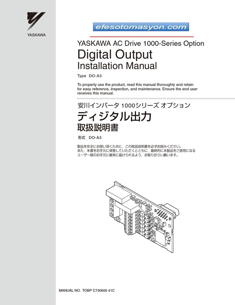
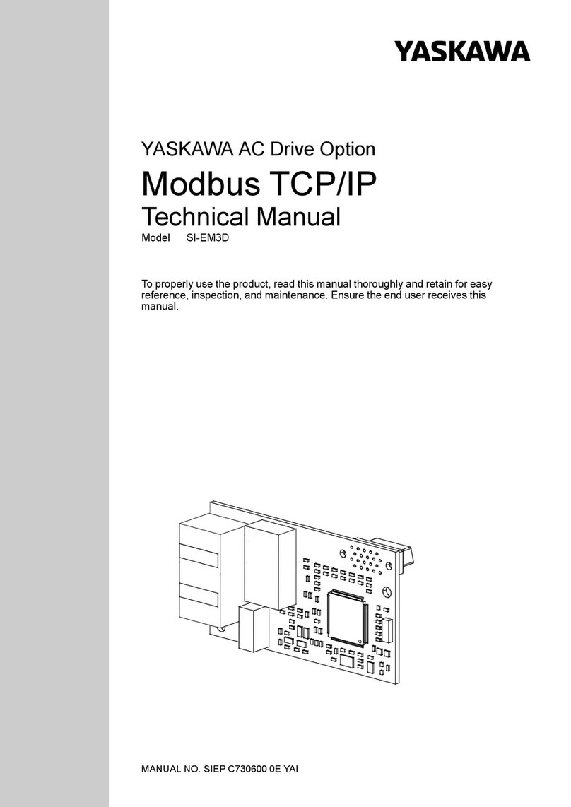
  9. YASKAWA SI-ES3 User manual

YASKAWA SI-ES3 User manual

2YASKAWA ELECTRIC SIEP C730600 64A 1000-Series Option SI-ES3 Technical Manual
Copyright © 2013 YASKAWA ELECTRIC CORPORATION
All rights reserved. No part of this publication may be reproduced, stored in a retrieval system, or transmitted, in any form or by any
means, mechanical, electronic, photocopying, recording, or otherwise, without the prior written permission of Yaskawa. No patent
liability is assumed with respect to the use of the information contained herein. Moreover, because Yaskawa is constantly striving to
improve its high-quality products, the information contained in this manual is subject to change without notice. Every precaution has
been taken in the preparation of this manual. Yaskawa assumes no responsibility for errors or omissions. Neither is any liability
assumed for damages resulting from the use of the information contained in this publication.
YASKAWA ELECTRIC SIEP C730600 64A 1000-Series Option SI-ES3 Technical Manual 3
Table of Contents
1 PREFACE AND SAFETY . . . . . . . . . . . . . . . . . . . . . . . . . . . . . . . . . . . . . . . . . . . . . . . 4
2 PRODUCT OVERVIEW . . . . . . . . . . . . . . . . . . . . . . . . . . . . . . . . . . . . . . . . . . . . . . . . 6
3 RECEIVING . . . . . . . . . . . . . . . . . . . . . . . . . . . . . . . . . . . . . . . . . . . . . . . . . . . . . . . . . 7
4 OPTION COMPONENTS . . . . . . . . . . . . . . . . . . . . . . . . . . . . . . . . . . . . . . . . . . . . . . . 8
5 INSTALLATION PROCEDURE . . . . . . . . . . . . . . . . . . . . . . . . . . . . . . . . . . . . . . . . . 11
6 DSP301 AND DSP402 SPECIFICATIONS. . . . . . . . . . . . . . . . . . . . . . . . . . . . . . . . . 17
7 RELATED DRIVE PARAMETERS . . . . . . . . . . . . . . . . . . . . . . . . . . . . . . . . . . . . . . . 24
8 OBJECT DICTIONARY . . . . . . . . . . . . . . . . . . . . . . . . . . . . . . . . . . . . . . . . . . . . . . . 26
9 CONFIGURING MANUFACTURER SPECIFIC CANOPEN OBJECTS. . . . . . . . . . . 45
10 PROCESS DATA OBJECTS (PDO). . . . . . . . . . . . . . . . . . . . . . . . . . . . . . . . . . . . . . 47
11 DRIVE PARAMETER, MONITOR AND CONTROL REGISTER ACCESS . . . . . . . . 52
12 FAULT DIAGNOSIS AND POSSIBLE SOLUTIONS . . . . . . . . . . . . . . . . . . . . . . . . . 54
13 SPECIFICATIONS . . . . . . . . . . . . . . . . . . . . . . . . . . . . . . . . . . . . . . . . . . . . . . . . . . . 60
4YASKAWA ELECTRIC SIEP C730600 64A 1000-Series Option SI-ES3 Technical Manual
1 Preface and Safety
Yaskawa manufactures products used as components in a wide variety of industrial systems and equipment. The selection
and application of Yaskawa products remain the responsibility of the equipment manufacturer or end user. Yaskawa
accepts no responsibility for the way its products are incorporated into the final system design. Under no circumstances
should any Yaskawa product be incorporated into any product or design as the exclusive or sole safety control. Without
exception, all controls should be designed to detect faults dynamically and fail safely under all circumstances. All
systems or equipment designed to incorporate a product manufactured by Yaskawa must be supplied to the end user with
appropriate warnings and instructions as to the safe use and operation of that part. Any warnings provided by Yaskawa
must be promptly provided to the end user. Yaskawa offers an express warranty only as to the quality of its products in
conforming to standards and specifications published in the Yaskawa manual. NO OTHER WARRANTY, EXPRESS OR
IMPLIED, IS OFFERED. Yaskawa assumes no liability for any personal injury, property damage, losses, or claims
arising from misapplication of its products.
Applicable Documentation
The following manuals are available for the option:
Terms
Registered Trademarks
• EtherCAT is a trademark of Beckhoff Automation GmbH, Germany.
• All trademarks are the property of their respective owners.
Option
Yaskawa AC Drive 1000-Series Option
SI-ES3 EtherCAT Installation Manual
Manual No: TOBP C730600 64
Read this manual first.
The installation manual is packaged with the option and contains
information required to install the option and set up related drive
parameters.
Yaskawa AC Drive 1000-Series Option
SI-ES3 EtherCAT Technical Manual
Manual No: SIEP C730600 64
(This book)
The technical manual contains detailed information about the
option. Access the following sites to obtain the technical manual:
U.S.: http://www.yaskawa.com
Europe: http://www.yaskawa.eu.com
Japan: http://www.e-mechatronics.com
For questions, contact your local Yaskawa sales office or the nearest
Yaskawa representative.
Yaskawa Drive
Yaskawa AC Drive
1000-Series Quick Start Guide
The drive manuals cover basic installation, wiring, operation
procedures, functions, troubleshooting, and maintenance
information.
The manuals also include important information about parameter
settings and drive tuning.
Access these sites to obtain Yaskawa instruction manuals:
U.S.: http://www.yaskawa.com
Europe: http://www.yaskawa.eu.com
Japan: http://www.e-mechatronics.com
Other areas: contact a Yaskawa representative.
Yaskawa AC Drive
1000-Series Technical Manual
Note: Indicates supplemental information that is not related to safety messages.
Drive: Yaskawa AC Drive 1000-Series
Option: Yaskawa AC Drive 1000-Series Option SI-ES3 EtherCAT
NOID: Network Option Interface Driver (Yaskawa Interface driver)
Online-DRV: NOID processing mode, process (ctrl/resp) data is active
Online-PRG: NOID processing mode, NO process (ctrl/resp) data is active
1 Preface and Safety
YASKAWA ELECTRIC SIEP C730600 64A 1000-Series Option SI-ES3 Technical Manual 5
Supplemental Safety Information
Read and understand this manual before installing, operating, or servicing this option. The option must be installed
according to this manual and local codes.
The following conventions are used to indicate safety messages in this manual. Failure to heed these messages could
result in serious or possibly even fatal injury or damage to the products or to related equipment and systems.
General Safety
DANGER
Indicates a hazardous situation, which, if not avoided, will result in death or serious injury.
WARNING
Indicates a hazardous situation, which, if not avoided, could result in death or serious injury.
CAUTION
Indicates a hazardous situation, which, if not avoided, could result in minor or moderate injury.
NOTICE
Indicates an equipment damage message.
General Precautions
• The diagrams in this section may include options and drives without covers or safety shields to illustrate details. Reinstall covers or shields
before operating any devices. The option should be used according to the instructions described in this manual.
• Any illustrations, photographs, or examples used in this manual are provided as examples only and may not apply to all products to which this
manual is applicable.
• The products and specifications described in this manual or the content and presentation of the manual may be changed without notice to
improve the product and/or the manual.
• When ordering new copies of the manual, contact a Yaskawa representative or the nearest Yaskawa sales office and provide the manual number
shown on the front cover.
DANGER
Heed the safety messages in this manual.
Failure to comply will result in death or serious injury.
The operator is responsible for injuries or equipment damage caused from failure to heed the warnings in the manual.
NOTICE
Do not modify the drive or option circuitry.
Failure to comply could result in damage to the drive or option and will void warranty.
Yaskawa is not responsible for any modification of the product made by the user. This product must not be modified.
Do not expose the drive or option to halogen group disinfectants.
Failure to comply may cause damage to the electrical components in the option.
Do not pack the drive in wooden materials that have been fumigated or sterilized.
Do not sterilize the entire package after the product is packed.
6YASKAWA ELECTRIC SIEP C730600 64A 1000-Series Option SI-ES3 Technical Manual
2 Product Overview
2 Product Overview
About This Product
This option provides a communications connection between the drive and an EtherCAT network. The option connects the
drive to an EtherCAT network and facilitates the exchange of data.
This manual explains the handling, installation and specifications of this product.
EtherCAT is a communications link to connect industrial devices (such as smart motor controllers, operator interfaces,
and variable frequency drives) as well as control devices (such as programmable controllers and computers) to a
network. EtherCAT is a simple, networking solution that reduces the cost and time to wire and install factory automation
devices, while providing interchangeability of like components from multiple vendors.
By installing the option to a drive, it is possible to do the following from an EtherCAT master device:
• drive operation
• drive operation status monitoring
• changing parameter settings.
The option provides instant connectivity to an EtherCAT network for the Yaskawa A1000 drive. The option supports the
Velocity mode according the CANopen Device Profile and Motion Control (DSP402) profile. It also contains Yaskawa
vendor specific CANopen objects based on the present CANopen option board specification.
The EtherCAT Option supports the following communication profiles:
• DS 301 Ver. 4.02
• DSP 402 Ver. 3.0 Velocity Mode
Figure 1
Figure 1 EtherCAT Conformance Tested
Applicable Models
The option can be used with the drive models in Table 1.
Table 1 Applicable Models
Drive Series Drive Model Number Software Version <1>
<1> See “PRG” on the drive nameplate for the software version number.
A1000 CIMR-A2A ≥1017
CIMR-A4A
3 Receiving
YASKAWA ELECTRIC SIEP C730600 64A 1000-Series Option SI-ES3 Technical Manual 7
3 Receiving
Please perform the following tasks upon receipt of the option:
• Inspect the option for damage. Contact the shipper immediately if the option appears damaged upon receipt.
• Verify receipt of the correct model by checking the model number printed on the name plate of the option package.
• Contact your supplier if you have received the wrong model or the option does not function properly.
Option Package Components
Table 2 Option Package Contents
Tools Required for Installation
• A Phillips screwdriver (M3 metric/#1, #2 U.S. standard size <1>) is required to install the option and remove drive front
covers.
• Diagonal cutting pliers. (required for some drive models)
• A small file or medium grit sandpaper. (required for some drive models)
Note: Tools required to prepare option networking cables for wiring are not listed in this manual.
Description: Option Ground
Wire Screws (M3) LED Label Installation Manual
_
Quantity: 1131 1
<1> Screw sizes vary by drive capacity. Select a screwdriver appropriate for the drive capacity.
RUN ERR
L/A IN L/A OUT
MANUAL
8YASKAWA ELECTRIC SIEP C730600 64A 1000-Series Option SI-ES3 Technical Manual
4 Option Components
4 Option Components
SI-ES3 Option
Figure 2
Figure 2 SI-ES3 Option Components
Communication Connector
The EtherCAT Option is connected to the network using a RJ45 connector. The pin assignment is explained in Table 3.
Table 3 Communication Connector (RJ45)
A – Connector (CN5) F – LED (L/A IN) <1>
B – Installation hole G – Model number
C – LED (RUN) <1> H – Ground terminal and installation hole <2>
D – LED (ERR) <1> I – Communication connector CN1 (RJ45)
<1> Refer to Option LED Display on page 9 for details on the LEDs.
<2> The ground wire provided in the option shipping package must be connected during installation.
E – LED (L/A OUT) <1> J – Communication connector CN2 (RJ45)
EtherCAT Connector Pin Signal Description
1TD+
Send data
2TD-
3RD+Receivedata
4 – N.C. (Pins denoted as N.C. do not connect to any signal)
5 – N.C. (Pins denoted as N.C. do not connect to any signal)
6RD-Receivedata
7 – N.C. (Pins denoted as N.C. do not connect to any signal)
8 – N.C. (Pins denoted as N.C. do not connect to any signal)
Housing – Shield
Underside
A
Looking from the connector
B
C
D
F E
H
I
J
SI-ES3
G
IN OUT
A1000
8 7 6 5 4 3 2 1
4 Option Components
YASKAWA ELECTRIC SIEP C730600 64A 1000-Series Option SI-ES3 Technical Manual 9
Option LED Display
The EtherCAT Option has four LED displays that indicate the communication status. The indications conform with
DS303, Part 3: Indicator Specification.
L/A IN, L/A OUT
The Link/Activity indicators show the status of the physical link and show activity on the link period
RUN
A green lit EtherCAT RUN LED indicates the status of the EtherCAT network state machine.
A red lit EtherCAT RUN LED is only used by the NOID firmware loader (refer to Table 4).
ERR
The red EtherCAT error LED indicates the presence of any errors.
Table 4 Option LED States
Name Indication Meaning
Color Status
L/A IN
L/A OUT
– Continuously off No link. The communication cable is not physically connected or the EtherCAT
controller is not started up.
Green Continuously on The option is connected to Ethernet. A communication cable is physically connected,
but data is not being exchanged.
Flickering There is traffic on Ethernet. Data is being exchanged.
RUN
– Continuously off The device is in INIT state.
Green
Blinking The device is in Pre-Operational state (flashing rate about 400 ms).
Single flash
The device is in Safe-Operational state.
Single flash is one short flash (approximately 200 ms), followed by a long off phase
(approximately 1000 ms).
Continuously on The device is in Operational state.
Red Blinking (1 Hz or 6 Hz)
The Option BOOT or APP firmware is executing the NOID firmware loader.
1 Hz: Firmware loader protocol is in IDLE state (waiting for commands from the
drive).
6 Hz: Firmware loader protocol is processing commands.
ERR Red
Continuously off No fault. The EtherCAT communication is operating normally.
Blinking General configuration error
Single flash
The slave device application has changed the EtherCAT state autonomously.
The parameter “Change” in the AL status register is set to 0x01: change/error.
Single flash is one short flash (approximately 200 ms), followed by a long off phase
(approximately 1000 ms).
Double flash
The sync manager watchdog time out has occurred.
Double flash is two short flashes (approximately 200 ms each), separated by an off
condition (approximately 200 ms), and then a long off phase (approximately 1000 ms).
Continuously on
Possible causes:
• An EtherCAT PDI (Process Data Interface) error has occurred or the NOID
application interface has failed.
• An option card FATAL event has occurred (System has stalled execution; see
manufacturer specific profile object 0x4000 for cause).
Blinking (1 Hz or 6 Hz)
The option BOOT or APP firmware is executing the NOID firmware loader.
1 Hz: Firmware loader protocol is in IDLE state (waiting for commands from drive).
6 Hz: Firmware loader protocol is processing commands.
4 Option Components
10 YASKAWA ELECTRIC SIEP C730600 64A 1000-Series Option SI-ES3 Technical Manual
Figure 3 explains the indicator flash rates.
Figure 3
Figure 3 LED Flash Rates
DSP402 Functionality
This function manages the DSP402 drive profile functionality in the option and converts the control/status data into drive
specific control/status data.
Vendor Specific CANopen Objects
The vendor specific CANopen object model is integrated into EtherCAT.
Error Management
EtherCAT processes drive and EtherCAT specific errors and assures that all faults process and propagate properly to the
drive/EtherCAT network.
flickering
blinking
single
flash
double
flash
inverted
double
flash
triple
flash
n flashes
on
50
ms
200
ms
200
ms
200
ms
1000
ms
200
ms
200
ms
200
ms
200
ms
200
ms
200
ms
1000
ms
1000
ms
200
ms
off
on
off
on
off
on
off
on
off
200
ms
200
ms
200
ms
200
ms
200
ms
1000
ms
on
off
200
ms
200
ms
200
ms
200
ms
1000
ms
on 12 n
off
5 Installation Procedure
YASKAWA ELECTRIC SIEP C730600 64A 1000-Series Option SI-ES3 Technical Manual 11
5 Installation Procedure
Section Safety
DANGER
Electrical Shock Hazard
Do not connect or disconnect wiring while the power is on.
Failure to comply will result in death or serious injury.
Disconnect all power to the drive and wait at least the amount of time specified on the drive front cover safety label.
After all indicators are off, measure the DC bus voltage to confirm safe level, and check for unsafe voltages before
servicing. The internal capacitor remains charged after the power supply is turned off.
WARNING
Electrical Shock Hazard
Do not remove the front covers of the drive while the power is on.
Failure to comply could result in death or serious injury.
The diagrams in this section may include options and drives without covers or safety shields to show details. Be sure to
reinstall covers or shields before operating any devices. The option should be used according to the instructions
described in this manual.
Do not allow unqualified personnel to use equipment.
Failure to comply could result in death or serious injury.
Maintenance, inspection, and replacement of parts must be performed only by authorized personnel familiar with
installation, adjustment, and maintenance of this product.
Do not touch circuit boards while the power to the drive is on.
Failure to comply could result in death or serious injury.
Do not use damaged wires, place excessive stress on wiring, or damage the wire insulation.
Failure to comply could result in death or serious injury.
NOTICE
Damage to Equipment
Observe proper electrostatic discharge (ESD) procedures when handling the option, drive, and circuit boards.
Failure to comply may result in ESD damage to circuitry.
Never shut the power off while the drive is outputting voltage.
Failure to comply may cause the application to operate incorrectly or damage the drive.
Do not operate damaged equipment.
Failure to comply may cause further damage to the equipment.
Do not connect or operate any equipment with visible damage or missing parts.
Do not use unshielded cable for control wiring.
Failure to comply may cause electrical interference resulting in poor system performance.
Use shielded twisted-pair wires and ground the shield to the ground terminal of the drive.
5 Installation Procedure
12 YASKAWA ELECTRIC SIEP C730600 64A 1000-Series Option SI-ES3 Technical Manual
Prior to Installing the Option
Prior to installing the option, wire the drive, make necessary connections to the drive terminals, and verify that the drive
functions normally without the option installed. Refer to the Quick Start Guide packaged with the drive for information
on wiring and connecting the drive.
Figure 4 shows an exploded view of the drive with the option and related components for reference.
Figure 4
Figure 4 Drive Components with Option
Properly connect all pins and connectors.
Failure to comply may prevent proper operation and possibly damage equipment.
Check wiring to ensure that all connections are correct after installing the option and connecting any other
devices.
Failure to comply may result in damage to the option.
A – Insertion point for CN5 connector H – Included screws
B – SI-ES3 option I – Ground wire
C – Drive front cover J – Option modular connector CN1, CN2
D – Digital operator K – Drive grounding terminal (FE)
E – LED label L – Connector CN5-A
F – Drive terminal cover M – Connector CN5-B
G – Removable tabs for wire routing N – Connector CN5-C
NOTICE
F
H
L
M
N
K
I
BC
D
E
A
G
J
RUN ERR
L/A IN L/A OUT
A1000
5 Installation Procedure
YASKAWA ELECTRIC SIEP C730600 64A 1000-Series Option SI-ES3 Technical Manual 13
Installing the Option
Remove the front covers of the drive before installing the option. Refer to the drive Quick Start Guide for directions on
removing the front covers. Cover removal varies depending on drive size. This option can be inserted only into the
CN5-A connector located on the drive control board.
WARNING! Electrical Shock Hazard. Do not connect or disconnect wiring while the power is on. Failure to comply could result in death
or serious injury. Before installing the option, disconnect all power to the drive and wait at least the amount of time specified on the
drive front cover safety label. After all indicators are off, measure the DC bus voltage to confirm safe level, and check for unsafe
voltages before servicing. The internal capacitor remains charged after the power supply is turned off.
1. Shut off power to the drive, wait the appropriate amount of time for voltage to dissipate, then remove the digital
operator (D) and front covers (C, F). Refer to the Quick Start Guide packaged with the drive for directions on
removing the front covers. Cover removal varies depending on drive size.
NOTICE: Damage to Equipment. Observe proper electrostatic discharge procedures (ESD) when handling the option, drive, and
circuit boards. Failure to comply may result in ESD damage to circuitry.
Figure 5
Figure 5 Remove the Front Covers and Digital Operator
2. With the front covers and digital operator removed, apply the LED label (E) in the appropriate position on the
drive top front cover (C).
Figure 6
Figure 6 Apply the LED Label
C
D
F
A1000
RUN ERR
L/A IN L/A OUT
C
E
A1000
5 Installation Procedure
14 YASKAWA ELECTRIC SIEP C730600 64A 1000-Series Option SI-ES3 Technical Manual
3. Insert the option (B) into the CN5-A connector (L) located on the drive and fasten it using one of the included
screws (H).
Figure 7
Figure 7 Insert the Option
4. Connect the ground wire (I) to the ground terminal (K) using one of the remaining provided screws (H). Connect
the other end of the ground wire (I) to the remaining ground terminal and installation hole on the option (B) using
the last remaining provided screw (H) and tighten both screws to 0.5 to 0.6 Nxm (4.4 to 5.3 in lbs).
Figure 8
Figure 8 Connect the Ground Wire
Note: There are two screw holes on the drive for use as ground terminals (K). When connecting three options, two ground wires will
need to share the same drive ground terminal.
H
B
L
A1000
H
I
K
B
A1000
5 Installation Procedure
YASKAWA ELECTRIC SIEP C730600 64A 1000-Series Option SI-ES3 Technical Manual 15
5. Route the option wiring.
Depending on the drive model, some drives may require routing the wiring through the side of the front cover to
the outside to provide adequate space for the wiring. Refer to the Peripheral Devices & Options section of the
drive Quick Start Guide or Technical Manual for more information on wire routing of specific models.
Route the wiring through the side of the front cover to the outside. In these cases, using diagonal cutting pliers,
cut out the perforated openings on the left side of the drive front cover as shown in Figure 9-A. Sharp edges
along the cut out should be smoothed down with a file or sand paper to prevent any damage to the wires.
Route the wiring inside the enclosure as shown in Figure 9-B for drives that do not require routing through the
front cover.
Note: Separate communication cables from main circuit wiring and other electrical lines.
Figure 9
Figure 9 Wire Routing Examples
6. Connect the EtherCAT communication cable to the option modular connector CN1 and CN2.
To connect the option to a network, insert the RJ45 communication connector of the Cat5e patch cable into the
option modular female connector CN1 and CN2. Ensure the cable end is firmly connected (see Figure 9).
Communication Cable Specifications
Only use cable recommended for EtherCAT. Using a cable not specifically recommended may cause the option
or drive to malfunction.
Connection Diagram
Figure 10 Option Connection Diagram
A – Route wires through the openings provided
on the left side of the front cover. <1>
<1> The drive will not meet NEMA Type 1 requirements if wiring is exposed outside the enclosure.
B – Use the open space provided inside the drive
to route option wiring.
<1> The ground wire provided in the option shipping package must be connected during installation.
B
A
A1000
Drive
M
U
V
W
R
S
T
CN5-A
FE
<1>
EtherCAT Master EtherCAT Cable
MotorPower
SI-ES3
EtherCAT
Option
CN1,
CN2
A1000
5 Installation Procedure
16 YASKAWA ELECTRIC SIEP C730600 64A 1000-Series Option SI-ES3 Technical Manual
7. Replace and secure the front covers of the drive (C, F) and replace the digital operator (D).
Figure 10
Figure 11 Replace the Front Covers and Digital Operator
Note: Take proper precautions when wiring the option so that the front covers will easily fit back onto the drive. Make sure no cables
are pinched between the front covers and the drive when replacing the covers.
8. Set drive parameters in Table 13 for proper option performance.
Network Termination
The EtherCAT network does not require a termination resistor if the drive is the last node in the network. The network is
terminated by the ASIC of the EtherCAT option card.
ESI File
For easy network implementation of drives equipped with an EtherCAT option, the ESI file can be obtained from:
U.S.: http://www.yaskawa.com
Europe: http://www.yaskawa.eu.com
Japan: http://www.e-mechatronics.com
Other areas: Contact a Yaskawa representative
F
C
D
A1000
6 DSP301 and DSP402 Specifications
YASKAWA ELECTRIC SIEP C730600 64A 1000-Series Option SI-ES3 Technical Manual 17
6 DSP301 and DSP402 Specifications
Network communication on EtherCAT is based on the DSP301 communication profile and the CANopen DSP402 device
profile for drives and motion control. This profile specifies mandatory objects that will be implemented as well as
manufacturer specific and optional objects.
Process Data Objects (PDOs) are used for I/O exchange and Service Data Objects (SDO) for explicit messaging. The
time for transmitting PDOs is significantly lower than the time for transmitting SDOs, therefore, communication objects
like command/reference are mapped onto PDOs as standard.
All CANopen communication objects can be accessed via SDOs. The SDOs allow acknowledged access to
communication objects, i.e., the communication adapter confirms the intended access.
Modes
The A1000 series EtherCAT option will support two operating modes:
• DSP402 Velocity mode
DSP402 object 0x6061 (Modes of operation display) = 2
• Automatic vendor specific mode
It is also possible to run the drive by mapping the vendor specific command and status to control the drive. Any access
to the DSP402 Controlword will be rejected.
DSP402 object 0x6061 (Modes of operation display) = -2
Profile/vendor mode is automatically activated by the option within the following constraints:
• If an RxPDO mapping has been assigned to DSP402 Controlword 0x6040 and EtherCAT is in the Safe-Operational
(SAFEOP) or Operational (OP) state, the DSP402 profile will be processed.
• If the EtherCAT state machine is NOT in the SAFEOP or OP state and an SDO write request is performed on the
DSP402 0x6040 Controlword, the DSP402 profile will be processed.
• If the EtherCAT state machine is NOT in the SAFEOP or OP state and an SDO read request is performed on the
DSP402 0x6041 Statusword, the DSP402 profile will be processed.
• Otherwise, the vendor specific Controlword will be accessed normally.
DSP402 Velocity Mode
Many AC drives use this simple mode to control the velocity of the drive with limits and ramp functions.
Vendor Specific Mode (DSP402 profile bypass)
In this mode, the DSP402 state machine processor in the option is bypassed and the drive native control commands and
status are used.
6 DSP301 and DSP402 Specifications
18 YASKAWA ELECTRIC SIEP C730600 64A 1000-Series Option SI-ES3 Technical Manual
Implemented CANopen Objects/Components
Communication and parameters on CANopen are built around objects using the following message types.
• SDO (Service Data Object)
The SDO object uses asynchronous data transmission and is used to access objects without mapping them to an I/O
(PDO) connection. With SDO communication, the user will have access to all CANopen objects in the option.
• Process Data Object (PDO)
The PDO object is used for I/O communication.
• Emergency Object (EMCY)
Emergency object is used for error reporting when a fault has occurred in the drive or option.
Services
Supported SDO Requests
• SDO Download Expedited
Writes up to four octets to the slave
• SDO Download Normal
Writes up to a negotiated number of octets to the slave
• Download SDO segment
Writes additional data if the object size is greater than the negotiated number of octets
• SDO Upload Expedited
Reads up to four octets from the slave
• SDO Upload Normal
Reads up to a negotiated number of octets from the slave
• Upload SDO segment
Reads additional data if the object size is greater than the negotiated number of octets
• Abort SDO Transfer
Server abort of service when error is detected
Emergency Service
• Emergency (Does not support incoming requests)
Report of unexpected conditions
6 DSP301 and DSP402 Specifications
YASKAWA ELECTRIC SIEP C730600 64A 1000-Series Option SI-ES3 Technical Manual 19
EtherCAT State Machine
Figure 11
Figure 12 EtherCAT State Machine
The option enters the INIT state directly after start-up. After this, the option can be switched to the Pre-Operation
(PREOP) state. In the PREOP state, drive parameters can be accessed by CoE SDO.
After the master has configured the slave, the option can be switched to Safe-Operation (SAFEOP) state. In the SAFEOP
state, Input I/O data (PDOs) will be sent from the option to the EtherCAT master, but there may be no void Output I/O
data from the master to the option.
When the transition from PREOP to SAFEOP occurs, the option will process the configured PDO assignments and
re-map the relevant drive registers. After this, the option will enter the SAFEOP state.
In order to communicate Output I/O data, the master must switch the option to Operation (OP) state.
EtherCAT Operation Mode Relations
Table 5 EtherCAT Operation Mode Relations
Note: If the requested drive state cannot be entered due to transition from lower to higher state (the drive might be controlled locally
and reject an application IF state switch), an error will be generated on EtherCAT. The state transition time out wait time is 3
seconds.
EtherCAT state Event Description
INIT State SDO access possible against the drive.
PREOP State
• SDO access possible against the drive.
• No ctrl data is mapped against the drive.
• Only drive status is mapped on resp registers to service the DSP emergency services.
SAFEOP State
• SDO access possible against the drive.
• Input PDO data from “Drive →Option” valid.
• Master output data “Option →Drive” not valid.
OP State
• SDO access possible against the drive.
• Input PDO data from “Drive →Option” valid.
• Master output data “Option →Drive” valid.
PREOP →SAFEOP Trans • Option will re-map required drive registers in NOID.
• Option will trigger INIT request to re-map ctrl/resp registers exchanged in Online-DRV.
SAFEOP →PREOP
SAFEOP →INIT
OP →PREOP
OP →INIT
Trans
• If drive is operating, option will trip drive with bUS error.
• Option will trigger NOID to switch operation mode to Online-PRG.
• Option will remap and clear all ctrl/resp data.
SAFEOP →OP Trans NOID will SET “ctrl data valid bit”
OP →SAFEOP Trans No processing done, only bUS error is set against the drive.
INIT
Pre-Operational
Safe-Operational
Operational
Power ON
(IP)(PI)
(SP)(PS)
(OP)
(OI)
(SI)
(SO) (OS)
6 DSP301 and DSP402 Specifications
20 YASKAWA ELECTRIC SIEP C730600 64A 1000-Series Option SI-ES3 Technical Manual
DSP402 State Machine
The CANopen DSP402 specification indicates the state machine of the drive. Since the DSP402 adapter is external to the
inverter, the whole state machine must be implemented in the option card itself.
CANopen DSP402 Controlword/Statusword
This section describes how to control the drive via Controlword/Statusword and how to access drive parameters.
Table 6 Controlword
Table 7 Statusword
Controlword Operation Mode Specific Bits in Velocity Mode
Table 8 Controlword Operation Mode Specific Bits in Velocity Mode
Bit Number Controlword Application Reference/CPI Function Calls
0 Switch on This bit controls the DS402 state machine - See Table 10
1 Enable voltage This bit controls the DS402 state machine - See Table 10
2 Quick stop This bit controls the DS402 state machine - See Table 10
3 Enable operation This bit controls the DS402 state machine - See Table 10
4 Operation mode specific Please see Table 8 for more details
5 Operation mode specific Please see Table 8 for more details
6 Operation mode specific Please see Table 8 for more details
7 Fault reset This bit controls the DS402 state machine - See Table 10
8 Halt Not implemented
9 Operation mode specific Please see Table 8 for more details
10 Manufacturer specific NA
11 Manufacturer specific NA
12 Manufacturer specific NA
13 Manufacturer specific NA
14 Manufacturer specific NA
15 Manufacturer specific NA
Bit Number Statusword Drive Reference
0 Ready to switch on This bit controls the DS402 state machine - See Table 11
1 Switched on This bit controls the DS402 state machine - See Table 11
2 Operation enabled This bit controls the DS402 state machine - See Table 11
3 Fault This bit controls the DS402 state machine - See Table 11
4 Voltage enabled 1: High voltage is applied to the drive
5 Quick stop This bit controls the DS402 state machine - See Table 11
6 Switch on disabled This bit controls the DS402 state machine - See Table 11
7 Warning 1: During alarm condition
8 Manufacturer specific NA
9 Remote 1: Controls the frequency reference or the run command from the option
0: Does not control the frequency reference or the run command from the option
10 Target reached (Op mode spec) See Table 9
11 Internal limit active 0: Always, not implemented
12 Operation mode specific Refer to Table 9 for more details
13 Operation mode specific Refer to Table 9 for more details
14 Manufacturer specific NA
15 Manufacturer specific NA
Bit Number Controlword Drive Reference
4rfgenable
0: Does not control the frequency reference from the option
1: Controls the frequency reference from the option
5 rfg unlock 0: Discards any new NET set-point
1: Uses new NET set-point
6 rfg use ref 0: Forces NET set-point to zero
1: Uses NET set-point
9 Not implemented Not implemented

Other manuals for SI-ES3

2

Other YASKAWA Control Unit manuals

YASKAWA SPEED7 CPU-SC 313-5BF23 User manual

YASKAWA

YASKAWA SPEED7 CPU-SC 313-5BF23 User manual

YASKAWA MP2000 Series User manual

YASKAWA

YASKAWA MP2000 Series User manual

YASKAWA System 300S+ CPU 315-4PN43 User manual

YASKAWA

YASKAWA System 300S+ CPU 315-4PN43 User manual

YASKAWA CANopen SI-S3/V User manual

YASKAWA

YASKAWA CANopen SI-S3/V User manual

YASKAWA VIPA System SLIO User manual

YASKAWA

YASKAWA VIPA System SLIO User manual

YASKAWA CANopen SI-S3 User manual

YASKAWA

YASKAWA CANopen SI-S3 User manual

YASKAWA JEPMC-OP3C01-E User manual

YASKAWA

YASKAWA JEPMC-OP3C01-E User manual

YASKAWA V1000 SI-EM3D/V User manual

YASKAWA

YASKAWA V1000 SI-EM3D/V User manual

YASKAWA VIPA SLIO FM 050 User manual

YASKAWA

YASKAWA VIPA SLIO FM 050 User manual

YASKAWA VIPA SPEED7 User manual

YASKAWA

YASKAWA VIPA SPEED7 User manual

YASKAWA MECHATROLINK Sigma 2 Series User manual

YASKAWA

YASKAWA MECHATROLINK Sigma 2 Series User manual

YASKAWA VIPA System 200V User manual

YASKAWA

YASKAWA VIPA System 200V User manual

YASKAWA S-V Series User manual

YASKAWA

YASKAWA S-V Series User manual

YASKAWA CM006 User manual

YASKAWA

YASKAWA CM006 User manual

YASKAWA VIPA System SLIO User manual

YASKAWA

YASKAWA VIPA System SLIO User manual

YASKAWA FM 054 User manual

YASKAWA

YASKAWA FM 054 User manual

YASKAWA Varispeed f7 User manual

YASKAWA

YASKAWA Varispeed f7 User manual

YASKAWA SI-EP3/V User manual

YASKAWA

YASKAWA SI-EP3/V User manual

YASKAWA S-II Series User manual

YASKAWA

YASKAWA S-II Series User manual

YASKAWA 62K-JJK0 User manual

YASKAWA

YASKAWA 62K-JJK0 User manual

YASKAWA motoman NX100 User manual

YASKAWA

YASKAWA motoman NX100 User manual

YASKAWA Profibus-DP SGDH Series User manual
YASKAWA

YASKAWA Profibus-DP SGDH Series User manual

YASKAWA CM085 User manual

YASKAWA

YASKAWA CM085 User manual

YASKAWA MP2000 Series User manual

YASKAWA

YASKAWA MP2000 Series User manual
Popular Control Unit manuals by other brands

Bristan OP TS1503 CL C Installation instructions and user guide

Bristan

Bristan OP TS1503 CL C Installation instructions and user guide

Moxa Technologies MiiNePort W1 Series Quick installation guide

Moxa Technologies

Moxa Technologies MiiNePort W1 Series Quick installation guide

ICPDAS IR-712A user manual

ICPDAS

ICPDAS IR-712A user manual

impro technologies HMW701-0-0-NN-XX installation manual

impro technologies

impro technologies HMW701-0-0-NN-XX installation manual

Bosch CCU-Modul Important information

Bosch

Bosch CCU-Modul Important information

Genebre 2272 Installation, operation and maintenance manual

Genebre

Genebre 2272 Installation, operation and maintenance manual

Baxi MONOGIRO NT Series Assembly instructions

Baxi

Baxi MONOGIRO NT Series Assembly instructions

IBASE Technology ET876 Series user manual

IBASE Technology

IBASE Technology ET876 Series user manual

GMV GreenLift 3010 2CH A3 Installation, use and maintenance manual

GMV

GMV GreenLift 3010 2CH A3 Installation, use and maintenance manual

Domestia DME-LAN-002 user manual

Domestia

Domestia DME-LAN-002 user manual

NuAire CM-XBOX-INLINE installation manual

NuAire

NuAire CM-XBOX-INLINE installation manual

Sparklan WPEQ-261ACNI user manual

Sparklan

Sparklan WPEQ-261ACNI user manual

Watts LF007 Series INSTRUCTION, INSTALLATION, MAINTENANCE AND REPAIR MANUAL

Watts

Watts LF007 Series INSTRUCTION, INSTALLATION, MAINTENANCE AND REPAIR MANUAL

Honeywell SOMAT39 user manual

Honeywell

Honeywell SOMAT39 user manual

Quick TCD 2044 Installation and use manual

Quick

Quick TCD 2044 Installation and use manual

Faraday 8706 INSTALLATION INSTRUCTIONS AND WIRING

Faraday

Faraday 8706 INSTALLATION INSTRUCTIONS AND WIRING

NI PXIe-7975 Getting started

NI

NI PXIe-7975 Getting started

praher Aquastar Comfort 1001 manual

praher

praher Aquastar Comfort 1001 manual

manuals.online logo
manuals.online logoBrands
  • About & Mission
  • Contact us
  • Privacy Policy
  • Terms and Conditions

Copyright 2025 Manuals.Online. All Rights Reserved.