5
There are LED indicators (one blue LED and one red LED) next to the line
connectors. The blue LED lights up when the pushbutton (PB) for the line is pressed;
the red LED lights up when there is a short circuit on the latter.
2. ELECTRICAL CONNECTION 1
The DME-LAN-002 card is powered directly by the 230 VAC mains. The input voltage
range is 100–240 VAC and 50–60 Hz.
From the DME-LAN-002 card, the identification modules are connected via two
wires.
There is no polarity to consider. They can be wired either:
• by bus.
• in a star or triangle configuration.
• both, simultaneously.
Figure A below shows the DME-LAN-002 with the connection principle for the
dierent outputs:
• Slave cards can be connected to the DME-LAN-002, via the RS485 bus to
terminals 6(A), 7(B), 8(GND) (RS485 Slave). In order to do this, use the UTP
cable (recommended), the VVT cable or the VOB cable, etc. To create a link
between remote cards in dierent boxes, it is best to use a UTP cable, with a
pair for terminal 6(A) and 7(B) and a pair for terminal 8 (GND).
• Terminals 1, 2 and 3 (RJ45) make it possible to connect the DME-LAN-002
card to the Ethernet network directly to a DET-005-002 touch screen, or via a
network switch to allow the DET-005-002 touch screen, smartphone or tablet
to access the home-automation system. Use a UTP Cat5e cable (minimum).
• The DMCT-001-001 temperature sensors are connected to terminals 27–31
(«RS485 Captor»and «16V Captor». The power supply for the latter is
provided by the DME-LAN-002). Use a UTP cable (recommended), a VVT
cable or a VOB cable, etc.
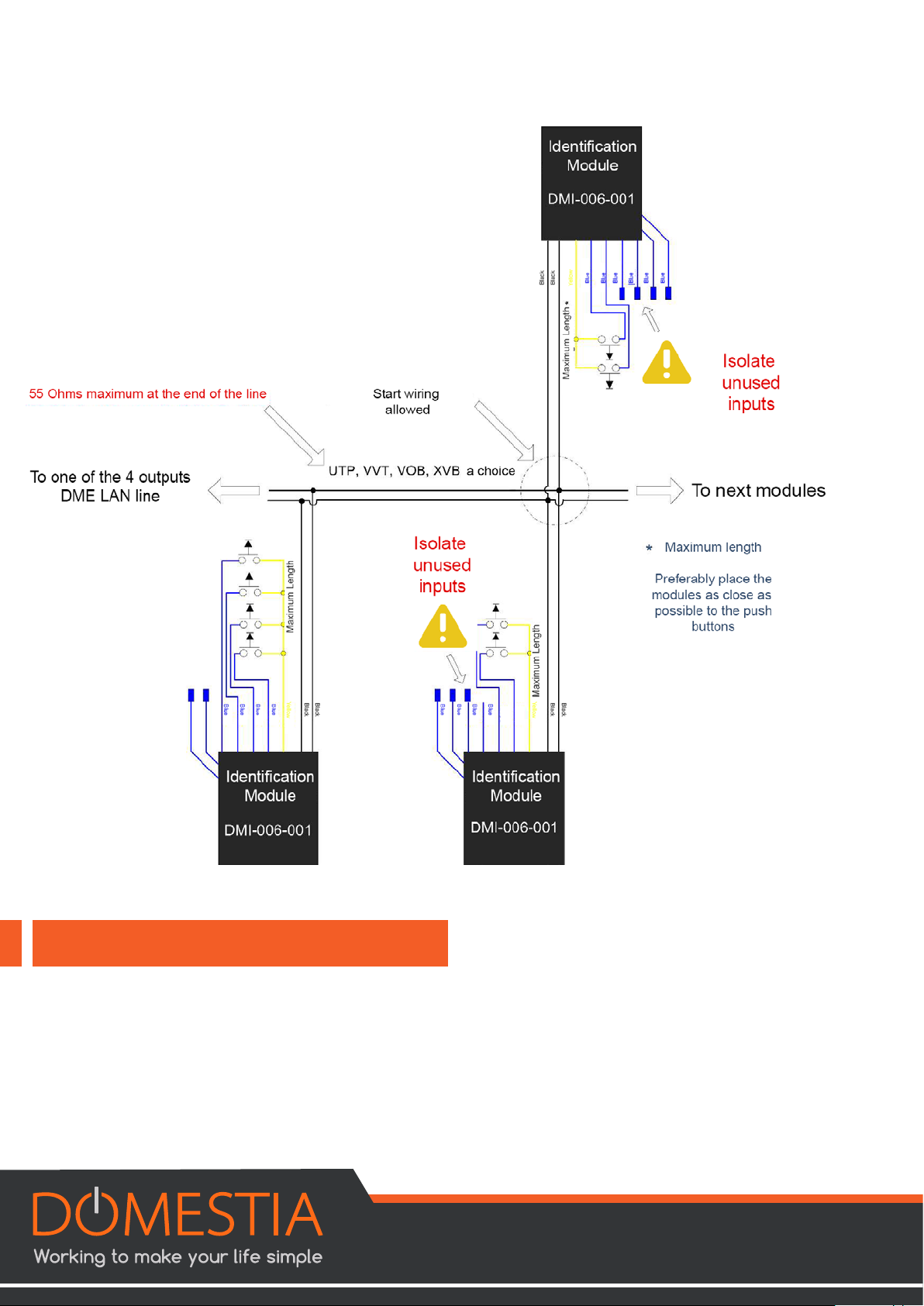
• As explained in chapter 2, the identification modules are connected on the
«Line» inputs. Each «Line» input can be used to program a maximum of 60
dierent functions. It is preferable to divide the modules into several circuits
over 4 lines. Wiring the identification modules: Two non-polarised wires (UTP,
VVT, XVB, VOB, etc). (Be careful of the quality of the connection: the cross-
section of the identification module wires is 0.6mm²).
• The 230 VAC power supply is connected to terminals 24(L) and 26(N)