1. RATINGS AND SPECIFICATIONS
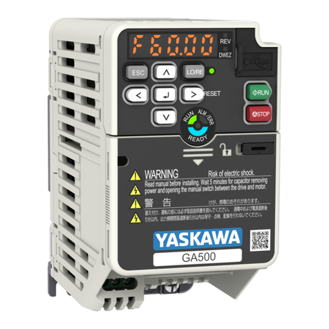
1.1 SERVOPACK RATINGS AND SPECIFICATIONS
Table1.1 SERVOPACK Ratings and Specifications
SERVOPACK Types CPCR- MR01 C MR01 CJ MR02C MR02CJ MR05C MR07C
Motor Output kW 0.1 max 0.1 0.2 0.2 0.5 0.77
Control Method Single-phase bridge rectifying (power transformer installed separately), transistorized PWM control
Main Voltage Single-phase, 200/220VAC +10% or 100/110VAC _10%, 50/60Hz ---1_5%
Power Circuit Capacity* kVA 0.3 0.3 0.5 0.5 1 1.5
Supply
Control Circuit Single-phase, 100/110VAC _+-_10%, 50/60Hz, 50VA (with power transformer installed separately)
MaxOutput VoItage (V MAx) VDC -----30 (at +-6A)--1,100 (at+-3A)___45 (at +-7A)--1,100 (at_--+6A) +85 (at _8A)--1.80 (at +-13A)
Instantaneous Max Output _--t-15_+ 10% _+ 11 -+ 10% _+20_+ 10% ___15--1. 10% --1, 20 -t- 10% __.30--1, 10%
Current (IMAX) A
Continuous Output Current (I out)A--1.6 _--t-3 --1,7 +6_+ 8 --1,13
Current Limiting RangeA +-3 to +-15 +1 to_+11 +-3 to +-20 +3 to +-15 +-3 to _20 +-6 to ±30
Waveform Factor 1.05 and below
Derating Factor 0.95 and below
Speed Control Range 1000 : 1
Load Regulation 0 to 100% 0.1% and below at rated speed, -t-0.05% and below at 1/1000 rated speed
Voltage Regulation --+10% --1,0.1% and below at rated speed, --1,0.02% and below at 1/1000 rated speed
Temperature Regulation --1,0.5% and below at rated speed, --1,0.1% and below at 1/1000 rated speed
25-+35°0
con- Tach-gen(TG) Temperature _0.05%/oC
Regulation
Rated Reference Voltage +-6VDC (forward running at plus reference)
-o _ - Resistance 20k_2+ 10%
u_ rr__ Circuit Time Constant 35/_s ___20%
Rated Reference Voltage --1.2 to -+10 V
"5 Resistance 3.3 k_l/V
Circuit Time Constant 45/_s and below
Speed Feedback DC tachometer generator feedback control (7V/1000r/min)
Built-in Reference Power Supply --1.12VDC, -+30mA
Ambient Temperature -- 10"C to +60°C (-- 10°C to +40°C in panel)
Storage Temperature --20°C to -t-60=C
Humidity 85% and below (non-condensing)
Print motor standard series,Minertia motor: 3 times motor inertia
Allowable Load Inertia Cup motor, Hi-cup motor, Minertia motor J series: 2 times motor inertia
*Forratedoutput Notes:
fused for application at a rated reference voltage other than -t-6 V. 1. Make sure that the power voltage is limited to less than 220 V +10 %
(242 V). For voltages higher than 220 to 242 V, use a step down trans-
Type Designation former to reduce the voltage.
CPCR-M R i_-][_-]C[_-] - [_-] 2. Thedrive characteristicoftypeCPCR-MR[]]C differs forServopoc_$ and
"--_ T applicablemotors as shown inFig. 1.1 (a)and(b). Theallowable
/
L
current-conduction time for the instantaneous rating depends on com-
_!ar_e_s_A_d Servomotor tobe Applied binations with the applicable motor and is guaranteed only for time of
• Blank: Standard Motor (Cup Motor) start and stop (approx. ls or _ess) in the allowable inertia
:oi_rlo_i_ I/PWM See Table 1.2. range. An overload protection suchas motor locking is therefore
rsing " J: Minertia Motor J Series (JM) necessary depending on the application conditions.
• M: Minertia Motor Standard
Series(MM) 3. When a servomotor is driven by thyristor drive units, the armature
• H: Hi-Cup Motor (HM) current generally pulsates, differing from that of battery-driven units.
• 08: 0.75kW •C: Cup Motor(CM) This reduces the average value (component to "produce torque) of ar-
• 15: 1.5 kW • P: Print Motor (PM) mature current when the motor rated current equals armature current
•22: 2.2 kW (r/min), and therefore, it is necessary to reduce the rated torque for the
• 55: 5.5kW Optional motor.
•75: 7.5kW
•99: 9.9 kW •Blank: Standard type Thereduction rate is termed the derating factor. The derating
• W_: Externally ventilatingfan typefactorof ServopacktypeCPCR-MR[]]C isvery excellent, 95%or greater.
Design Revision Order • L: Built-in overload detection typeExample: When typeCPCR-MR[]C or 95 % derating factor is com-
- J: Overspeed drive type for JM binedwith a motor ofratedoutput 1.5kW(8.183N.m), the effective
•C: SecondRevision • Y[]]: Special order output(torque) is1.5kW(8.183N.m)X0.95(14.25kW).
tType CPCR-MR[]]C and TypeCPCR-MR[]]CW differ inthe shapesand4. In the speed control range,the lowest speed is definedunderthe con-
cooling systems. For ventilatingconstruction with overload detection dition not stopped by 100 % load variation.
circuit, the type CPCR-MR[]]CWL is applied. 5. Speed regulation is generally defined as follows:
No load speed-- Full load speed
Speed regulation =×100 96
4Rated speed
