2.Performance
Test conditions:
Temperature and humidity: 23°C ±5°C at 80% RH or below
Accuracy: ±(percentage of reading + number of digits)
Note: Each response noted below is a value measured in the Range Hold mode.
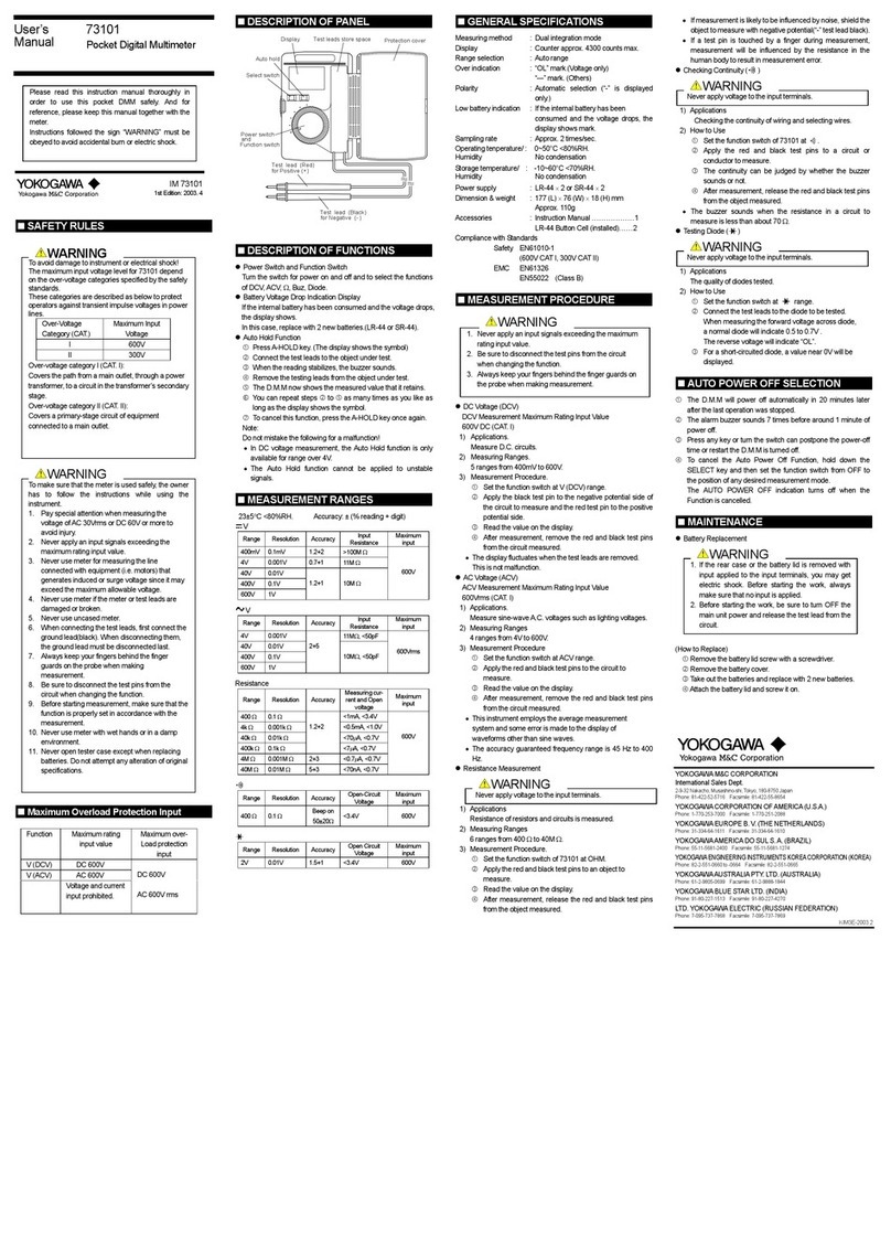
•DC Voltage Measurement ( V)
400 mV 0.1 mV 10 MΩ
4V 0.001 V 11 MΩ1000 V DC
40 V 0.01 V 0.3% + 1 0.2% + 1
1000 Vrms AC
400 V 0.1 V 10 MΩ
1000 V 1 V
Range Resolution Input
Resistance Maximum
Input Voltage
Accuracy
733 01 733 02 & 733 03
Normal mode rejection ratio: 60 dB or better at 50/60 Hz
Common mode rejection ratio: 120 dB or better
Response: 1 sec maximum
•AC Voltage Measurement ( V)
(733 01) - AC coupling. Based on mean-value
detection and root-mean-square value calibration.
400 mV 0.1 mV 10 MΩ, <50 pF
4V 0.001 V 11 MΩ, <50 pF 1000 VDC
40 V 0.01 V 0.5% + 2 1% + 2 1.5% + 4 1000 Vrms AC
400 V 0.1 V 10 MΩ, <50 pF
1000 V 1 V
Range Resolution Input Impedance Maximum Input
Voltage
Accuracy
50/60 Hz 40 - 500 Hz 500 -1 kHz
Common mode rejection ratio: 60 dB or better at DC to 60 Hz AC frequencies (where Rs = 1 kΩ)
Response: 2 sec maximum
•AC Voltage Measurement ( V) (733 02)
- AC coupling. Based on mean-value
detection and root-mean-square value calibration.
400 mV 0.1 mV 10 MΩ, <50 pF
4V 0.001 V 11 MΩ, <50 pF 1000 VDC
40 V 0.01 V 0.5% + 2 0.75% + 2 1.5% + 4 1000 Vrms AC
400 V 0.1 V 10 MΩ, <50 pF
1000 V 1 V
Range Resolution Input Impedance Maximum Input
Voltage
Accuracy
50/60 Hz 40 - 500 Hz 500 -1 kHz
Common mode rejection ratio: 60 dB or better at DC to 60 HzAC frequencies (where Rs = 1 k
Ω
)
Response: 2 sec maximum
•AC Voltage Measurement ( V) (733 03) - AC coupling. Based on root-mean-
square value detection and mean-value detection (excluding 400 mV range)
and root-mean-square value calibration (excluding 400 mV range).
400 mV 0.1 mV 10 MΩ, <50 pF
4V 0.001 V 11 MΩ, <50 pF 1000 VDC
40 V 0.01 V 0.5% + 5 1% + 5 1.5% + 5 1000 Vrms AC
400 V 0.1 V Note Note Note 10 MΩ, <50 pF
1000 V 1 V
Range Resolution Input Impedance Maximum Input
Voltage
Accuracy
50/60 Hz 40 - 500 Hz 500 -1 kHz
Common mode rejection ratio: 60 dB or better at DC to 60 HzAC frequencies (where Rs = 1 k
Ω
)
Response: 2 sec maximum
Crest factor: < 3
Note: 5 to 100% of the full scale and 1000 V range is 200 to 1000 V.
•DC Current Measurement ( A)
µA 400 µA 0.1 µA <0.11 mV/µA
4000 µA1µA1% + 2
mA 40 mA 0.01 mA <2.5 mV/mA
400 mA 0.1 mA 0.5% + 2
A4A 0.001 A
10 A 0.01 A 1.2% + 2 <0.1V/A
Range Resolution Voltage Drop Maximum Input
Current
Accuracy
733 01
733 02 & 733 03
400 mA
The input is
protected by a
500 mA/600 V
fuse.
10 A
The input is
protected by a
15 A/600 V fuse.
Response: 1 sec maximum
•AC Current Measurement ( A) (733 01) - AC Coupling. Based on mean-value
detection and root-mean-square value calibration.
µA 400 µA 0.1 µA <0.11 mV/µA
4000 µA1µA1% + 5
mA 40 mA 0.01 mA <2.5 mV/mA
400 mA 0.1 mA 1.5% + 5
A4A 0.001 A
10 A 0.01 A 1.2% + 5 <0.1 V/A
Range Resolution Voltage Drop Maximum Input
Current
Accuracy
50/60 Hz
40 -1 kHz
400 mA
The input is
protected by a
500 mA/600 V
fuse.
10 A
The input is
protected by a
15 A/600 V fuse.
Response: 2 sec maximum
•AC Current Measurement ( A) (733 02 & 733 03) - AC Coupling. Based on root-
mean-square value calibration (733 03) and mean-value detection and root-
mean-square value calibration.
µA 400 µA 0.1 µA <0.11 mV/µA
4000 µA1µA 0.75% + 5
mA 40 mA 0.01 mA Note 1.5% + 5 <2.5 mV/mA
400 mA 0.1 mA Note
A4A 0.001 A 1% + 5
10 A 0.01 A Note <0.1 V/A
Range Resolution Voltage Drop Maximum Input
Current
Accuracy
50/60 Hz
40 -1 kHz
400 mA
The input is
protected by a
500 mA/600 V
fuse.
10 A
The input is
protected by a
15 A/600 V fuse.
Response: 3 sec maximum
Crest factor: < 3 (733 03)
Note: 5 to 100% of the full scale and 10 A range is 2 to 10 A (733 03).
•Resistance Measurement (Ω)
400 Ω0.1 Ω<1.4 mA <3.4 V
4 kΩ0.001 kΩ0.5% + 1 0.4% + 1 <120 µA
40 kΩ0.01 kΩNote Note <13 µA600 Vrms
400 kΩ0.1 kΩ<1.3 µA<1.3 V
4 MΩ0.001 MΩ0.5% + 1 <130 nA
40 MΩ0.01 MΩ1% + 2
Range Resolution Accuracy Measuring
Current
Open-loop
Voltage Input Protective
Voltage
733 01
733 02/03
Response: 2 sec maximum for ranges lower than the 400 kΩrange; 10 sec maximum for
ranges higher than 4 MΩ
Note: Readings in the 400 Ωrange are the values after zero calibration has been completed.
•Continuity Check ( )
400 Ω0.1 Ω0.8 mA <3.4 V 600 Vrms
Range Resolution Range of Operation
Measuring Current Open-loop
Voltage Input Protective
Voltage
The buzzer turns on
for resistances lower
than 20 Ω.
•DiodeTest ( )
2 V 0.001 V 1% + 2 About 0.5 mA <3.4 V 600 Vrms
Range Resolution Accuracy
Measuring Current
(Vf = 0.6 V)
Open-loop
Voltage Input Protective
Voltage
•Temperature measurement (TEMP)
-50.0°C to 150°C 0.1°C
(-58.0°F to 302.0°F) (0.1°F) 600 Vrms
Range Resolution Input Protective VoltageAccuracy
±1°C for 0°C to 70.0°C range;
(±1.8°F for 32°F to 158°F range)
±2°C for -30.0°C to 0°C range
and 70.0°C to 150.0°C range.
(±3.6°F for -22°F to 32°F range
and 158°F to 302°F range)
Accuracy is the value when measured in combination with the 2349-01 (optional).
•Capacitor Check ( )This function is not supported on the 733 01 multimeter.
10 nF 0.01 nF
100 nF 0.1 nF 600 Vrms
1000 nF 1 nF 2% + 5
10 µF 0.01 µF
100 µF 0.1 µF3% + 5
1000 µF1µF
Range Resolution Input Protective VoltageAccuracy
733 02 & 733 03
2% + 10
Readings are the values after zero
calibration has been completed.
•Frequency measurement (Hz) This function is not supported on the 733 01
multimeter.
10.00 to 99.99 Hz 0.01 Hz 0.2 to 400 Vrms
90.0 to 999.9 Hz 0.1 Hz 0.02% + 1 600 Vrms
900 to 9999 Hz 1 Hz 0.4 to 400Vrms
9.00 to 99.99 k-Hz 0.01 kHz 0.8 to 100Vrms 100 Vrms
Range Resolution Input Voltage Maximum Input
Voltage
Accuracy
733 02 & 733 03
AC Coupling
•Capacitor Check ( )
CAUTION
To avoid damage to instrument
Turn off the power to the circuit under test before starting measurement in order to pre-
vent any excess voltage from being applied to the multimeter.
a) Turn the function switch from the OFF position to the position.
b) Plug the black testing lead into the COM input terminal and the red testing lead into the •
V • Ω• input terminal.
c) Open the testing lead and press the SELECT key to adjust the stray capacitance to zero (the
display shows 0.00).
d)
Connect the testing leads to the capacitor under test and then read the meter when it stabilizes.
When the capacitor check is below the capacity at zero calibration, “0.00” is displayed until
the power off.
NOTE
Do not mistake the following for a malfunction!
Zero calibration is only effective when the 10 nF range is selected.
•Frequency Measurement (Hz)
CAUTION
To avoid damage to instrument
Check which mode the function switch is set to before starting measurement.
a) Turn the function switch from the OFF position to the V position.
b) Press the SELECT key to select Hz measurement (the display shows the Hz symbol).
c) Plug the black testing lead into the COM input terminal and the red testing lead into the •
V • Ω• input terminal.
d) Connect the testing leads to the circuit under test and then read the meter when it stabilizes.
NOTE
Do not mistake the following for a malfunction!
If the Frequency measurement range is selected and the testing leads are left open-circuited,
the multimeter may give some kind of reading. This does not affect your measurement.
AUTO HOLD Function
The 733 series of multimeters can automatically retain the measured value when the testing
leads are handled as described below.
a) Press the D-H/A-H key to select the function. (The display shows the
A • H
symbol.)
b) Connect the testing leads to the object under test.
c) When the reading stabilizes, the buzzer sounds.
d) Remove the testing leads from the object under test.
e) The multimeter now shows the measured value that it retains.
f) You can repeat steps b) to e) as many times as you like as long as the display shows the
A • H
symbol.
g)
To cancel this function, press the D-H/A-H
key
once again. (The
A • H
symbol disappears.)
NOTE
Do not mistake the following for a malfunction!
•In DC/AC voltage measurement, theAUTO HOLD function is only available for ranges
greater than the 4 V range.
•
This function is not available for capacitor Check andTemperature-mode measurement.
•The AUTO HOLD function cannot be applied to unstable signals.
REL&% Calculation Function
The 733 series of multimeters can calculate relative values or differences, and percentage values
from the reference measurement values.
(1) REL calculation
Subtracts the reference value from the measured value to display the relative value or difference.
a) Enter the reference value.
b) Press the REL/% key to display the
REL
symbol.
c) Enter the measured value.
d) The display shows the relative value or difference.
(2) % calculation
Calculates and displays the percentage value according to the following equation:
% value = (reference value - measured value)/ reference value
a) Enter the reference value.
b) Press the REL/% button to display the
REL
symbol.
c) Enter the measured value.
d) Press the REL/% button again to display the % symbol.
e) The display shows the percentage value.
AUTO POWER OFF function
The multimeter automatically turns off if no key is pressed for a period of 20 minutes. The
multimeterwillbeepfor approximately 30secondstoalert the operatorbeforetheAUTOPOWER
OFF function takes effect. (Pressing any key while the multimeter is beeping postpones the
power-off time.) Pressing any key once after the power to the multimeter is automatically
turned off switches the multimeter on again.
To cancel the AUTO POWER OFF function, hold down the D-H/A-H key and then turn the
function switch from OFF to the desired position of any measurement mode. (The AUTO
POWER OFF indication turns off when the function is canceled.)
To enable the function once again, temporarily turn the function dial back to the OFF position,
and then select the desired measurement mode.
a
b)
c)
When this function is complete, turn the function switch back to the OFF position and turn-off
the multi meter.
Battery Replacement
If the batteries fall below the normal operating voltage, the symbol turns on. If this
happens, replace the batteries with new ones (two AA-size [R6 or LR6] batteries).
CAUTION
To avoid electric shock
•Be SURE to disconnect the multimeter from the circuit under test before replacing the
batteries.
•
Replace both batteries at the same time making sure to position their polarities correctly.
To replace the batteries:
a) Remove the four screws on the back of the casing.
b) Open the casing.
c) Take the battery holder out of the casing.
d) Replace the batteries with new ones and install the battery holder
back into the casing.
e) Close the casing and fasten it with the four screws.
Fuse Replacement
If a current greater than the rated value flows when the multimeter is in the current-measure-
ment range, a protection fuse may blow. If this happens, replace that fuse. The multimeter
contains the following two types of fuses:
• F1 fuse: type A1518EF (600 V/500 mA)
• F2 fuse: type A1519EF (600 V/15A)
CAUTION
To avoid electric shock
•
Be SURE to disconnect the multimeter from the circuit under test before replacing the fuse(s).
•Do NOT operate the multimeter with the casing left open.
•In order to avoid damage to the multimeter or any possible accident, use fuses of the
specified rating.
To replace the fuse(s):
a) Remove the four screws on the back of the
casing.
b) Open the casing.
c) Removetheblownfuse from thefuseholder.
d) Install a new fuse in the holder.
e) Close the casing and fasten it with the four
screws.
Specifications
1. Standard Specifications
• Measurement functions: AC voltage, DC voltage,AC current, DC current, resistance, conti-
nuity, diode, temperature, frequencyNote and capacitanceNote
Note: This function is not supported on the 73301 multimeter.
• Additional functions: Data-hold/Automatic-hold, manual range selection, REL/%, over-
range alarm, and automatic power-off
• Display: LCD display that is capable of indicating a significant reading of up
to 4000 countsNote in the digital display and 40 segments in the bar
graph display along with the indications of the unit indication is
given for positive polarity. The display also has the OL over-range
and low-battery alarm indicators.
Note: The most significant reading is 9999 counts for the frequency
measurement.
• Range selection: Manual or automatic
• Measurement cycle: Digital 2.3 times per second (where the cycle for frequency mea-
surement is once every second and 0.2 to 2 times every second for
capacitor measurement). Bar graph 23 times per second
• Operating temperature range: -10°C to 50°C (with guaranteed accuracy of 23°C ±5°C) with
no condensation
Where, the range is -10°C to 40°C for a humidity of 80%RH or
below, and 40°C to 50°C for a humidity of 70%RH or below.
• Temperature coefficients: Add (accuracy ×0.1)/°C at -10°C to 18°C or 28°C to 50°C
• Storage temperature and humidity ranges: -20°C to 60°C; 70% RH maximum
• Power supply: AA-size (R6 or LR6) batteries: 2
• Battery life: Approximately 1000 hours (733 01), 350 hours (733 02 & 733 03)
• External dimensions: 85 (W) ×191 (H) ×40 (D) mm (excluding protrusions)
• Weight: Approx. 450 g (including batteries)
• Safety standards: EN61010-1; 1993+A2; 1995, EN61010-2-031; 1994
(AC/DC 600V CAT.III,AC/DC 1000V CAT.II, Pollution degree 2)
• EMC standards: EN55011; 1998 Group1 Class B
EN61326-1; 1997+A1; 1998
• Effect of radiation immunity: Accuracy range of reading: [Rated accuracy + 8% of each
range] for the strength of a radio-frequency electromagnetic field of
3 V/m
• Operating altitude: Up to 2000 m above sea level.
• Withstand voltage: 5.55 kVAC 1 minute (between input terminal and casing)
• Accessories: Batteries: 2
Testing leads (RD031): 1 set
Instruction manual: 1
• Optional Accessories: Thermistor measuring probe (2349-01)
F1: Type A1518EF
(600 V/500 mA)
protection fuse
F2: Type A1519EF
(600 V/15 A)
protection fuse View with the Casing Open
Calibration and Maintenance
Calibration Cycle
It is recommended that the instrument be calibrated once a year.
(see also “User Calibration Function.”)
For Inquiry of Servicing and Calibration of Instrument
Please contact one of the Yokogawa M&C sales office or the sales representative from which
you purchased the instrument.
YOKOGAWA M&C CORPORATION
International Sales Dept.
2-9-32, Nakacho, Musashino-shi, Tokyo, 180-8750 Japan
Phone: 81-422-52-5716 Facsimile: 81-422-55-8954
