i
IM 701430-51E
Disk No. DL19
2nd Edition: Sep. 2002 (YK)
All Rights Reserved, Copyright © 2001 Yokogawa Electric Corporation
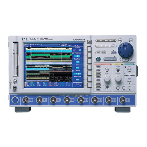
Thank you for purchasing the DL7200 Digital Oscilloscope with the CAN Bus Signal
Analysis Function. This user’s manual describes only the Can Bus analysis function.
For information about other functions, operating procedures, and handling precautions of
the DL7200, see the following manuals:
Manual Title Manual No. Description
DL7100/DL7200 IM701410-01 Explains all functions and procedures of the
User’s Manual DL7100/DL7200 excluding the communication functions.
DL7100/DL7200GP-IB IM701410-11 Describes the communication functions of the
Interface User’s Manual communication interface.
DL7100/DL7200 IM701410-02 Explains only the basic operations of the instrument.
Notes •The contents of this manual are subject to change without prior notice as a result of
improvements in the instrument’s performance and functions. The figures given in
this manual may differ from the actual screen.
•Every effort has been made in the preparation of this manual to ensure the accuracy
of its contents. However, should you have any questions or find any errors, please
contact your nearest YOKOGAWA dealer as listed on the back cover of this manual.
•Copying or reproducing all or any part of the contents of this manual without the
permission of Yokogawa Electric Corporation is strictly prohibited.
•Aguarantee card is attached to the instrument. The card will not be reissued, so
please read it carefully and keep it in a safe place.
CAN Bus Signal Analysis Function
CAN stands for Controller Area Network. It is a serial communication protocol standardized
internationally by the ISO (International Organization for Standardization).
In communications that use CAN, analysis of the physical layer of the CAN Bus is required when
troubleshooting problems that occur due to noise caused by surge voltage and level fluctuations
caused by excessive load after connection. By using this function, data can be analyzed while
displaying the signal waveforms on the CAN Bus as analog waveforms. In addition,
synchronized monitoring of the data on the bus and the analog waveform is possible.
The CAN Bus signal analysis function consists of the following four functions.
•Trigger Function
Acquires signals using the Identifier and Data values of the CAN Bus frame as trigger
conditions. Triggers can also be activated according to the frame type.
•Waveform analysis function
Displays the Identifier and Data values of the acquired waveform in hexadecimal or
binary notation for each frame. Frame type, error type, and other information can also
be displayed simultaneously. Stuff bits can also be detected. The analysis results
can be output to a file in ASCII format.
•Search function
You can search data that match a specified data pattern (dominant, recessive,
indefinite data) and display the result.
•Field Jump function
The beginning of the waveform of the specified field can be displayed.
Trademarks •Adobe and Acrobat are trademarks of Adobe Systems Incorporated.
•PostScript is a registered trademark of Adobe Systems Incorporated.
•Other company and product names are trademarks or registered trademarks of their
respective companies.
Revisions •First Edition July 2001
•Second Edition September 2002
