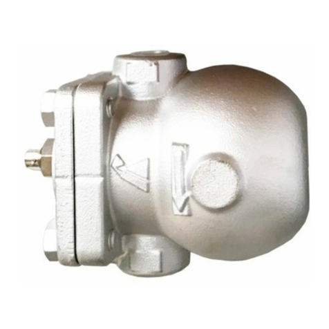
Yoshitake SY-20-10 User manual

■EPDT-147b■
TYPE SY-20
STRAINER
Installation & Operation Manual
We thank you very much for using the Yoshitake Products. In order to put in
use our product correctly and safely, please make sure to read this manual
thoroughly prior to the installation. Also we kindly request you to keep this
manual with care at your hand.
The following safety symbols are used in this manual.
Warning
Indicates that mishandling this product might cause fatal or
serious bodily injury.
Caution
Indicates that mishandling this product might cause bodily
injury or material damage.
Table of Contents
1. Overview ············································································1
2. Specifications······································································1
3. Dimensions and Weights ····················································1
4. Operation·············································································2
5. Pressure loss
5.1. Stainer of diameter·····················································3
5.2. Selection of pipe diameter············································3
5.3. Pressure loss diagram ···················································4
6. Installation
6.1. Example of piping ···························································5
6.2. Precautions during installation and inspection ···········5
7. Operating Procedure
7.1. Precautions during operation and inspection··············6
8. Maintenance Procedure
8.1. Troubleshooting ·····························································7
8.2. Precautions during maintenance and inspection ········7
8.3. Disassembly Procedure·················································7
8.4. Assembly Procedure ·····················································8
8.5 Assembly·········································································8
8.6 Exploded drawing ····························································8

-1- ■EPDT-147b■
1.Overview
Used in wide range of purpose as dust removing from water and oil. Mainly
used for cooling water and water for industrial use.
2.Specifications
Type
SY-20-10
SY-20-20
Connection
JIS 10K RF
JIS 20K RF
Nominal Size
15A~150A
Application
Steam・Air・Cold and hot water・Oil・Other non-dangerous fluids
Maximum Pressure
1.0MPa
2.0MPa
Maximum Temperature
260℃
Material
Body
SCPH2
Screen
SUS304
Screen
Perforated
plate
φ6-1.8 holes/cm2
Element
80 mesh
・20~60Mesh Screen are also available.
Caution
(1) Please collate with attached nameplate and specification of ordered model.
※Please consult factory in case they do not match each other.
3.Dimensions and Weights

-2- ■EPDT-147b■
4.Operation
The screen③removes dust, scale and other foreign matter out of the fluid flown
from inlet port of strainer.
SY-20-10 (mm)
Size
L
H1
Screen
d
Plug
Weight
(kg)
ds
ls
15A
160
104
25
65.5
15
R 3/8
3.0
20A
160
113
30
71.5
20
R 3/8
3.7
25A
180
122
33
76.0
25
R 3/8
4.8
32A
240
154
55
105.0
40
R 1/2
8.0
40A
240
154
55
105.0
40
R 1/2
8.0
50A
260
174
57
112.0
50
R 1/2
10.5
65A
275
187
74
130.0
65
R 1/2
14.3
80A
290
241
90
163.0
80
R 3/4
18.3
100A
362
280
114
187.0
100
R 3/4
34.2
125A
420
330
140
224.5
125
R 3/4
46.3
150A
520
386
184
308.5
150
R 3/4
75.1
SY-20-20 (mm)
Size
L
H1
Screen
d
Plug
Weight
(kg)
ds
ls
15A
160
104
25
56.5
15
R 3/8
3.2
20A
160
113
30
67.5
20
R 3/8
4.0
25A
180
122
33
75.0
25
R 3/8
5.9
32A
240
154
55
101.0
40
R 1/2
9.3
40A
240
154
55
101.0
40
R 1/2
9.3
50A
260
174
57
114.5
50
R 1/2
13.0
65A
275
187
74
124.0
65
R 1/2
15.8
80A
360
241
90
167.0
80
R 3/4
28.0
100A
362
280
114
187.0
100
R 3/4
37.8
125A
415
330
140
224.5
125
R 3/4
57.0
150A
520
386
184
308.5
150
R 3/4
82.8
№
Name of Parts
1
Body
2
Cover
3
Screen
4
Gasket
5
Stud Bolt
6
Nut
7
Plug
8
Name Plate

-3- ■EPDT-147b■
5.Pressure loss
To use the strainer most effectively and to fulfill the required criteria thoroughly,
please take the following points into consideration.
5.1 Selection of strainer diameter
The same one as the piping size is selected(piping size=strainer size) if a small
size is used,pressure drop glows and pressure prescribed at the entrance of the
equipment might not be able to be maintained.
5.2 Selection of pipe diameter
When selecting the nominal diameter of pipe, it is necessary to consider the kind of
fluid, its maximum flow rate, allowable pressure loss and piping installation cost
among others. Smaller diameter of pipe makes the lower piping cost, but the
pressure loss will be increased and there are possibilities of abrasion of pipe, noise
and vibration due to turbulent flow. If the pipe diameter is too large, not only the
piping cost but also the heat loss will be increased.
As one method of selection of suitable pipe diameter, Japan Industrial Standard
(JIS) sets the standard flow velocity depends on the relative kind of fluid, its
characteristic and pipe diameter, to which please refer.
≪Standard flow velocity of fluid≫
Fluid
Standard flow velocity
Water ,Oil
2 m/s(2~4)
Steam
30 m/s(20~40)
※This list shows the standard flow velocity of relative fluid, which made
in reference with the standard of JIS F7101(Ship’s Machinery Standard
Flow Velocity in Pipes).

-4- ■EPDT-147b■
5.3 Pressure loss diagram (Fluid Water)
Screen:Perforated plateφ6.0-1.80holes/cm2 Element 80mesh

-5- ■EPDT-147b■
6.Installation
6.1 Example of piping
6.2 Precautions during installation and inspection
Warning
(1) Because of heavy weight, hold the valve with lifting equipment while
piping. Refer to “3. Dimensions and weights”table for the valve weight.
※Failure to do so may result in injury due to dropping the valve.
Caution
(1)When installing, confirm if the direction of fluid flow matches with inlet and
outlet port of the product respectively.
※If installed in opposite direction, it will not function as designed.
(2)Carry out the securing of pipes and the product properly.
※Excessive piping stress may cause the deformation of strainer.
(3)When installing, reserve the space shown in Figure-4 for the maintenance and
checking (cleaning of the screen).
※It will be impossible to carry out the maintenance and inspection (cleaning of
the screen).
(4)Do not apply excessive load, torque or vibration to the valve.
※The fluid may leak from strainer.
(5)Carry out the connection with pipes properly.
※Improper piping connection may cause the leakage of fluid due to vibration
or other cause. With some kind of fluid, there will be a danger of personnel
being scalded.
※The fluid flowed out of pipe end may cause some material damages.
(1)In case installing pressure gauge at backward and forward of strainer, clogging
can be checked by differential pressure.[Ref.6.1.Example of piping figure 1]
(2)Install strainer with the cap parts facing downward. [Ref.6.1.Example of
piping figure 1]However, install strainer with cap parts facing sideways in
case of steam piping so that condensate accumulation is minimized.[Ref.6.1.
Example of piping figure2]
(3)If fluid flows from bottom to top, install a blow valve in order to remove scale
accumulated at the bottom of riser pipe.[Ref.6.1.Example of piping figure 3]
Figure-1
Figure-2
Figure-3

-6- ■EPDT-147b■
Figure-4
7.Operating Procedure
7.1 Precautions during operation and inspection
Warning
(1)Prior to letting the fluid run in the system, make sure that there is no danger
when the fluid flows out of pipe end.
※In case the fluid of high temperature flows out of pipe end, there will be a
danger of personnel being scalded.
※The fluid flowed out of pipe end may cause some material damages.
(2)Do not tighten the cap and the cover after flowing the fluids to the valve.
※The gasket will be broken and leads to have a leakage.
Caution
(1)Use the strainer in condition of maximum pressure loss of below 0.1MPa. Also
keep cleaning the screen periodically.
※The screen may be damaged.
(mm)
Size
H
15A
146
20A
158
25A
170
32A
223
40A
223
50A
248
65A
276
80A
342
100A
393
125A
467
150A
585

-7- ■EPDT-147b■
8.Maintenance Procedure
8.1 Troubleshooting
Trouble condition
Cause of trouble
Countermeasure and
remedy
No fluid flows.
1.Screen③is clogged up.
2.Stop valves at inlet and/or
outlet side are shut.
1.Disassemble and
clean the screen③.
2.Open stops valves.
Pressure loss is
excessive.
1.Screen③is clogged up.
2.Pressure gauge is damaged.
1.Disassemble and
clean the screen③.
2.Renew the Pressure
gauge
Outer leakage
accure
1.Gasket have deterioration.
1.Replace the gasket.
8.2 Precautions during maintenance and inspection
Warning
(1) Completely discharge internal pressure from the strainer, lines, and equipment,
and cool the strainer down to a level where you can touch it with bare hands
before disassembly and inspection.
※Failure to do so may result in injury or burns due to residual pressure or
spillage around the product.
(2) In case the high temperature of fluid is applied, keep the bare hand off the
strainer.
※It may cause the personnel being scalded.
(3) Since the screen is heavy in weight, when extracting the screen from the body,
make sure to secure it properly with lifting devices.
※The screen fallen down may cause the injury.
8.3 Disassembly Procedure
(1)After confirming that the remaining pressure is relieved from the strainer, remove
the bolts⑥from the cover②and the gasket④, and remove the cover②from
the body①. Extract the screen③from the body①and clean it with compressed
air or cleanser.

-8- ■EPDT-147b■
8.4 Assembly Procedure
Caution
(1) When re-assembling, fix the relative parts properly.
※Parts may be deformed or damaged.
(2) Tighten the bolts evenly on each bolt in turn of diagonal position.
※The fluid may leak from strainer. If the fluid is of high temperature, the leakage may
cause being scalded.
(1)When tighten the nut⑥,Please confirm That
apicalpart of stud bolt⑤will Come out from
flange and nut⑥.
8.5 Assembly
Clean the gasket contacting surface of the body①and cap②and fit a new gasket
④to the cap fit the screen③to the body①and the Cap②before tightening the nut.
8.6 Exploded drawing
Prepare as ConSumable Supplies for
the parts indicated with
①Body
③Screen
⑤Stud Bolt
④Gasket
②Cover
⑥Nut
⑦Plug
Must come
outfrom flange
Must come out
from the nut

2015.8
PDD-046e
Warranty Information
1. Limited warranty
This product has been manufactured using highly-advanced techniques and subjected to
strict quality control. Please be sure to use the product in accordance with instructions on
the manual and the label attached to it.
Yoshitake warrants the product to be free from any defects in material and workmanship
under normal usage for a period of one year from the date of receipt by the original user, but
no longer than 24 months from the date of shipment from Yoshitake’s factory.
2. Parts supply after product discontinuation
This product may be subject to discontinuation or change for improvement without any prior
notice. After the discontinuation of the product, Yoshitake supplies the repair parts for 5
years otherwise individually agreed.
3. This warranty does not cover the damage due to any of below:
(1) Valve seat leakage or malfunction caused by foreign substances inside piping.
(2) Improper handling or misuse.
(3) Improper supply conditions such as abnormal water pressure/quality.
(4) Water scale or freezing.
(5) Trouble with power/air supply.
(6) Any alteration made by other than Yoshitake.
(7) Use under severe conditions deviating from the design specifications
(
e.g. in case of corrosion due to outdoor use).
(8) Fire, flood, earthquake, thunder and other natural disasters.
(9) Consumable parts such as O-ring, gasket, diaphragm and etc.
Yoshitake is not liable for any damage or loss caused by malfunction or defect of the product.
INTERNATIONAL DEPT.
955-5, Miyamae, Irukadeshinden, Komaki, Aichi, 485-0084, Japan
Phone: +81-568-75-4432 Fax: +81-568-75-4763
E-mail: Intntl@yoshitake.co.jp
This manual suits for next models
1
Table of contents
Other Yoshitake Industrial Equipment manuals

Yoshitake
Yoshitake SU-50 User manual

Yoshitake
Yoshitake SY-10 Series User manual

Yoshitake
Yoshitake TRAP STAR TSF-10CF User manual

Yoshitake
Yoshitake DS-1 User manual

Yoshitake
Yoshitake Trap Star TSF-13 User manual

Yoshitake
Yoshitake TRAP STAR TSF-8 User manual

Yoshitake
Yoshitake TRAP STAR TSF-10 User manual

Yoshitake
Yoshitake PG-2 User manual

Yoshitake
Yoshitake SCV-2 User manual

Yoshitake
Yoshitake Trap Star TSF-8AT User manual