Yoshitake TD-10NA User manual

■EPDT-079d■
Model TD-10NA
Model TD-30NA
STEAM TRAP
Instruction Manual
Please read this instruction manual thoroughly before using the steam trap, so that you may do so
correctly and safely. Please carefully store this manual in a handy place.
――――――The following safety symbols are used in this manual.――――――
Warning
This symbol indicates a potentially hazardous situation that, if not avoided,
could result in death or serious injury.
Caution
This symbol indicates a hazardous situation that, if not avoided, may result in
minor or moderate injury. (“Caution” may also be used to indicate other unsafe
practices or risks of property damage.)
Contents
1. Features·························································1
2. Specifications···················································1
3. DimensionsandWeights·····································1
4. Operation·······················································2
5. SelectionofNominalSize····································3
6. Installation······················································3
6.1. Warning and Caution for Installation··············· 3
6.2. ExampleofPiping·······································4
7. OperatingProcedure·········································6
7.1. Warning and Caution for Operation················ 6
8.MaintenanceProcedure·····································7
8.1. Warning and Caution for Maintenance ············ 7
8.2. Troubleshooting···········································7
8.3. Disassembly and Assembly Procedure·············· 8
8.4. DisassemblyDrawing ··································9
9.Disposal·························································9

■EPDT-079d■
-
1
-
Steam trap is the important device for a heat control. A heat control can not be carried out without this device. It has a high
performance and simple structure, and the maintenance is very easy. TD-10NA, TD-30NA steam trap is a disc type which has
various excellent features; thus, it can be used in various ways, such as for a heating system, general industrial use, removing
condensate in piping, and so forth.
1.
Features
(1) Since the product uses a bimetal, it can remove any air trouble, and it also immediately discharges cold water
and air which are generated when it starts up. Therefore, it can start up steam devices efficiently.
(2) Made of stainless steel with a special heat-treated disc and valve seat, providing excellent durability.
(3) Disc and valve seat can easily be replaced on the site without removing the body from the pipe.
(4) The movable part is just a singular disc, thus permitting easy maintenance with its simple structure.
(5) Though compact, lightweight and economical, the operating pressure range is considerably wide, calling for
no adjustment.
(6) Any installation angles, horizontal, inclined or vertical are available, permitting easy piping.
(7) Thetrapiskeptwarmwith insulationcover,which safeguardsitfrommalfunctionorsteam leakage.
(8) Strainer is built-in the steam trap.
(9) Even with its compact size, it features a large discharge capacity.
2.
Specifications
Model Connection Operating
pressure Application Max.
temperature Materials
Body Disc,Valve seat
TD-10NA
JIS Rc or NPT 0.035~2.0MPa
Condensate 220℃ FCD450
Stainlesssteel
TD-30NA
JIS 20KFF
JIS 10KFF 0.035~1.0MPa
※ Permissible back pressure: Less than 50%of inlet pressure.
※ Standard screen: 60 mesh.
Caution
(1)
Please confirm that the indications on the product name plate coincide with the specifications
of the ordered product model before usage.
※In case they do not coincide, do not use the product and contact us.
3.
Dimensions and Weights
・TD-10NA ・TD-30NA
・TD-10NA (mm)
Size d L H
1
H
2
Weight
(kg)
15A Rc 1/2 or NPT 1/2
90 49
55.5
0.9
20A Rc 3/4 or NPT 3/4
90 53
60.5
1.2
25A Rc 1 or NPT 1 90 56
62.5
1.4
・TD-30NA (mm)
Size Flange d L H
1
H
2
Weight
(kg)
15A JIS 10KFF
JIS 20KFF
15
125 51
59 2.3
20A 20
140 54
63 3.4
25A 25
150 65
63 4.1

■EPDT-079d■
-
2
-
※ Flange thickness for JIS 10KFF model is same as JIS 20KFF.
4.
Operation
(1) Beginning of the operation
At the beginning of the operation, the bimetal is still cool.
Thus, the disc is lifted up by the bimetal and ring.
The air and condensate, which are inflowing from the
inlet side, are smoothly discharged to the outlet side; thus,
there is no air trouble to be worried.
(2) Valve closing operation
When steam inflow, the bimetal is heated up and it is
expanded and widely opened. Then, it slips down the
slope of the valve seat, and the ring comes lower than the
seating surface of the valve seat. When the condensate
temperature becomes almost equal to the saturated steam
temperature, the condensate passing through the bottom (A)
of the disc becomes re-evaporating jet. Because of this, a
low-pressure section is generated at section (A).
Furthermore, a part of the jet enters the control chamber
and increases the pressure inside the chamber. As a result,
the disc is pushed down and makes the valve closed.
(3) Condensate inflow
When condensate inflows, the temperature drops, and the
steam inside the control chamber is condensed. Then, the
pressure inside the chamber becomes low.
(4) Valve opening operation
When the pushing-down force becomes less than the
pushing-up force from the jetting-out port at the top of the
valve seat, the disc is opened, and condensate is discharged.
*After this stage, (2), (3) and (4) is continuously repeated.

■EPDT-079d■
-
3
-
0
100
200
300
400
500
600
700
800
900
100 0
110 0
120 0
0 0.2 0 .4 0.6 0.8 1 1 .2 1.4 1.6 1.8 2
O p eratin g D ifferential P ressu re (M P a )
W:Discharge Capacity(kg/h)
15A,20A,25A
5.
Selection of Nominal Size
(1) Select the trap which shows the safety factor 4~5 for an actual use. That is, when discharge capacity of 100 kg/h is
needed, it is economical to use the trap which has the performance of 400~500 kg/h.
(2) You must consider back pressure in order to select the discharge capacity because the trap discharge
condensate according to a difference (operating differential pressure) between the inlet pressure and the outlet
pressure (back pressure). For example, when the inlet pressure is 1.0MPa and the outlet pressure is 0.2MPa,
these are the discharge capacity for operating differential pressure of 0.8MPa.
Max. Continuous Discharge Capacity
6.
Installation
6.1 Warning and Caution for Installation
Warning
(1)Plumb in the piping of the outlet side to the safe place where blowing steam condensate can not affect.
※It is dangerous if fluid blows out.
Caution
(1) Remove foreign matter and scales from the lines before connecting the valve.
※Failure to do so may prevent the valve from functioning correctly.
※ Be sure not to make sealing agent or seal tape go into pipe.
(2) When installing, confirm if the direction of fluid flow matches with inlet and outlet port of the product
respectively.
※If installed in opposite direction, it will not function as designed.
(3) Carry out the securing of pipes and the product properly.
※If exert excessive stress to the valve, it may result in malfunction.
(4) Do not disassemble the trap unreasonably.
※ Disassembling the trap at your discretion may affect the original performance.
(5) When installing, secure the space for the maintenance and checking (cleaning of the screen).
※ It is needed to carry out the maintenance and inspection (cleaning of the screen).

■EPDT-079d■
-
4
-
TD-10NA TD-30NA
(6) Carry out the connection with pipes properly.
※Improper piping connection may cause the leakage of fluid.
(7) Do not use a quick-operating valve in front and behind of trap not to produce water hammer.
※ Trap can be damaged.
(8) Install a trap lower position as possible to collect condensate.And keep piping slope.
(9) Do not insulate the product.
(10) When installing a trap on main pipe of steam, prepare drip leg before the trap.
(11) Install a trap where atmosphere temperature is lower than discharging condensate has.
(12) By-pass line provided in parallel to the trap can give such advantages as follows.
・Byopening the by-pass valve, large volume of condensate and air on start up can bequicklydischarged.
・Newly installed piping can be blown off easily by closing the valves on the inlet and outlet sides and by
opining the by-pass valve.
・ Inspection of a trap and replacement of parts can be done without stopping the line operation.
6.2 Example of piping
Description
Correct
Incorrect
When installing by-pass
line, prepare stop valve
to the outlet si e of a
trap.
Steam trapping near a
regulating valve shall be
provi e to the inlet
si e.
(mm)
X Y Z
TD-10NA
90 90 70
TD-30NA

■EPDT-079d■
-
5
-
Description
Correct
Incorrect
Con ensate from the
steam main shall be taken
out from the bottom.
Trap shall be positione
at the bottom of con ensate
pro ucing evice.
Con ensate from every
evice shall be trappe
in epen ently.
The inlet an outlet
piping shall be the same
nominal size as a nominal
size of the trap.
※
If there is a ifference between
the nominal size of the trap
an piping, inlet pressure
rops, or back pressure rises.

■EPDT-079d■
-
6
-
Description
Correct
Incorrect
The size of collecting
condensate pipe should
be larger than the sum
area of each discharge
pipe.
And install check valves
for prevention of back
flow.
For condensate recovery,
connect condensate pipe to
the top of return pipe.
Install individual return
pipe for each pressure.
And install check valves
for prevention of back
flow.
※Flash steam out from the high
pressure line increases back
pressure of the trap on the low
pressure line.
En of trap ischarge
pipe shall be positione
above the water level in
the pit.
※While stopping the trap may
suction irty water in the pit,
which may lea to malfunction.
7.
Operating Procedure
7.1 Warning and Caution for Operation
Warning
(1) Before flow the steam in pipe line, make sure steam can flow without any dangerous at the end of pipe line.
※In case steam blow off, it may result in burns.
(2) When confirming product’s operation, do not stand in front of outlet. Large amount of condensate may be
discharged at the first steam flow.
※Blowing out of condensate can burn or injure you.
Do not tighten the cap after flowing the fluids to the valve.
(3) Please do not tighten the cap.
※The gasket will be broken and leads to have a leakage.

■EPDT-079d■
-
7
-
8.
Maintenance Procedure
8.1 Warning and Caution for Maintenance
Warning
(1) Do not touch the trap directly with bare hands.
※Doing so may result in burns.
(2) Trap shall be disassembled and inspected by qualified person or manufacture.
※Request the maintenance to specialized dealer or manufacture in case of any problems.
(3) Remove all internal pressure of the product, piping, and equipment before disassembly and inspection. And
cool down the product.
※Residual pressure in the product or piping can result in burns.
Caution
(1) Inspect a product daily.
※ It is needed to maintain the original performance.
(2) In case of no operation for a long period, perform operating examination before start operation again.
※ Failure to do so may malfunction by rust in the products and piping.
(3) Put a container under the products at disassembly since condensate may flow out.
※ In case of no container for condensate, it makes dirty surrounding of the trap.
(4) Take care not to fall parts down during the disassembly. Use soft cloth; put disassembled parts on it not to
make scratches them.
※Failure to do so, original performance may be affected.
(5) Secure tight assembly of all parts.
※Failure to do so may malfunction or leakage to outside.
(6) When repair the product, proper parts must be used. And do not alter product.
※Using the improper parts and alternation of the product may be result on injury or burns by breakage of
product, blowing out of steam or condensate, or malfunction.
(7) Replace gaskets with new ones when reassembling.
※The gasket is consumable parts. Reuse of gaskets may cause steam leakage problem.
(8) With leakage problem such as continuous blowing out of condensate by existence foreign matters
between valve and valve seat, contact us or our agent since disassemble, repair or replace of parts may be
needed.
(This leakage problem by the customer using is not under our warranty.)
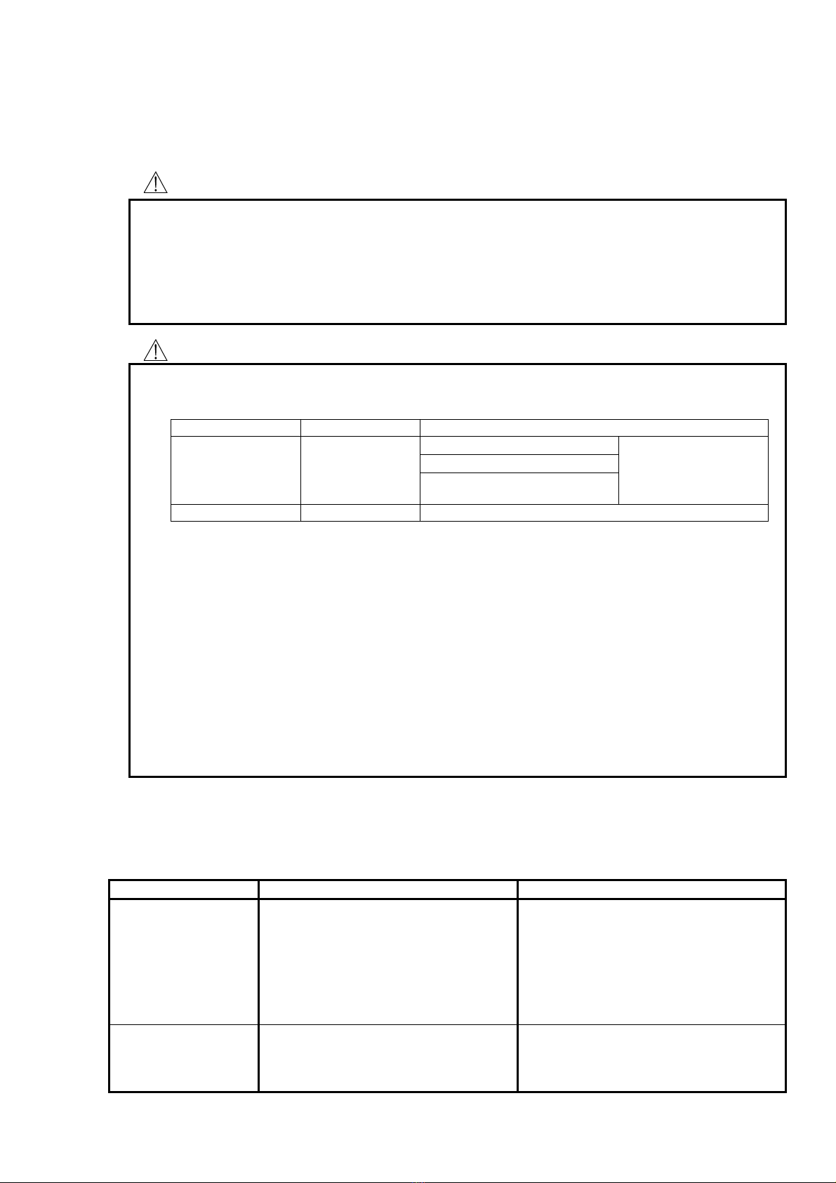
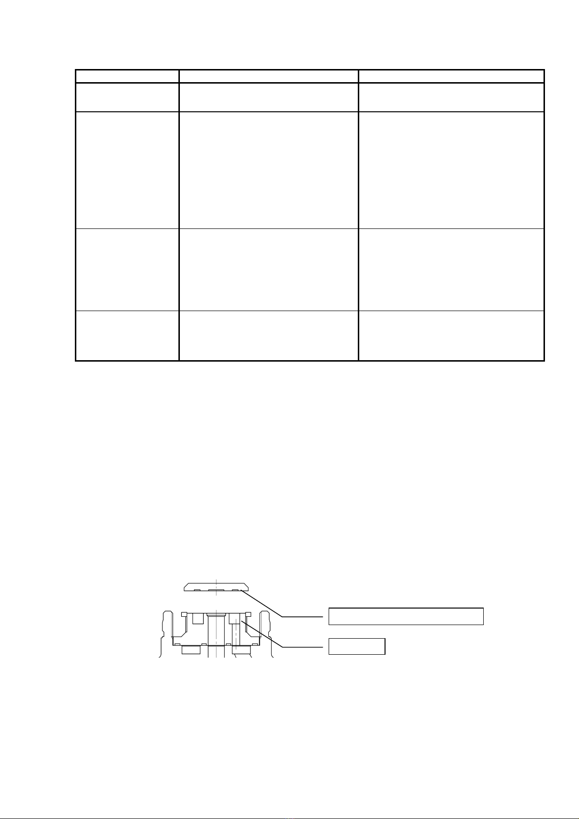
8.2 Troubleshooting
Problem Cause Solution
Condensate is not
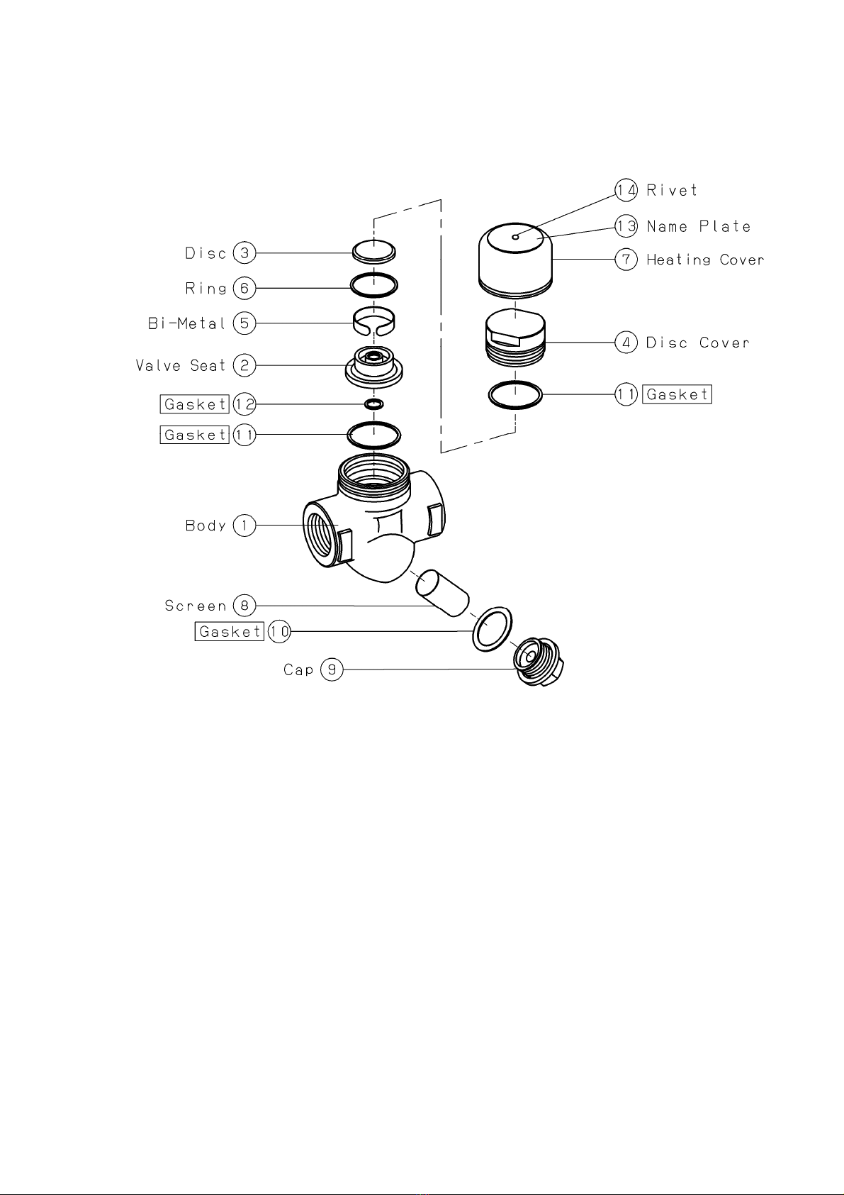
Discharged. 1. Blockage in a discharge hole of valve
seat②. 1. Disassemble and clean it.
2. Screen⑧is clogging. 2. Disassemble and clean it.
3. Breakage as a result of abnormal
pressure rising such as freezing or
water hammer.
3. Replace the trap.
Improper discharge. 1. Operating differential pressure of the
trap is not high enough. 1. Examine the inlet/outlet pressure o
f the
trap.
2. The screen⑧is clogging. 2. Disassemble and clean it.
Daily inspection
Item Inspecting way Troubleshooting
Discharge of
condensate
Visual inspection
(1)No condensate discharge
Refer to 8.2
Troubleshooting.
(2) Poor condensate discharge
(3)
Continuous discharge
of
condensate or steam.
Leakage to outside Visual inspection
Refer to 8.2 Troubleshooting.

■EPDT-079d■
-
8
-
Problem Cause Solution
Improper discharge. 3. There may be a tendency of steam
locking. 3. Examine the piping system.
Continuous blow-out. 1. Foreign matter stuck to disc③and
valve seat②.
1. Disassemble and clean it.
2. Scratches or wear on the disc③
or
valve seat②.
2. Replace the parts.
3. Exceeding over the permissible back
pressure. 3. Examine the piping system.
4. The pressure on use is less than the
minimum operating pressure. 4. Replace with an appropriate trap.
Steam leakage. 1. There is a leakage between the body①
and disc cover④, or a leakage between the
body①and cap⑨.
1. If the gasket⑩is damaged, replace it
with a new one. If it is not, try to tighten
the disc cover④or cap⑨.
2. Breakage as a result of abnormal
pressure rising such as freezing or
water hammer.
2. Replace the trap.
Un-discharging
operation. 1. Scratches or wear on the disc③or
valve seat②.
1. Replace the parts.
2. Foreign matter stuck or oil film on the
disc③and valve seat②. 2. Disassemble and clean it.
※ Refer to “8.4 Disassembly Drawing” about the name of parts mentioned above.
※ Contact us or our agent if necessity of parts replacement is in doubt.
8.3 Disassembly and Assembly Procedure
To disassemble the product, follow the procedure below while referring to “8.4. Disassembly Drawing”
(1)
Disassembling the disc③and valve seat②
1. Lift up the heating cover⑦, while holding it from both sides. Then, the cover will come off.
2. Loosen the screws on the disc cover④with a wrench (nominal size :36mm), and remove the disc cover and
internal parts.
(2)
Disassembling the strainer
1. Loosen the screws on the cap⑨with a wrench (nominal size : 15A=19mm, 20A and 25 A =22mm) and
remove the cap, gasket⑩and screen⑧.
(3) Assembly
1. Assemble in the reverse order of disassembly procedure above mentioned and replace gaskets with new ones.
※Take care the disc has a direction. If the direction is upside down, steam or condensate must be continuously
discharged.
Put reentrant side to the valve seat.
Valve seat

■EPDT-079d■
-
9
-
8.4 Disassembly Drawing (TD-10NA)
・The connection of the body for TD-30NA differs.
Part names shown in boxes are consumable items.
9. Disposal
When dispose the products, we recommend each parts is disposed after checking what the material is.
Please refer to “8.3 Disassembly andAssembly Procedure” to separate parts.
This manual suits for next models
1
Table of contents
Other Yoshitake Industrial Equipment manuals

Yoshitake
Yoshitake TRAP STAR TSF-10CF User manual

Yoshitake
Yoshitake TRAP STAR TSF-12 Series User manual

Yoshitake
Yoshitake Trap Star TSF-8AT User manual

Yoshitake
Yoshitake TRAP STAR TSF-11AT User manual

Yoshitake
Yoshitake SY-10 Series User manual

Yoshitake
Yoshitake PG-2 User manual

Yoshitake
Yoshitake Trap Star TSF-13 User manual

Yoshitake
Yoshitake SU-50 User manual

Yoshitake
Yoshitake SCV-2 User manual

Yoshitake
Yoshitake SY-8 User manual