manuals.online logo
Brands
  1. Home
  2. •
  3. Brands
  4. •
  5. YouKits
  6. •
  7. Transceiver
  8. •
  9. YouKits TJ5A User manual

YouKits TJ5A User manual

1
Youkits TJ5A SSB CW HF TRANSCEIVER
IMPORTANT!
Never try the long key at the full power output. This would overheat the power
transistors.Always use half or lower power to tune the tuner.Use the matched high
efficient antenna such as the dipole, V-dipole, Yagi, long wire with a tuner. Low
efficient antenna, such as small loop, short whip, the shortened wire of a few
meters, etc. are not recommended, which would degrade the sensitivity of TJ5A,
and lower audio output.
OPERATION GUIDE
TJ5A is a high-performance portable multi-band SSB/CW transceiver, used with DDS as
LO, offering wide frequency coverage and fine tuning rate. The Doubly Balanced Diode
Ring Mixer makes strong signal handling capability possible.
Features:
Removable Battery Pack
Low RX current Drain
High-Performance AGC
40 Memories
Dual VFO
Memory-VFO Transfer
Operating Frequency:
Wide Band RX
2.500000 - 29.999990
TX / Ham Band RX
7.000000 – 7.300000
14.000000 – 14.350000
18.068000 – 18.168000
21.000000 – 21.450000
2
Mode:
LSB, USB, CW
Tuning Rate: 100Hz, 1kHz, 10kHz, 100kHz, 1MHz
IF: 9 MHz
Sensitivity: 0.3uV
Operating Power: 10.5 – 12.5V
Current Drain:
MODE CURRENT
RX 260 mA
TX 4 A
Output Power:
MODE OUTPUT
SSB 0.1 – 20W
CW 40m, 20m, 17m: 0.1 – 10W; 15m: 0.1 – 5W
1. Face Panel
Knobs
VOL - Volume control. Turn clockwise to increase volume.
TUNE – The big knob on the right side is Frequency tuning knob/Tuning rate selector.
Rotate clockwise is frequency up, counter-clockwise frequency down. Press the knob to
select the tuning rate. The sequence is 10Hz, 100Hz, 1kHz, 10kHz, and 100kHz.
PWR – Transmission power control. Turn clockwise to increase the drive. TX power can
be adjusted from 0.1 – 10W (CW), 0.1 – 20W (SSB).
RIT – RX increment tuning. Variable range: +260 Hz / -150Hz
Keys
MOD - Mode switch. Press to select LSB, USB and CW. In CW mode, the displayed
frequency is exactly the sender’s frequency. In CW mode MIC is disabled.
3
A / B - VFO selecting / Memory clearing. Press to select VFO A or VFO B. In MEM state,
hold the button until all the memories are cleared.
V / M - VFO/MEM switching. Press to switch between VFO and MEM. Turn TUNE to
select the memory number.
MEM - Frequency saving / MEM to VFO transfer. Press to save the frequency to the
memory. Press MEM, the memory number appears. The dashes indicate the blank state
of the memory. Turn TUNE to select the MEM position you want to store the frequency to.
MEM00 - MEM39 can be used to store the frequency. Frequency saving can be canceled
by pressing MOD or STEP.
In the following case, MEM01 is not vacant. A frequency 14.200.000 is saved in this
position. You can rotate TUNE knob to find a vacant position.
4
How to transfer the frequency in MEM to VFO A or B? First, press V/M to enter MEM
state. Second, press MEM to find the VFO’s. Now VFO A or B appears on the left corner
on LCD. (A or B depends on which VFO is in use before pressing V/M. Third, press A/B
button or rotate TUNE knob to select the VFO you want to transfer the memory to (either A
or B). Fourth, press MEM to transfer the frequency in the memory to the VFO you have
selected. Finally, press V/M button to enter the VFO to which you have transferred the
frequency.
Let us study the following example:
Transfer MEM00 (18.068 ) to the VFO B.
Press MEM, and the following data is displayed:
Select VFO B by pressing A/B button or rotating TUNE knob.
Press MEM to transfer MEM 00. The following is displayed:
Press V/M to enter VFO B.
5
Sockets
KEY – CW key socket. Use 3.5mm stereo plug. The ring is KEY; the sleeve is GND. The
tip has no connection.
PH - Earphone/speaker 3.5 mm socket. Either earphones or speaker can be used. When
the earphone or speaker is plugged in, the speaker in MIC is disconnected. The tip and
ring are in parallel. The sleeve is GND. The stereo earphones can be used. Never use the
3.5mm mono type plug. The long plug sleeve short-circuits the ring connection.
6
The speaker can be connected to either the tip or the ring, since tip and ring are in parallel.
Never use the 3.5mm mono type plug. The long plug sleeve short-circuits the ring
connection.
Do not connect the speaker with the amplifier to PH socket with an ordinary cable. In this
case a cable with attenuating network is required.
2. Switch and Socket on Right Side
MIC - External MIC/PTT/SPK socket. The supplied speaker mic is also used as the
speaker. When the front PH socket is used, the MIC speaker is disconnected.
ON - When the switch is set at this position, the power is switched on, and the rig works.
OFF - When the switch is set at this position, the power is off. The rig stops working.
ANT Socket – The M16 socket on the right side is the antenna socket. Connect 50 ohm
antenna to this connector.
7
3. Socket on Back
DC IN - External power supply and battery socket
IMPORTANT!
The power supply socket on the back (DC IN) has three pins: the “+” pin (left) and “-”pin
(right). The pin in the middle is also “-” pin which is for battery operation.
For DC12.5V external power supply operation, use the 3-pin connector. The left pin is “+”,
and the right pin is “-”.
8
For battery operation, use the 2-pin connector. The connector should be connected to the
left pin (+), and middle pin (-). NEVER use the middle pin as “+”!
4. Operation
If you do not have the battery pack, use a DC 12.5 V power supply (The battery pack is
optional. Not included in the rig).
Warming-up time
It takes about 5 -10 minutes for the TJ5A to stabilize. A drift of 10 – 20 Hz might be noticed
during the warming-up period.
To receive signal
Connect the antenna and turn on the power. Signals or noise can be heard. Rotate the
TUNE knob to the frequency you want. For compactness, TJ5A has no band switch.
Therefore, use fast tuning rate (For example, 100 kHz or 1 MHz) as the band switch to get
to the meter band so as to save time, and then use the fine tuning rate (100 Hz, 1 kHz) to
search signals or tune
accurately. Rotating RIT
facilitates +260 Hz/-150Hz
frequency shift. However,
RIT does not affect
transmitting frequency. In
transmission the shift is
canceled automatically. RIT
is usually set in the middle
position.
9
TJ5A is pre-set to broadband receiving, covering from 2.500000 – 29.999900 MHz.
However, ham-band receiving only is possible by re-arranging the jumper caps on the
main board. Open the upper cover of TJ5A, the jumper caps are easy to find. Remove the
caps from JP3 and JP4. Place the caps on JP1 and JP2 to select ham band receiving. In
this case, TJ5A operates in 4 ham bands only: 40, 20, 17, and 15 meter segments.
Meter Band Frequency Range
40m 7.000000 – 7.300000
20m 14.000000 – 14.350000
17m 18.068000 – 18.168000
15m 21.000000 – 21.450000
Note: The jumpers cannot change the frequency coverage. The LCD display will be the same with the
jumpers in narrow band position. The jumpers cut off the broadband band-pass filter and switch in the
500kHz narrow band-pass filter, and the possible unwanted noise is blocked.
This picture indicating the caps in broadband receiving position
The LED at the right corner of the main board indicates the IF working state. It flashes at
very strong signals because of the AGC function.
To transmit signal
TJ5A transmits in the following frequency range:
10
Meter Band Frequency Range
40m 7.000000 – 7.300000
20m 14.000000 – 14.350000
17m 18.068000 – 18.168000
10m 21.000000 – 21.450000
Note: The frequency range is controlled by the MCU. Therefore no signal is transmitted outside the
above frequency range.
SSB operation
In LSB or USB mode, press PTT to enter transmission mode. Speak to the speaker mic
and your voice is transmitted. The output power can be adjusted through PWR knob. Do
not operate CW key in LSB or USB mode, because the side tone from the speaker goes
into MIC, causing a strange CW signal, the combination of 950 Hz and the carrier.
Note: The speaker mic is simple and convenient. However, the hiss sound from the
speaker can be picked up by the condenser microphone located close to the speaker,
affecting the speech quality in SSB transmission. For high-performance SSB transmission
it is suggested to use earphones or the external speaker. In this case, the speaker in the
speaker mic is cut off, the condenser microphone is isolated from the speaker, and the
hiss contamination is completely eliminated.
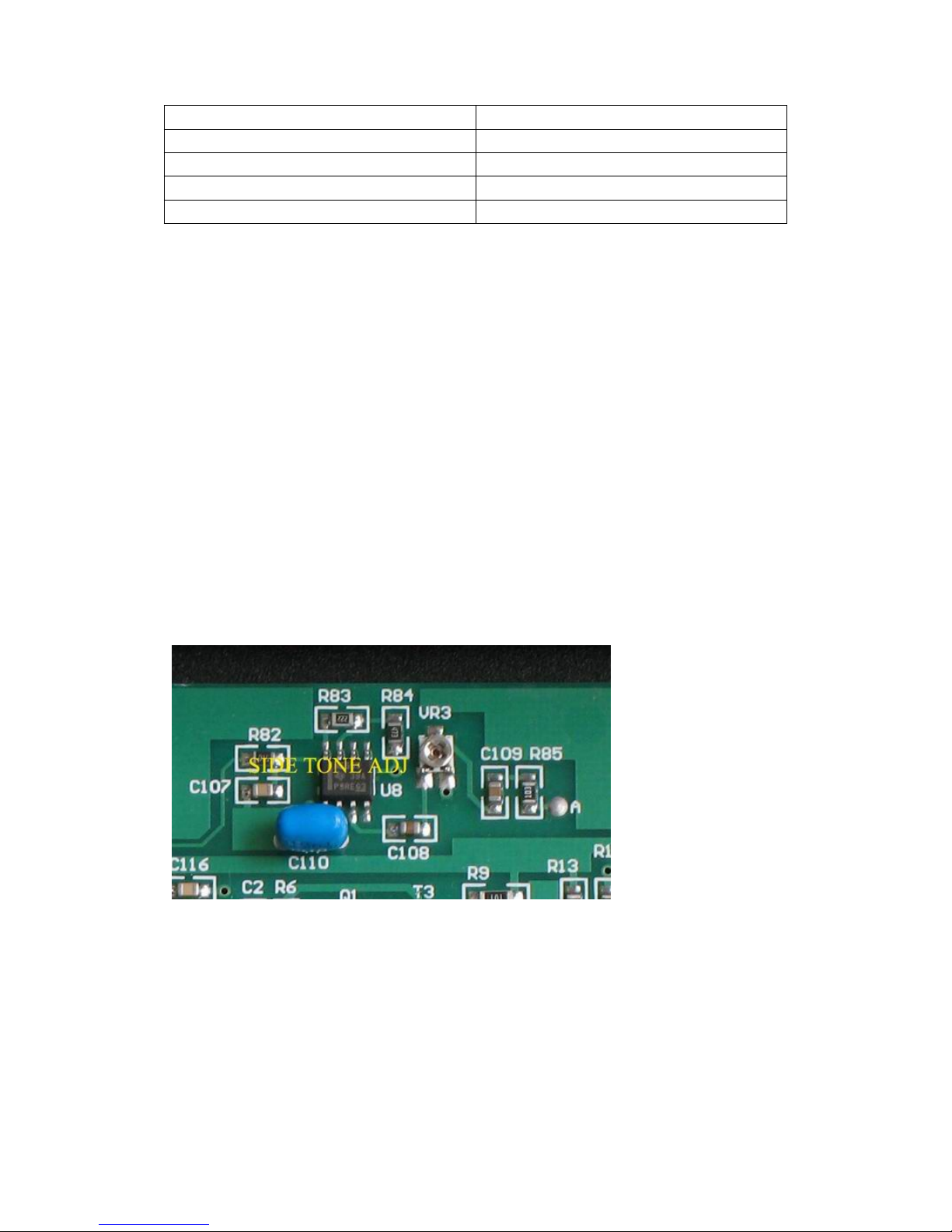
CW operation
In CW mode MIC is disabled. Press the CW key and the CW signal is transmitted. A 950
Hz side tone can be heard from the speaker. The side tone level is not controlled by VOL.
It is pre-set to a certain
level. The level can be
adjusted to meet the
personal desire. If the
level does not suit you,
trim VR3 on the main
board to obtain your
desired level. Open
the upper cover the
TJ5A. Find VR3. Set
the power level to the
lowest. Press KEY and
trim VR3 until the desired side tone level is obtained.
IMPORTANT!
Never try the long key at the full power output. This would overheat the power transistors.
Always use half or lower power to tune the tuner.
Use the matched high efficient antenna such as the dipole, V-dipole, Yagi, long wire with a
tuner. Low efficient antenna, such the small diameter loop, short whip, the shortened wire
of a few meters, etc. are not recommended, which would degrade the sensitivity of TJ5A,
and lower audio output.
11
5. CW Filter
The optional auto-switched-in CW filter is made up of 300 Hz high-pass and 720 Hz
low-pass filters, which greatly improves the selectivity during CW reception. The filter is
switched out in SSB operation.
The filter is fastened on the back of the DDS board by means of a brass stand-off.
Youkits
12/12

Other manuals for TJ5A

3

Other YouKits Transceiver manuals

YouKits HB-1B User manual

YouKits

YouKits HB-1B User manual

YouKits TJ2B Instructions for use

YouKits

YouKits TJ2B Instructions for use

YouKits HB-1B MK3 User manual

YouKits

YouKits HB-1B MK3 User manual

YouKits TJ5A User manual

YouKits

YouKits TJ5A User manual

YouKits TJ5A User manual

YouKits

YouKits TJ5A User manual

YouKits EK-1A Operation instructions

YouKits

YouKits EK-1A Operation instructions

YouKits EK-1B User manual

YouKits

YouKits EK-1B User manual

YouKits HB-1A MK2 User manual

YouKits

YouKits HB-1A MK2 User manual

YouKits TJ5A User manual

YouKits

YouKits TJ5A User manual

YouKits HB-1A MK2 User manual

YouKits

YouKits HB-1A MK2 User manual

YouKits HB-1B MK4 User manual

YouKits

YouKits HB-1B MK4 User manual

YouKits HB-1B User manual

YouKits

YouKits HB-1B User manual

YouKits DIG 40 QRP User manual

YouKits

YouKits DIG 40 QRP User manual

YouKits TJ2B User manual

YouKits

YouKits TJ2B User manual

YouKits EK-1A User manual

YouKits

YouKits EK-1A User manual

Popular Transceiver manuals by other brands

Yaesu FTM-3200DR operating manual

Yaesu

Yaesu FTM-3200DR operating manual

Standard TWIN C568 owner's manual

Standard

Standard TWIN C568 owner's manual

Yaesu FTV-707 instruction manual

Yaesu

Yaesu FTV-707 instruction manual

Yaesu FT-991 operating manual

Yaesu

Yaesu FT-991 operating manual

CTE HP125 VHF user manual

CTE

CTE HP125 VHF user manual

American Fibertek RR-2400 instruction manual

American Fibertek

American Fibertek RR-2400 instruction manual

Kenwood TR-9130 Service manual

Kenwood

Kenwood TR-9130 Service manual

Albrecht AE 560 instruction manual

Albrecht

Albrecht AE 560 instruction manual

EMS EMS520 manual

EMS

EMS EMS520 manual

aci MOD9200LON LONWORKS user manual

aci

aci MOD9200LON LONWORKS user manual

Icom IC-U810T instruction manual

Icom

Icom IC-U810T instruction manual

Icom IC-T7H instruction manual

Icom

Icom IC-T7H instruction manual

CYP COH-TR7 Operation manual

CYP

CYP COH-TR7 Operation manual

Iridium 9523 Product Developer Guide

Iridium

Iridium 9523 Product Developer Guide

Icom iM604A Review guide

Icom

Icom iM604A Review guide

Williams AV Digi-Wave 400 Series quick start guide

Williams AV

Williams AV Digi-Wave 400 Series quick start guide

National Instruments USRP-2950 Getting started guide

National Instruments

National Instruments USRP-2950 Getting started guide

Kirisun PT2508 instruction manual

Kirisun

Kirisun PT2508 instruction manual

manuals.online logo
manuals.online logoBrands
  • About & Mission
  • Contact us
  • Privacy Policy
  • Terms and Conditions

Copyright 2025 Manuals.Online. All Rights Reserved.