Youngman StairMAX 600 User manual

StairMAX
Aluminium Tower
600/700/850 Climbing Rung
3T - Through The Trapdoor Method
User Guide
Edition July 2008
TM

BoSS StairMAX User Guide
1
StairMAX 600
Tower safety
Never overload the tower. The tower’s maximum
working load is 150kg on the platform. Only one
person is allowed on the platform, along with tools
and materials.
Never lean anything against the tower.
Never use if for jobs that excert repetative or
excessive force. Lateral force over 198N -
equivalent to a 20kg weight - make it unstable even
when fitted with stabilisers or balast. This section
includes a table (a) to indicate what level of lateral
force is exerted by typical jobs. Those jobs likley
to exert excessive sideways force should not be
carried out on this tower, whilst those likely to
excert moderate sideways force should be carried
out with due care.
Never use boxes, steps etc to gain extra height.
Never reach too far out to one side.
If the tower is to be repositioned on a higher step,
DO NOT attempt to move it as a complete
assembly. Always dismantle it and rebuild at the
new location.
General Safety
This tower is intended only for indoor use, and must
not be positioned where it could be subjected to
wind loads. Ensure that the site or stairwell where
it is erected does not induce any funneling or
concentrating effect of the wind, or where opening
of doors could introduce sudden wind loads.
Ensure that you are not contravening any health
and safety law (blocking a fire exit for example)
before proceeding to construct the tower on the
stairwell.

youngmangroup.com
2
StairMAX 600
Safety Checklist
Ensure all brace claws operate and lock
correctly prior to errection
Inspect components prior to errection
Inspect tower prior to use
Tower upright and level
Castors locked and legs correctly adjusted
Diagonal braces fitted
Stabilisers/outriggers fitted as specified
Platforms located and windlocks on
Toeboards located
Check guardrails are fitted correctly. See
illustration below.
Ensure horizontal braces and guardrails are fitted
correctly. Always fit as shown.

BoSS StairMAX User Guide
3
StairMAX 600
Component Checklist
Standard Frame (x4)
Gate Frame (x1)
Platform (x1)
Horizontal Brace (x6)
Diagonal Brace (x2)
Stabiliser (x1)
Adjustable Leg (x4)
Base Plate (x4)
End Toeboard (x2)
Side Toeboard (x2)
Tower Dimensions
Maximum safe working height 3.7m
Maximum overall height 3.5m
Maximum platform height 2.3m
Maximum tower length 1.45m
Maximum tower width 0.7m
Complete tower weight (no stabiliser) 52kg
stabiliser 6kg

youngmangroup.com
4
StairMax 600
Assembly Procedure
1
Push base plates onto adjustable leg. Then insert
base plate/adjustabile leg assembly into 2
standard frames. Ensure they are equally they are
equaly extended so that they stand level. These will
now be reffered to as base frames.
2Fit an aditional frame to one of the base frames
and engage the interlock clips. Place the base
frame, fitted with an extra frame, on the lower stair
and the singular base frame on the upper stair,
allowing the correct distance between the frames for
the platform to fit (1.3 metres).

BoSS StairMAX User Guide
5
StairMax 600
Assembly Procedure
3Link these two frames with two horizontal and two
diagonal braces as shown in the illustration, to
form the tower base - start by clipping the horizontal
braces to the frame uprights.
4Fit the platform to the top rungs of the two end
frames. Make sure all four platform end hooks are
in contact with the top rungs, then secure in place by
engaging the hook latches (see illustration). Fit a
standard frame to the top end of the frame that is at
the lower step, secureing it in place with the interlock
clips. Fit the gate frame to the top of the frame that is
resting on the uper step. Make sure that the access
bar is positioned so that it opens in towers the tower.

youngmangroup.com
6
StairMax 600
Assembly Procedure
5Now attach the four guard rails (see illustration)
ensuring that the claws face outward. To
complete the tower, the toeboards must be fitted on
all four sides of the platform.
6Now refer to the stabilisation guide (Page 7) and
table to use the correct means of stabilising the
tower.
The manufacturer strongly recomends that ballast is
used in all applications in addition to any method of
stabilisation used. Please contact your supplier ro
hire shop for details.
If stabiliser(s) are required, they must be fitted to
the corner(s) of the end frame on the lower step,
angled at 45 degrees. The clamps should be fitted to
the clear sections of the frame uprights, away from
the interlock clips and rungs. Once fitted they must
have a minimum sideways extension of 650mm and
also reach down the stairs for a minimum distance
of 650mm. Ensure that the rubber foot is firmly
in contact with the ground, and that the stabiliser
clamps ae securely tightened.

BoSS StairMAX User Guide
7
StairMax 600
Stabilisation guide
Refer to the table below for the correct method(s) of
stabilising the tower for the stairwell in which you intend to
erect it:
Position of tower in
Stairwell
Staircase clear Width
0.8 to
1.4m
1.4 to
2.0m
2.0m or
greater
Free standing (No walls on
either side of staircase) A A A or C
Up against a wall on one
side of the staircase A or D A, B or D A, B or D
Mid-way between walls
on each side of staircase A or D A or D A or C
For additional stability more than one stabilisation method
may be used. The manufacturer strongly recomends
that ballast be used in all applications in addition to the
alternative methods indicated by this guide.
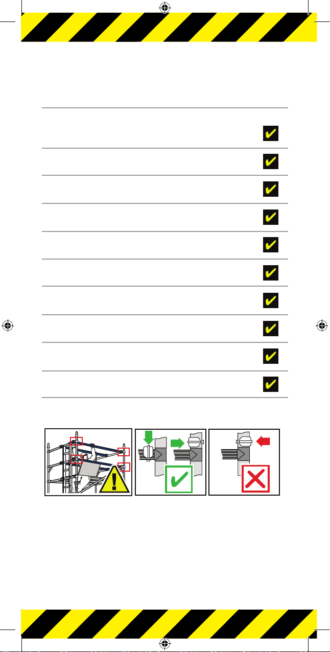
Methods of stabilisation:
AStrongly recomended: The tower is fitted with 150kg of
ballast uniformly spread along the bottom rung of
each base frame (i.e. 75kg at each end). Please contact
your supplier or hire shop for details.
BThe tower is positioned up against a wall on one side,
and a stabiliser is fitted on the other, to the end frame
on the lower step. The stabiliser must have a minimum
sideways extension of 650mm, and reach down the stairs
for a minimum distance of 650mm.
CThe tower is fitted with a stabiliser on both sides, each
with a minimum sideways extension of 650mm, and
reaching down the stairs for a minimum distance of
650mm. Additional stabiliser available from your supplier or
hire shop.
DThe tower is fixed solidly to a wall on one side with ties.
They should be rigid , two-way ties fastened to both
uprights of the frame with load bearing right angled or
swivel couplers. Only couplers suitable for the 50.8mm
diameter tube of the tower should be used. Ideally ties
should secure to either the face of a solid structure or by
means of anchorages. Tying in with rope or non rigid
members is not acceptable.

youngmangroup.com
8
StairMAX 700/850
Mobile Towers - 3t Method
Introduction
Please read this guide carefully.
Please note that diagrams are for illustrative purposes only.
User guides are also available to download from our
website at youngmangroup.com
BoSS Mobile aluminium towers are light-weight scaffold
towers used throughout the building and construction
industry for both indoor and outdoor access solutions
where a stable and secure platform is required. Ideal for
maintenance and installation work or short term access, the
highly versatile towers provide a strong working platform for
a variety of heights.
This user guide provides you with step by step instructions
to ensure your system is erected easily and safely, using the
3T (Through The Trapdoor) method.
The law requires that personnel errecting, dismanatling or
altering towers must be competent. Any person erecting
a Youngman BoSS mobile tower must have a copy of this
guide. For further information on the use of mobile access
and working towers consult the PASMA operators code of
practise.
If you nead further information, design advice, additional
guides or any help with this product, please contact
Youngman on +44 (0)162174 5900 or email sales@
youngmangroup.com
Compliances
The BoSS StairMAX 700/850 aluminium tower system
complies with EN1004:2004 Class 3
Instruction manual EN1298-IM-EN
Preparation and inspection
Inspect the equipment before use to ensure that it is not
damaged and that it functions properly. Damaged or
incorect components shall not be used.

BoSS StairMAX User Guide
9
StairMAX 700/850
Safe Use
Check that all components are on site, undamaged
and that they are functioning correctly - (refer to
checklist and Quantity Schedules). Damged or
incorect components shall not be used.
Check if the ground on which the mobile access
tower is to be erected is capable of supporting the
tower.
For StairMax 700/850 the safe working load is
275kg (606lb) per platform level.
Towers must always be climbing from the inside
using the built in ladder during assembly and use.
It is recomended that towers should be tied to a
solid structure when left unatended.
Adjustable legs should only be used for levelling.
Lifting of equipment
Tower components should be lifted using a reliable
lifting material (e.g. strong rope), employing a
reliable knot (e.g. clove hitch), to ensure safe
fastening and always lift within the footprint of the
tower.
Assembled mobile tower should not be lifted with a
crane or other lifting device.

youngmangroup.com
10
StairMAX 700/850
Stabilisers/Ballast
Stabiliers or outriggers and ballast weights shall
always be fitted when specified.
The Quantity Schedules show the recomended
stabilisation. In circumstances where there
is restricted ground clearnce for stabilisers/
outriggers, contact your supplier for advice. Ballast
must be of solid materials (ie. not water or loose
sand) and should not be positioned to overload
individual legs. Ballast should be secured against
accidental removal where practicable, and should
be supported on the lowest rung of the bottom
frame.
Movement
The StairMAX tower system MUST NOT be moved
once erected. Always dismantle it and rebuild at
the new location.

BoSS StairMAX User Guide
11
StairMAX 700/850
During Use
Beware of high winds in exposed, gusty or medium
breeze conditions. We recomend that in wind speeds
over 7.7 metres per second (17 mph), cease working
on the tower and do not attempt to move it. If the wind
becomes a strong breaze expected to reach 11.3 metres
per second (25mph), tie the tower to a rigid structure. If
the wind is likley to reach gale force, over 18 metres per
second (40mph), the tower should be dismantled.
Wind
Description
Beaufort
Scale
Beaufort
No.
Speed in
m.p.h.
Speed in
m/sec.
Medium
Breeze
Raises dust and loose
paper, twigs snap off.
4 8-12 4-6
Strong
Breeze
Large branches in
motion, telegraph wires
whistle.
6 25-31 11-14
Gale Force Walking is difficult. 8 39-46 17-21
Beware of open ended buildings, which can cause
funneling effect.
Do not abuse equipment. Damaged or incorect
components shall not be used.
Raising and lowering components, tools and or materials
by rope should be conducted within the lower base.
Ensure that the safe working load of the suporting decks
and the tower structure is not exceeded.
The assembled tower is a working platform and should
not be used as a means of access or egress to other
structures.
Beware of horizontal forces (e.g. power tools) which
could generate instability. Maximum horizontal force 20 kg.
Mobile towers are not designed to be suspended -
please refer to your supplier for advice.
Do not use boxes or stepladders or other objects on the
platform to gain extra height.

youngmangroup.com
12
StairMAX 700/850
Ties
Ties should be used when the correct Stabilisation/
Ballast cannot be achieved, or if there is a danger
of instability. They should be rigid, two way ties
fastened to both uprights of the frame with load
bearing right angled or swivel couplers. Only
couplers suitable for the 50.8mm diameter tube of
the tower should be used. Ideally, ties should be
secured to both faces of a solid structure by means
of anchorages.
The tie frequency may vary depending on the
application, but they should, at a minimum, be
every 4 metres height.
For further information on tying-in a tower please
contact your supplier or Youngman.
Maintenance - Storage - Transport
All components and their parts should be regularly
inspected to identify damage, particularly to joints.
Lost or broken parts should be replaced, and any
tubing with indentation greater than 5mm should
not be used and put to one side for manufacture
repair. Adjustable leg threads should be cleaned
and lightly lubricated to keep them free running.
Brace claws, frame interlock clips, trapdoor latches
and platform windlocks should be regularly
checked to ensure they lock correctly.
Refer to the BoSS Inspection Manual for detailed
inspection and maintenance advice.
Components should be stored with dure care to
prevent damage.
Ensure compenents are not damaged by excessive
strapping forces when transported.

BoSS StairMAX User Guide
13
Quantity Schedule
StairMAX 700mm wide x 1.3m & 1.8m 3T build
Component Working height (m) 5.4 6.4
Platform height (m) 3.4 4.4
Base Plate 4 4
Adjusable Leg 4 4
8 Rung Walk Through End Frame 2 2
4 Rung Guardrail Frame
(1.0m high x 0.85m wide) 1 1
7 Rung Span Frame
(1.75m high x 0.85 wide) 2 3
Trap Door Deck 2* 2
Horizontal Brace 5 9
Diagonal Brace 5 6
Side Toeboard 2 2
End Toeboard 2 2
SP7 Stabiliser 2 2
SP10 Stabiliser 2 2
Total Self weight of tower (kg) - 1.3m 111 136
Total Self weight of tower (kg) - 1.8m 120 144
* An additional temporary deck is required as part of
the assembly procedure.

youngmangroup.com
14
Quantity Schedule
StairMAX 850mm wide x 1.3m & 1.8m 3T Build
Component Working height (m) 4.9 5.9
Platform height (m) 2.9 3.9
Base Plate 4 4
Adjusable Leg 4 4
8 Rung Walk Through End Frame 2 2
4 Rung Guardrail frame
(1.0m high x 0.85m wide)
1 1
7 Rung Span Frame
(2.0m high x 0.85 wide)
1 2
Trap Door Deck 2* 2
Horizontal Brace 5 9
Diagonal Brace 6 8
Side Toeboard 2 2
End Toeboard 2 2
Toeboard Holder 4 4
SP7 Stabiliser 2 2
SP10 Stabiliser 2 2
Total Self weight of tower (kg) - 1.3m 100 125
Total Self weight of tower (kg) - 1.8m 109 141
* An additional temporary deck is required as part of
the assembly procedure.

BoSS StairMAX User Guide
15
StairMAX 700/850
Assembly Procedure
The procedure illustrated shows a 700 wide tower with
a platform height of 3.4m.
Youngman recommend two persons are used to build
StairMAX tower and that base plates are used instead
of castors.
1Push 4 base plates
onto adjustable legs.
Insert adjustable leg
assemblies into Walk
through base frame,
as shown. Repeat for
second Walk through
base frame
2Fit a lift frame (1.75m for 700 wide/2.0m for 850
wide) onto the Walk through base frame ensuring
the frame interlock clips are engaged.
Place the two frames onto the stair. This will become
the lower end of the tower.

youngmangroup.com
16
StairMAX 700/850
Assembly Procedure
3Fit one horizontal brace (red) onto the vertical of
the end frame, on the climbing side, above the
5th rung of the portal frame with the claw facing
outwards. The frame will now be self supporting.
Note: All locking claws must be open before tting.
4Position the second
portal frame as
shown, with the openings
on the same side, and fit
the other end of the
horizontal brace just
above the bottom rung.

BoSS StairMAX User Guide
17
StairMAX 700/850
Assembly Procedure
5Fit a pair of diagonal braces between the bottom
rungs of the portal frames, one on each side of
the tower. Fit a diagonal
brace between the 2nd
rung of the higher end
frame and the 10th rung
of the lower end frame.
Ensure the frames are
vertical and level by
checking with a spirit
level and setting the
adjustable legs
accordingly.
6Fit a diagonal brace between the 7th rung of the
lower frame and the 7th rung of the higher frame.
Fit a lift frame (1.75m for 700 wide/2.0m for 850 wide)
onto the Walk though base frame
at the higher end, by
standing higher up the
stairs.

youngmangroup.com
18
StairMAX 700/850
Assembly Procedure
7Fit stabilisers (see notes on page 22). The upper
clamp of the stabiliser must be at least 1.5m above
the bottom of the end frame.
Where possible, the Stabilisers
must also have a minimum
outstand of 1.2m.
8Fit a temporary trapdoor deck on the 7th rung of
the upper frame, as shown. Climb up the inside
of the tower and from the
protected position of the
trapdoor, fit a pair of
horizontal braces as
guardrails on both
sides, to the 9th
rungs counting
at the higher end.
1.5m
Minimum.
1.2m Minimum.

BoSS StairMAX User Guide
19
StairMAX 700/850
Assembly Procedure
9From the protected position of the trapdoor, place
a trapdoor deck on
the 11th rung, counting
at the higher end.
10 Stand on the temporary
deck and, by using
the trapdoor of the higher
deck as a guardrail, fit the
4 rung frame to the lower
end of the tower, Fit a
diagonal brace on one
side of the tower,
between the 8th rung of
the higher end and the
16th rung of the
lower end.
This manual suits for next models
2
Table of contents
Other Youngman Ladder manuals