Tappet Clearance
58
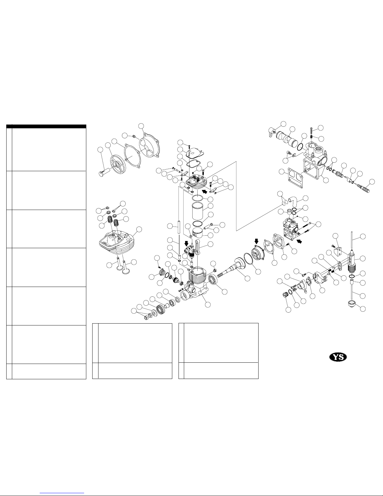
Fuel Filter
High Speed Needle Valve
2563
Regulator
134
111.5
Fuel Tank Clunk
FEATURES
The DZ140 was developed for serious aerobatics competition. The
new design has been in the development stage for more than 3 years. It
differs from previous YS Engines in that it does not use a high pres-
sure fuel system but rather a true fuel pump.
*Crankcase supercharging system unique to YS 4 stroke engines
*Fuel injected
*Convenient fuel pump adjustment
*High horsepower output with long service life
GLOW PLUG
Select the most appropriate glow plug from those designed
specifically for4cycle engines. Glow plug selection greatly affects the
maximum engine output and low idle. If RPM's decrease or stop when
the booster cord is removed, replace the plug. We recommend the
YS#4 or OS Type Fplug for maximum performance.
INSTALLATION
WE RECOMMEND THAT THIS ENGINE BE MOUNTED ON A
SHOCK ABSORBING SOFT MOUNT
1Connect the engine to the tank as shown in fig.1.
The recommended fuel tank size is 500~600cc. You
must use the special clunk supplied with the engine. Please note
that with this clunk,all of the fuel cannot be used from the tank.
As soon as any part of the clunk becomes exposed, the engine
will stop due to air entering the fuel pump.
2Always use a fuel filter. We recommend YS filter.
With this filter, you must remove the cloth portion of the filter and
leave both the metal filter screens in place.
PROPELLER INSTALLATION
Due to the high output power of the 140DZ engine, it is supplied with
a double locknut system for added safety. If you use any other type
of spinner or prop nut device, make sure it is of the double nut type.
1 Mount the propeller and tighten the rear nut. Next, tighten the
front nut as shown in fig.2. The rear nut has an offset shoulder so
the front nut will secure itself to the rear nut.
2Select a good quality propeller that will allow the engine to
run at maximum speed between 7,800 to 9,000 rpm range.
We recommend sizes 15x13 to 17x12. Other prop sizes may be
used as long as the correct rpm range.
START UP
1 Always break the fuel line between the fuel filter and the tank for
filling.This will help to prevent dirt from entering the fuel pump. To
prevent flooding the engine, clamp the fuel line with a hemostat
or clip where it enters the fuel pump.
2 Open the high speed needle 2 turns from the closed position.
The engine should run very rich with the recommended fuel and
glow plug.
3
An electric starter is mandatory for starting this engine.
Attempting to hand start this engine is difficult and dangerous.
4Close the throttle to the idle position and connect the glow driver.
The engine is now ready for starting.
DO NOT ATTEMPT TO START ENGINE AT FULL THROTTLE AS
THIS IS VERY DANGEROUS. ALWAYS USE EXTREME CAUTION
WHEN ENGINE IS RUNNING.
BREAK-IN
To maximize engine performance and increase durability, please follow
this break-in procedure.
1Use the same size ( or slightly smaller ) propeller than you intend
to use in flying.
2Use a good quality fuel containing 15% to 30% nitro, and oil content
of 20% to 24%. Synthetic oil only. If you use caster oil, no more
than 2% is recommended.
DO NOT USE FOUR CYCLE FUEL DUE TO LOW OIL CONTENT.
3 After the engine has started, slowly bring the throttle up to full.
Set high speed needle so it is running at a good rich setting without
the glow driver.
4After the initial 20 minute break-in, mount the engine in the aircraft
and set the high speed to a richer than normal setting for the first
10 flights. This will help to lubricate all moving parts.
HIGH SPEED NEEDLE ADJUSTMENT
1
Adjustment of the high speed is done by the carburetor needle
valve.When the needle valve is turned clockwise, the mixture is
leaner. When it is turned counter-clockwise, the mixture is richer.
A good starting position for the high speed needle valve is 2 turns
open from the fully closed position. At this setting the engine
will be very rich and may die when you remove the glow driver.
If this happens, turn the needle valve in 1/2 turn and try again.
The final running setting for the high speed needle will be
approximately 1 to 1-1/2 turns open from fully closed.
2When the engine is started, open the throttle gradually. Next,
find the peak position ( highest RPM ) by adjusting the needle
valve. Then the needle valve should be opened approximately
1/8 _ 1/4 turns from full RPM to achieve best performance.
REGULATOR ADJUSTING
DO NOT ATTEMPT TOADJUST THE REGULATOR SCREW WITH
THE ENGINE RUNNING. STOPTHE ENGINE BEFORE ADJUSTING
THIS SCREW
The low speed adjustment is the regulator screw on the front of the
engine. Turning the screw clockwise will richen the idle mixture, and
counter-clockwise will lean the idle mixture. It is preset at the factory
but may require further adjustment depending on fuel and conditions
in your areas.
1Wait until the engine is up to operating temperature before
adjusting the idle mixture
2Close the throttle gradually to an idle ( approximately 2,200 rpm ).
Let it idle for 15 -20 seconds and then slowly advance the hrottle.
The adjustment is correct when low to high speed has a smooth
transition.
3If the engine is running rough at idle or too rich, turn the regulator
adjustment counter-clockwise to lean out the low end.
4If the engine speeds up at idle, the low speed mixture is too lean. Turn the
low speed regulator adjustment clockwise to richen the mixture.
TAPPET ADJUSTMENT
Tappet clearance is preset at the factory. Adjustment, if you needed,
should be checked after the initial break-in. For maximum performance,
valves should be checked as normal maintenance.
1Clearance adjustment should be done when the engine is cool.
2Theproper clearance should be set at not more than 0.1mm maximum.
The adjustment is achieved by loosening the lock nut ( fig.3 ) and
turning the adjustment screw. The engine must be at top dead
center on the compression stroke before any adjustments are
made. This engine runs best with the valves set at a tight setting.
If the valves are set too loose ,power will be affected.
CAM GEAR TIMING
If for some reason you have to disassemble your engine, please
follow these important steps on reassembling the cam gear.
1Remove the carburetor and backplate assembly. Notice the
impression mark or dot opposite the rod journal on the crankshaft.
This mark is to point straight down or lined up with the outer case
seam line at the bottom
2 Reinstall the cam with the dot facing you and pointing slightly to
the left. This will allow the cam to turn to the right when properly
installed. The dot should be pointing straight up when cam is fully
installed. Reinstall cam cover and timing is now set.
FUEL PUMP
I
f you must disassemble the fuel pump to change the diaphragm or to
clean, take care that the valves and springs are replaced in exactly the
same manner in which they were removed. Do not disassemble the
pump needlessly. Use care with filtering your fuel and keeping the
entire fuel system in good working order. It will help to prevent fuel
pump problems.
VENTURI RESTRICTOR
DZ140 is equipped with a removable venturi restrictor for increased
fuel economy with only a slight decrease in performance. With the
restrictor in, the RPM drop will be 300 to 400 rpm.
COOLING
In some aircraft installations, cooling of the engine and fuel pump is
extremely critical for optimum performance. Ducting which forces
incoming air around the cylinder head is recommended. Be sure to
provide adequate size inlets and outlets for air traveling through the
cowling.
IMPORTANT
Silicone rubber is used in the YS engines. Only use glow fuel or
methanol forcleaning. Gasolineand other volatilesolvents will damage the
silicone if used. Do not use petroleum based oils as after-run
lubricants.
OPERATOR’S MANUAL
DZ140
SPECIFICATIONS
Bore 32mm
Stroke 29.0mm
Displacement 23cc
Weight 920g
Practical rpm 2,000 -11,000rpm
fig.1
fig.2
fig.3
Front Nut Rear Nut