YT TUES User manual

rtfm.
read first - Then unpack
ZUERST LESEN - DANN AUSPACKEN
D’ABORD LIRE - ENSUITE DEBALLER
BIKE MANUAL

YT-INDUSTRIES.COM
Welcome to good times.

A
B
C
1
2
3
4
5
7
C
B
A
1
2
3
4
5
6
7
8
8
Oberrohr / Toptube / Tube Supérieur
Unterrohr / Downtube / Tube Oblique
Sitzrohr / Seattube / Tube de selle
Kettenstrebe / Chainstay / Base
Sitzstrebe / Seatstay / Hauban
Steuerrohr / Headtube / Tube de direction
Stoßdämpfer / Rear-shock / Amortisseur
Ausfallende / Drop out / Pattes
FEDERGABEL /
SUSPENSION FORK /
FOURCHE
Vorbau / Stem / Potence
Bremshebel / Brake Lever / Levier de frein
Lenker / Handlebar / Cintre
Schalthebel / Shifter / Commande de Vitesses
Steuersatz / Headset / Jeu de direction
Bremse vorne / Front brake / Frein avant
Bremsscheibe / Disc / Disque
LAUFRAD /
WHEEL / ROUE
Schnellspanner-Steckachse /
Quickrelease / Blocage de Roue
Nabe / Hub / Moyeu
Speiche / Spoke / Rayon
Felge / Rim / Jante
Reifen / Tire / Pneu
Ventil / Valve / Valve
Bremse hinten / Rear brake / Frein arrière
Bremsscheibe / Disc / Disque
Zahnkranz / Cassette / Cassette
Kettenführung / Chain Guide / Guide-Chaîne
Kettenblatt / Chainring / Plateau
Schaltwerk / Rear Derailleur / Dérailleur arrière
Kette / Chain / Chaîne
Tretkurbel / Crankset / Pédalier
Pedal / Pedal / Pédale
Sattelstütze / Seatpost / Tige de selle
Sattelstützenklemme / Seatpost Clamp /
Collier de serrage de tige de selle
Gabelkrone / Crown / Té
Standrohr / Stanchions / Plongeur
Tauchrohr / Casting / Fourreaux
Sattel / Saddle / Selle
6
RAHMEN / FRAME / CADRE

MONTAGE WERKZEUG ASSEMBLY TOOLS OUTILS DE MONTAGE
Inbusaufsatz Größe 4, 5 und 6mm
Inbusschlüssel Größe 4, 5 und 6mm
Drehmomentschlüssel mit 17er Nussaufsatz
Seitenschneider
Dämpferpumpe (Modelle mit Luftfeder)
Reifenpumpe
Montagefett
Carbon-Montagepaste
Torque wrench with Allen key adapter size 4, 5 and 6
Allen key size 4, 5 and 6
Torque wrench with socket key 17 mm
Wire cutter
Shock pump (models with air suspension)
Tire pump
Assembly grease
Carbon Paste
Clé dynamométrique avec insert Clé Allen, taille 4, 5 et 6
Clé Allen, taille 4, 5 et 6
Clé dynamométrique avec douille 17 mm
Pince coupante
Pompe amortisseur (modèles avec amortisseur à air)
Pompe de gonfl age des pneus
Graisse de montage
Graisse spéciale carbone
FEDERGABEL /
SUSPENSION FORK /
FOURCHE

INTRODUCTION
Congratulations on your new bike and
thanks for choosing YT INDUSTRIES.
PLEASE NOTE:
A mountain bike is a piece of technical sports equipment that in order to
function properly and sustainably satisfy the user demands a certain level of
technical know-how as well as assembly and maintenance skills.
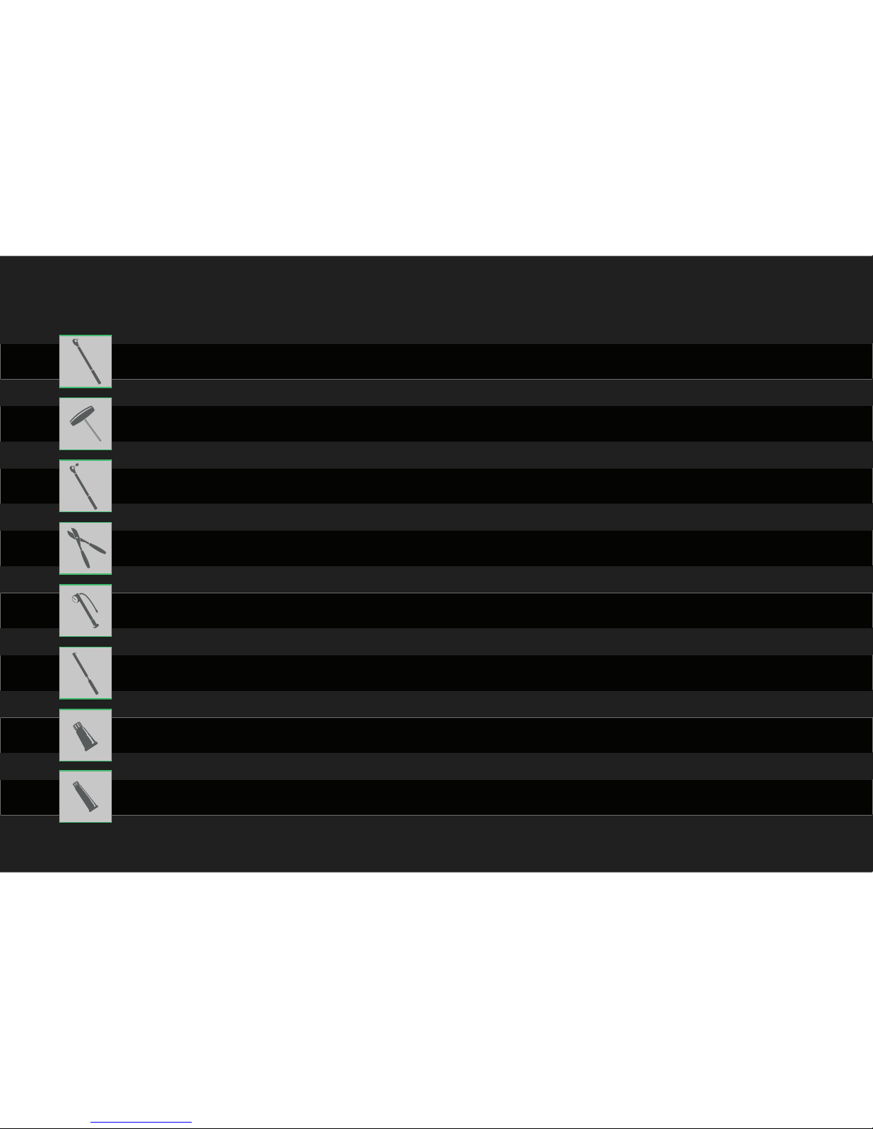
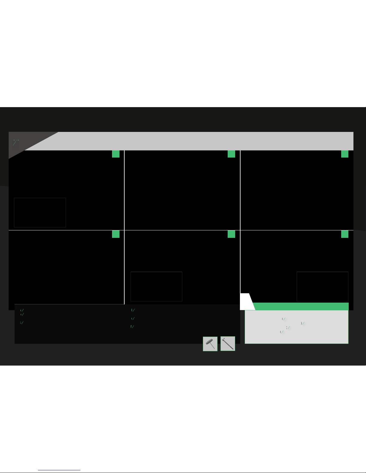
Furthermore we assume that the users of our bikes possess suitable tools in
order to execute the necessary assembly steps without damaging the parts.
These assembly instructions cannot replace professional instruction or training
as bike mechanic.This manual is not intended to provide the knowledge
nor the skills required for professionally assembling a piece of
high tech sports equipment, like a mountain bike,
from single parts or for repairing such equipment.
Please understand that in case of self-executed repairs and/or
on-professional maintenance warranty on components shall be void
and we shall not accept liability for consequential accidents or damages.
TIP:
Please save the YTIndustries BikeBox including the
packaging material.This way, you can repack your
bike if you need to have it transported.
ATTENTION:
If you don’t feel confi dent in your abilities to perform the necessary
maintenance and repairs appropriately, seek out a bike shop!
Of course, you can always contact us if you have any queries.
But exclusion from warranty and limitations of our liability apply in
this case, too. When dealing with inquires by phone or mail,
we cannot ensure that the extent and the nature of the problems and
the applicable remedies have been described correctly and completely
and therefore we cannot control whether our work instructions have
been implemented correctly and to the full extent.
ASSEMBLY INSTRUCTIONS
eng

ASSEMBLY INSTRUCTIONS
UNPACKING THE FRAMEUNPACKING THE WHEELSOPENING THE BOX STEP
STEP
03
STEP
STEP
02
STEP
STEP
01
a
a
Cut the straps using wire cutters or a box cutter.
Just make sure that you do not damage the BikeBox.
b
b
Now you can pull out the fl aps and open the BikeBox.
a
a
Lift the wheels upwards out of the box.
b
b
b
Place the wheels in a safe place on their side.
a
a
Now you can pull your bike upwards out of the BikeBox.
b
b
b
Place the frame on the front/rear axle stand.
Make sure the bike is standing properly!
a a a
b b b

STEP
STEP
04 A INSTALLING THE HANDLEBAR - RACE FACE ATLAS DIRECT MOUNT
a
a
Remove the screws of the stem from the upper fork crown (5 mm Allen wrench).
b
b
b
Place the handlebar and stem on the fork crown.
c
c
c
Install the stem on the fork crown (5 mm Allen wrench).
d
d
Tighten the screws gradually with only one turn per screw in an X pattern.
This is the only way to achieve even clamping of the handlebar in the stem.
e
e
Adhere to the guidelines of the manufacturer of the stem and/or handlebar when
torqueing the screws. Make sure that the clamp gap is even and that the handlebar is
centered and inserted correctly. The adjustment lines will help you with this.
Adjust the handlebar to your preferred position by using a 5 mm Allen wrench.
a c e
b d
eng
During assembly, please adhere to the torque specifi cations of the manufacturers:
RaceFace Atlas Direct Mount
9Nm
Renthal Integra II: Fork crown screws (large)
10Nm;
Handlebar clamp screws (small)
6Nm
YT Industries Direct Mount
5Nm
(Last updated 2015)
CAUTION!
!

STEP
STEP
04 B INSTALLING THE HANDLEBAR - RENTHAL INTEGRA II
a c e
fb d
During assembly, please adhere to the torque specifi cations of the manufacturers:
RaceFace Atlas Direct Mount
9Nm
Renthal Integra II: Fork crown screws (large)
10Nm;
Handlebar clamp screws (small)
6Nm
YT Industries Direct Mount
5Nm
(Last updated 2015)
CAUTION!
!
a
a
Remove the screws of the stem from the upper fork bridge (5 mm Allen wrench).
b
Remove the screws of the stem from the upper fork bridge (5 mm Allen wrench).
b
b
Install the 2 lower bolts of the stem, but do not tighten them at this point.
Remove the bolts holding the top clamps in place.
c
Remove the bolts holding the top clamps in place.
c
Slide the clamps sideways over the handlebar into the mounting position.
Attach the handlebar and the top clamps to the base of the stem
(on the top crown of the fork).
d
d
Start to tighten the four crown screws fi rst.
Make sure there is no gap between the baseplate and the clamp.
e
Make sure there is no gap between the baseplate and the clamp.
e
Tighten the two front screws and make sure the handlebar is centered
and inserted correctly.The adjustment lines will help you with this.
f
and inserted correctly.The adjustment lines will help you with this.
f
Respect the torque recommendations of the manufacturer of the handlebar and stem.
ASSEMBLY INSTRUCTIONS

STEP
STEP
04 C INSTALLING THE HANDLEBAR - YT INDUSTRIES DIRECT MOUNT
a c e
fb d
a
a
Remove the screws of the stem from the upper fork crown (6 mm Allen wrench).
Install the stem on the fork bridge (6 mm Allen wrench).
b
b
Tighten the screws gradually with only one turn per screw in an X pattern.
This is the only way to achieve even clamping of the handlebar in the stem.
c
c
Remove the screws from the clamp of the stem.
d
d
Install the handlebar in the stem.
e
e
e
Tighten the screws gradually with only one turn per screw in an X pattern.
This is the only way to achieve even clamping of the handlebar in the stem.
f
f
Adhere to the guidelines of the manufacturer of the stem and/or handlebar when
torqueing the screws. Make sure that the clamp gap is even and that the handlebar is
centered and inserted correctly. The adjustment lines will help you with this.
During assembly, please adhere to the torque specifi cations of the manufacturers:
RaceFace Atlas Direct Mount
9Nm
Renthal Integra II: Fork crown screws (large)
10Nm;
Handlebar clamp screws (small)
6Nm
YT Industries Direct Mount
5Nm
(Last updated 2015)
CAUTION!
!
eng

REMOVE WHEELS
FROM PACKAGING INSTALLING THE REAR DERAILLEUR
a
a
b
b
Cut the cable ties using wire cutters and
remove the cardboard packaging.
a a c
b b
a
a
Open the rear derailleur cage by holding the derailleur body with one hand,
and turning the cage forward with your other hand.
b
b
The rear derailleur cage is locked by pressing and holding the small button
with the lock symbol.The rear derailleur will then stay open.
c
c
Mount the derailleur using the Torx T25 (7-speed) or
5 mm Allen wrench (10-speed) on the derailleur hanger.
Please make sure the bolt is perpendicular to the hanger to avoid
damaging the thread.
ASSEMBLY INSTRUCTIONS
STEP
STEP
06
STEP
STEP
05
During assembly, please adhere to the torque specifi cations of the manufacturers: 8 - 10 Nm
CAUTION:
!

INSERTING THE REAR WHEEL & ASSEMBLY STAND INSTRUCTIONS
a
a
Lift the frame out of the rear stand.
Place the rear stand upright...
… so that you can place the frame on it again as pictured
(this way,the rear wheel can be inserted into the rear dropouts
without having to turn the bicycle upside down).
b
without having to turn the bicycle upside down).
b
c
without having to turn the bicycle upside down).
c
Remove the safety bolt with a 5mm Allen key, followed by
the axle itself with an 8mm Allen, then remove the transportation spacer.
c
c
Pull the brake protector from the brake cylinder straight downwards. Please store this
in a secure location. It keep the brakes from engaging when transporting the bike by car.
d
in a secure location. It keep the brakes from engaging when transporting the bike by car.
d
Place the rear wheel into the frame and place the chain on the smallest cog
(use the shifter to shift into the smallest gear fi rst). Check that the rear wheel is inserted
correctly and that the brake rotor is inserted between the brake pads.
If everything is inserted correctly, the rear axle can be reinserted.
e
e
Tighten the rear axle using a torque wrench (15 Nm).
Now insert the locking screw and tighten to 6 Nm.
f
Now insert the locking screw and tighten to 6 Nm.
f
Now you can release the rear derailleur locking mechanism by turning the cage forward.
a c e
b d f
STEP
STEP
07
eng

INTERMEDIATE STATE
If your bike looks like the image, then you have done everything correctly so far.
Well done!
a
a
Remove the front axle stand
and turn the bike upside down.
a
ASSEMBLY INSTRUCTIONS
STEP
STEP
08 STEP
STEP
09A

b d f
g
e
c
INSERTING THE FRONT WHEEL - ROCKSHOX BOXXER
b
b
Loosen the screw on the brake side using a 6 mm Allen wrench until you no
longer hear a clicking sound. Remove the axle using a 6 mmAllen wrench on
the side with the rebound adjuster knob.
c
c
Remove the pad spacer from the front brake caliper by pulling it straight outwards.
Store the spacer in a secure location as it can be used to prevent the brakes engaging
and pushing the brake pads out when transporting the bike without its wheels.
d
d
Now insert the front wheel in the fork dropouts.
Ensure that the hub is sitting correctly in the dropouts,
and that the brake rotor is positioned between the brake pads.
e
e
Now the front axle can be inserted.
f
f
Slide the lightly greased axle through the hub until the thread
engages the opposite dropout and tighten the axle
to 5-6 Nm using a 6 mm Allen wrench.
g
g
Tighten the safety screw on the opposite side by turning it
until you hear 8 distinct clicks.
eng

bdf
a c e
INSERTING THE FRONT WHEEL - BOS IDYLLE
a
a
Loosen the four securing screws using a 4 mm Allen wrench.
b
b
b
Remove the axle using a 6 mm Allen wrench.
c
c
Remove the pad spacer from the front brake caliper.Store the spacer in a
secure location as it can be used to prevent the brakes engaging and pushing
the brake pads out when transporting the bike without its wheels.
d
d
Now insert the front wheel in the fork dropouts.
Ensure that the hub is sitting correctly in the dropouts,
and that the brake rotor is positioned between the brake pads.
e
e
Ensure that the brake rotor sits correctly between the brake pads.
Now the front axle can be inserted.
f
f
Slide the lightly greased axle through the hub until the thread engages
the opposite dropout and tighten it by hand using a 6 mm Allen wrench.
ASSEMBLY INSTRUCTIONS

g
g
Tighten the securing screws on the brake rotor side alternately with only one
turn per screw.This is the only way to achieve even clamping (tighten each screw
to 3 Nm using a 4 mm Allen wrench).
Before tightening the securing screws on the other side, press down on the fork
once and let it rebound and install the screws just as you did before:
Tighten them alternately to 3 Nm using a 4 mm Allen wrench.
INSTALLING PEDALS
a c
b
a
a
Place the pedal washer on the pedal axle.
b
b
b
Apply suffi cient grease to the pedal thread.
Excess grease can be wiped away after the pedals have been installed.
c
c
Install the pedals using an Allen wrench (the size will vary by pedal manufacturer).The
drive side pedal has standard threading and the non-drive side pedal has reverse thread-
ing.Therefore, the non-drive side pedal is tightened by screwing it in counterclockwise.
Tighten the pedals using the torque wrench.
Please note the torque specifi cations of the manufacturer here as well.
STEP
STEP
10
g
eng

You’re fi nished! Congratulations! You’re bike is now fully assembled.
Please note the following information for adjusting your bike.
FULLY ASSEMBLED BIKE
STEP
STEP
11
ASSEMBLY INSTRUCTIONS

ADJUSTING THE SUSPENSION ELEMENTS
(REAR SHOCK AND SUSPENSION FORK)
The suspension elements that we use allow for a variety of adjustments.
When making adjustments, please note the detailed instructions of the
manufacturer of the suspension elements.
You can fi nd up-to-date information on their websites, respectively:
BOS: http://www.bosmtb.com
RockShox: https://www.sram.com/de/rockshox
CAUTION!! NEVER OPERATE YOUR BICYCLE WITH INSUFFICIENT OR EXCESS
AIR PRESSURE! THIS COULD RESULT IN DAMAGE TO THE FORK OR SHOCKS.
BASIC SETTINGS
The weight of the rider and his position on the bicycle determine the adjustment criteria for
the rear shock and suspension fork. When sitting on the bike, the suspension will compress
to a certain degree – the so-called “sag.” Sag should be between 25% and 30% for Enduro
bikes, between 30% and 40% for Downhill bikes, and between 10% and 20% for Dirt bikes.
The “sag value” that corresponds to your riding style is best determined with a few test rides.
Test rides and personal preferences will determine the settings of the compression and
rebound speeds of the suspension elements.
CAUTION!! Please note:
Your bike’s handling is infl uenced with each and every adjustment to the suspension
elements – therefore, please be careful on your fi rst test rides to avoid falls and crashes.
Avoid any adjustments that could lead to the suspension elements frequently bottoming
out. They will thank you with a long service life. If you are uncertain of anything or have any
questions, do not hesitate to contact us at: [email protected]
GET TO KNOW YOUR BIKE
Familiarize yourself with your new bike. Verify once again that all screws are tightened to
the correct torque. The table on page 31 gives you an overview of all torque specifi cations.
Our bikes are equipped with modern disc brake systems with exceptional braking
performance. In addition, the braking performance increases after a short break-in period.
Try to get used to the braking response and how it differs when riding over various surfaces.
Position the brake levers at your fi ngertips so that they can be pulled forcefully without
excessive effort. The same applies to the shifters. Shift smoothly and without applying too
much pressure to the pedals.This will help protect your drive train components.
Please choose a safe and familiar terrain for your initial test and training rides.
You can fi nd all you need to know about your bike in our “SAFETY FIRST” manual as well.
Familiarize yourself with the bike manual before getting on your bike the fi rst time.
BEFORE EACH RIDE
By nature, mountain bikes are placed under a lot of strain. The components
of the bike react differently to stresses, from wear and tear to material fatigue.
Individual components may fail without warning. Please check your bike regularly
for signs of damage and/or have your bike periodically inspected.
CHECK BEFORE EVERY RIDE:
- that the seatpost and wheels are fi rmly secured in the frame and fork
- that the wheels spin freely
- the air pressure in the tires, the tension of the spokes and the hub bearing play
- the brake function
- signs of material fatigue (deformations, fractures, cracks, signs of impact, etc.)
- all additional components for stability and operational safety
- the required torques for all screws
Do not ride even if only one of the possible defects is present.
CAUTION!! Vibrations that occur when riding your mountain bike can lead
to screws loosening (even for screws with threadlocker adhesive)!
IN THE EVENT OF A FALL
Falls place a lot of strain on your bike’s material and components.
Therefore, before you continue on your ride, check your bike for damage
and impaired functions (see “Check Before Every Ride”).
Do not continue your ride even if only one of the possible defects is present.
If you are uncertain of anything or have any questions, do not hesitate
to contact us directly at: [email protected]
RIDING ON PUBLIC ROADS IN GERMANY
The German Road Traffi c Licensing Regulations (Straßenverkehrs-Zulassungs-Ordnung,
StVZO) prescribes the following safety devices when operating bicycles on public roads:
- A braking and lighting system and a bright sounding bell.
- Furthermore, every cyclist is obligated to maintain his vehicle in a roadworthy
condition and a state that safe for riding.
We would like to expressly point out that our bikes are not in compliance with
the German road traffi c licensing regulations! Read more about this
on pages 75 - 78 in the “SAFETY FIRST” manual.
RIDING ON PUBLIC ROADS OUTSIDE OF GERMANY
Please inquire about the respective regulations in place for the country in which
you want to ride your YT Bike in “normal” traffi c.
DESIGNATED USE
In addition to the assembly instructions, our mountain bikes are also supplied with
the operating instructions from the manufacturers of the individual components.
You can fi nd all information regarding use, maintenance, and care here.
Please follow these instructions and retain them.Damage that arises from improper
or inappropriate use are not covered by our warranty.
These include:
- Improper or inadequate maintenance and care
- Damage from falling or overstressing
- Modifi cation to the frame or fork
- Modifi cation of components
- Jumps or other stresses that lead to overstraining
- Operating the bike with a total weight of over 120 kg / 265 lbs.
Please refer to our General Terms and Conditions at www.yt-industries.com.
IMPORTANT GENERAL INFORMATION:
We are not liable for property damage or personal injury resulting from the operation of
the mountain bike itself, in particular, in the event of failures due to inadequate
maintenance and care.
The abilities of professional mountain bikers may seem easy to imitate to laypersons.
In reality, there are often years of training and constant practice behind their skills.
For your safety, always wear protective clothing commensurate with the discipline.
We recommend always wearing a protective helmet.
Things always seem to happen when you least expect them.
CARE AND SERVICE INTERVALS:
Only regular inspections, care and maintenance,immediate professional repair,and the
replacement of damaged components can guarantee the safe function of your bike over
the long term. If you do not possess the necessary specialist knowledge or tools to
carry out the required work yourself, a trip to the workshop is essential.
For guidance, we have prepared some maintenance information:
Initial inspection, depending on how hard you ride,after 5 to 15 hours of operation.
This includes:
- Checking the torques on all screws and nuts and tightening them if necessary
- Changing the length of the shifter cable by correcting the tension via adjustment
(barrel adjuster on the shifter)
- Checking the spoke tension on the wheels and that the wheels are true and
adjusting spoke tension if necessary
- Checking the headset preload
MONTHLY INSPECTIONS:
- Checking the profi le height and sidewalls of the tires.
Replacing worn or “washed out” tires
- Measuring the strength of the disc brake pads.
Replacing the brake pads if necessary (please note the manufacturer specifi cations)
- Checking the braking system for leaks. In the event of leaks, please visit a workshop
- Checking bearing play in the bottom bracket, headset, hubs, and pedals
and tightening if necessary
- Checking the spoke tension on the wheels and that the wheels are true
and adjusting spoke tension if necessary
- Checking the torques on screws and nuts. If necessary, tightening screws and nuts
- Cleaning and greasing the drivetrain and derailleur mechanism
ANNUAL INSPECTION:
- Suspension fork service: Please note the specifi cations of the manufacturer here
- Remove the bottom bracket, clean it, and regrease the treads
- Remove the headset, check the bearings and regrease them
- Remove the stem, handlebar, and seatpost and check them for cracks and damage
and replace them if necessary
- Check the shifter cable for damage (breaks, kinks, corrosion, etc.)
and exchange them if necessary
Adjustments after assembly
YOU CAN FIND DETAILED INFORMATION ABOUTYOUR BIKE IN THE “SAFETY FIRST” BICYCLE MANUAL.
eng

ENG
INFORMATION ON THE HANDLING AND USE OF BIKE FRAMES MADE FROM CARBON (CFRP)
TO AVOID DAMAGE TO PERSONS AND PROPERTY WE ASK YOU
TO FOLLOW THESE INSTRUCTIONS.
The use of carbon (carbon fi ber reinforced plastic / CFRP) makes it possible for us to produce
high-performance products for our customers. Since these components and frame elements
can be sensitive and delicate under certain conditions, there is a risk of breaks which could
lead to accidents and property damage in the event of improper use, assembly errors or
poor maintenance and care. That is why being knowledgeable about this material is
important for enjoying a carbon frame in the long term.
When these products are overstressed, no lasting deformations are visible even though the
inner structure could be damaged. In addition, rock impacts or messy falls involving impacts
on edges can result in invisible damages and/or delamination (= carbon layers dissolve)
of the carbon material.
For these reasons, an element or frame made of CFRP can fail without perceptible warning..
CONTACTYT INDUSTRIES IMMEDIATELY AFTER YOU HAVE A FALL!
Pay attention if your carbon frame makes unusual snapping noises. This could be a sign of
an impending material defect. If this occurs, stop using the bike immediately.
IF THE FOLLOWING OCCURS, IT IS ABSOLUTELY ESSENTIAL TO HAVE THE
FRAME INSPECTED BY YT INDUSTRIES:
After a fall
Other major mechanical stresses
Unusual noises from the frame (e.g. snapping sounds)
INFORMATION ON FRAME CONSTRUCTION
The manufacture of these high-end products is done by hand.
This can lead to differences in the fi nish which are not cause for complaint.
HOW TO CORRECTLY HANDLE YOUR CARBON FRAME:
General information:
Under no circumstances should you install rings, screw connections,
clamps or other elements which exert mechanical forces on the carbon tube.
Never clamp the carbon tube or carbon seat post of your bike on the gripping
jaws of a work stand or bike rack.
Be careful when using U-locks – under certain circumstances,
they can cause damage to your frame.
Seat cable clamp / seat post:
The prescribed tightening torque of the seat cable clamp bolt is 5 Nm.
The seat post must not be rubbed or otherwise mechanically stressed.
The seat post and seat tube may not be lubricated.
Only carbon assembly paste can be used.
Aluminum seat posts may only be installed when carbon assembly paste is used.
The seat clamp must not be closed when the seat post has been removed.
Carbon Handlebar:
Installing carbon handlebars requires great care and precision. Do not exceed the
specifi ed torque under any circumstances and make sure that the stem does not have
any sharp edges or ridges.
Please note the prescribed tightening torque of the stem manufacturer.
Carbon handlebars can only be installed using carbon assembly paste.
If you would like to shorten the handlebar, note the specifi cations of the manufacturer
or contact us directly.
Rear wheel axle:
To prevent damages to the seat stays, the rear wheel axle must never be completely
closed if the wheel is not in the frame.
Transport:
You must be particularly careful when transporting bikes with carbon frames:
Protect the frame in particular from contact with other parts (use covers, etc.).
Do not use transport fi ttings which use clamping elements.
Clamping forces could damage the frame structure.
Do not place any objects on the frame.
Make sure the bike cannot slide around during transport.
Never transport without rear wheel or rear section transport lock assembled.
CARE INFORMATION:
Your carbon frame needs regular care. Common paint care products with or without silicon
additives and cold to lukewarm water are suitable for cleaning.
You can add common cleaners with normal additives to the cold to lukewarm water.
All solvents must be avoided:
Alcohols (e.g. ethanol or isopropanol)
Hot water with alkaline additives
Do not clean with steam jets or high-pressure cleaners
Check whether your frame has external damage at regular intervals
(e.g. during maintenance):
Cracks
Paint damages
Deformation (bulges, etc.)
Discoloration
SURFACE PROTECTION:
YT Industries carbon frames are equipped with protective foils or protectors made of
polyamide or polyurethane at points which are exposed to particular stress.
Other points could form due to different application areas and conditions (e.g.wearing
knee protectors). These areas must be protected against damage or abrasions with
additional protective foils.
Please check at regular intervals whether the protective foils are still functional.
We recommend replacing the protective foil around tension points once a year.
IF NO WHEEL INSTALLED KEEP REAR WHEEL AXLE LOOSE! USE TRANSPORT LOCK!! CHECK PROTECTIVE FOILS REGULARLY!

Bottom bracket
Brake caliper screw to frame and fork
Shifter
Disc brake bolts to hub
Rear derailleur (fi xing bolt)
Rear derailleur (clamp bolt)
Brake lever
Cassette retainer ring
Handlebar Clamp
Stem (steerer tube clamping)
Crank bolts
Chain ring bolts
Pedals
Lock-on grip bolts
33 - 41 Nm
9,5 Nm
2,5 - 4 Nm
6 Nm
8 - 10 Nm
4 - 5 Nm
2,8 - 3,4 Nm
40 Nm
6 Nm (Carbon / Aluminium)
9,5 Nm
48 - 54 Nm
12 - 14 Nm (Steel)
8 - 9 Nm (Alu)
38 Nm
2,5 - 4 Nm
TORQUE CHART
eng
CAUTION!
These specifi cations are only guidelines.
As a rule, you should always observe the manufacturers’ instructions.
These have also been included or can be found on the website
of the respective manufacturer.

ZWEIBRÜCKENSTRASSE 2
91301 FORCHHEIM
91301 FORCHHEIM
GERMANY
GERMANY
YT INDUSTRIES
GmbH
+49 (0) 9191 . 73 63 05 0
+49 (0) 9191 . 73 63 05 0
+49 (0) 9191 . 73 63 05 55
+49 (0) 9191 . 73 63 05 55
service@yt-industries.com
yt-industries.com
yt-industries.com
yt-industries.com
PHONE
FAX
MAIL
WEB
Table of contents
Other YT Bicycle manuals