YUGE LPM2100 bg Series Parts list manual

Product name
LPM2100 bt NB Module Hardware Usage Guide
Number of pages
40
Hardware design version
V1.1
Document version
V1.2
Date
2019/5/10
LPM2100 bt NB Module
Hardware Usage Guide
V1.2
Shanghai Yuge Information Technology Co., Ltd.

LPM2100 bt NB Module Hardware Usage Guide
Shanghai Yuge Information Technology Co., Ltd.
- 2 -
update record
Version
Date
Author
Description
V1.1
2019/3/21
John.zhang
Fix and add some configuration information
V1.1
2019/5/10
John.zhang
Modify some information about hardware V1.1
interface changes
V1.2
2019/6/3
John.zhang
Modify information for hardware V1.1 format

LPM2100 bt NB Module Hardware Usage Guide
Shanghai Yuge Information Technology Co., Ltd.
- 3 -
Contents
Chapter 1. Introduction...........................................................................................................- 7 -
Chapter2. Module review....................................................................................................... - 8 -
2.1 Module introduction................................................................................................. - 8 -
2.2 Main performance.................................................................................................... - 9 -
2.3 Module functional block diagram...........................................................................- 11 -
2.4 Module working mode............................................................................................- 11 -
Chapter 3. Interface application description.........................................................................- 13 -
3.1 Chapter overview....................................................................................................- 13 -
3.2 Module interface.....................................................................................................- 13 -
3.2.1 LPM2100 bt Pin map............................................................................ - 13 -
3.2.2. Module pin description...............................................................................- 14 -
3.3 Power interface.......................................................................................................- 18 -
3.4 VDD_EXT Voltage output.................................................................................. - 19 -
3.5 Switching machine reset mode...............................................................................- 19 -
3.5.1 Boot............................................................................................................. - 19 -
3.5.2 Boot timing..................................................................................................- 19 -
3.5.3 Module shutdown........................................................................................ - 20 -
3.5.3 Reset control................................................................................................- 20 -
3.6 UART interface...................................................................................................... - 22 -
3.6.1 Serial application circuit..............................................................................- 23 -
3.7 Power saving technology........................................................................................- 24 -
3.7.1 Power Saving Technology (PSM)............................................................... - 24 -
3.7.2 Power Saving Technology (DRX)...............................................................- 25 -
3.7.3 Power saving technology (eDRX)...............................................................- 25 -
3.7.4 WAKEUP interface...................................................................................- 26 -
3.7.5 WAKEUP_OUT interface........................................................................ - 26 -
3.8 SIM interface.......................................................................................................... - 27 -
3.8.1 SIM card reference circuit........................................................................... - 27 -
3.8.2 SIM_DECT Hot swap reference design *................................................... - 28 -
3.9 ADC interface.........................................................................................................- 29 -
3.10 SPI interface......................................................................................................... - 30 -
3.11 I2C bus..................................................................................................................- 30 -
3.12 Network indication interface................................................................................ - 31 -

LPM2100 bt NB Module Hardware Usage Guide
Shanghai Yuge Information Technology Co., Ltd.
- 4 -
3.13 General purpose GPIO interface.......................................................................... - 32 -
Chapter 4. Overall RF technical indicators.......................................................................... - 33 -
4.1 Chapter overview....................................................................................................- 33 -
4.2 Main antenna.......................................................................................................... - 33 -
4.3 GNSS antenna........................................................................................................ - 34 -
4.4 RF signal line routing guide................................................................................... - 35 -
4.5 RF connector.......................................................................................................... - 36 -
4.6 Working frequency and module series................................................................... - 37 -
4.7 Conducted transmit power and receive sensitivity.................................................- 37 -
4.8 Power consumption characteristics........................................................................ - 38 -
Chapter 5. Interface electrical characteristics.......................................................................- 39 -
5.1 Chapter overview....................................................................................................- 39 -
5.2 Range of working temperature............................................................................... - 39 -
5.3 Module IO level......................................................................................................- 39 -
5.4 Power supply.......................................................................................................... - 39 -
5.5 Electrostatic property..............................................................................................- 40 -
5.6 Reliability index..................................................................................................... - 40 -
Chapter 6. Structural and mechanical properties..................................................................- 42 -
6.1 Chapter overview....................................................................................................- 42 -
6.2 Exterior................................................................................................................... - 42 -
Chapter 7. Production and packaging...................................................................................- 45 -
7.1 Chapter overview....................................................................................................- 45 -
7.2 Module packaging and storage...............................................................................- 45 -
7.3 Production welding.................................................................................................- 45 -
Chapter 8. Abbreviation........................................................................................................- 47 -

LPM2100 bt NB Module Hardware Usage Guide
Shanghai Yuge Information Technology Co., Ltd.
- 5 -
Figure
Figure 2-1 Functional block diagram of the LPM2100 bt series module.............................- 11 -
Figure 3-1 LPM2100 bt pin assignment diagram.................................................................- 14 -
Figure 3-2 VBAT power supply........................................................................................... - 18 -
Figure 3-3 VDD_EXT power output timing diagram.......................................................... - 19 -
Figure 3-4 boot timing diagram............................................................................................- 19 -
Figure 3-5 Shutdown timing diagram...................................................................................- 20 -
Figure 3-6 Reset reference circuit........................................................................................ - 21 -
Figure 3-7 Reset timing diagram..........................................................................................- 21 -
Figure 3-8 Full-featured serial port design...........................................................................- 23 -
Figure 3-9 UART serial port design..................................................................................... - 23 -
Figure 3-10 UART level conversion circuit......................................................................... - 24 -
Figure 3-11 PSM power saving technology......................................................................... - 25 -
Figure 3-12 DRX power saving technology.........................................................................- 25 -
Figure 3-13 eDRX power saving technology.......................................................................- 25 -
Figure 3-14 WAKEUP wake-up module reference circuit................................................... - 26 -
Figure 3-15 WAKEUP_OUT wake-up host reference circuit.............................................. - 26 -
Figure 3-16 SIM circuit design.............................................................................................- 28 -
Figure 3-17 SIM card hot swap detection circuit*............................................................... - 29 -
Figure 3-18 SPI read timing diagram................................................................................... - 30 -
Figure 3-19 SPI write timing diagram..................................................................................- 30 -
Figure 3-20 I2C interface reference circuit.......................................................................... - 31 -
Figure 3-21 Network indicator circuit diagram....................................................................- 32 -
Figure 4-1 Main antenna matching circuit diagram............................................................. - 33 -
Figure 4-2 GNSS antenna matching circuit diagram........................................................... - 35 -
Figure 4-3 Complete structure of the microstrip line........................................................... - 35 -
Figure 4-4 Reference ground is the third layer microstrip transmission line structure........ - 36 -
Figure 4-5 Complete structure of the strip line.................................................................... - 36 -
Figure 4-6 RF connector size chart...................................................................................... - 36 -
Figure 4-7 Antenna connector matching plug diagram........................................................ - 37 -
Figure 6-1 Appearance of the LPM2100 bt series module...................................................- 42 -
Figure 6-2 Front view and side view of the LPM2100 bt series module (unit MM)........... - 43 -
Figure 6-3 Bottom view of the LPM2100 bt series module (in MM).................................. - 44 -
Figure 7-1 Reflow soldering temperature graph.................................................................. - 46 -

LPM2100 bt NB Module Hardware Usage Guide
Shanghai Yuge Information Technology Co., Ltd.
- 6 -
Table
Table 1-1 LPM2100 bt series models.....................................................................................- 8 -
Table 2-1 Key Features...........................................................................................................- 9 -
Table 2-2 Working mode...................................................................................................... - 11 -
Table 3-1 Pin Parameter Abbreviations................................................................................ - 14 -
Table 3-2 Interface definition............................................................................................... - 15 -
Table 3-3 Boot timing parameters........................................................................................ - 19 -
Table 3-4 Shutdown timing parameters................................................................................- 20 -
Table 3-5 RESET pin parameters......................................................................................... - 21 -
Table 3-6 Serial port pin definitions..................................................................................... - 22 -
Table 3-7 Serial port logic levels..........................................................................................- 22 -
Table 3-8 SIM card signal definition....................................................................................- 27 -
Table 3-9 SIM card hot swap detection pin definition......................................................... - 28 -
Table 3-10 ADC Signal Definition....................................................................................... - 29 -
Table 3-11 SPI Signal Definition..........................................................................................- 30 -
Table 3-12 I2C pin definition............................................................................................... - 30 -
Table 3-13 Network indicator pin definition........................................................................ - 31 -
Table 3-14 Network indication status...................................................................................- 31 -
Table 4-1 RF Pin Definitions................................................................................................- 33 -
Table 4-2 GNSS pin definitions........................................................................................... - 34 -
Table 4-3 Main parameters of the RF connector.................................................................. - 37 -
Table 4-4 RF frequency meter (half duplex mode).............................................................. - 37 -
Table 4-6 Conducted emission power indicators..................................................................- 37 -
Table 4-6 Conducted Receiver Sensitivity Indicators.......................................................... - 38 -
Table 4-7 NB-IoT power consumption.................................................................................- 38 -
Table 5-1 LPM2100 bt series module temperature range.................................................... - 39 -
Table 5-3 Electrical characteristics of the LPM2100 bt series module................................ - 39 -
Table 5-4 Operating voltage of the LPM2100 bt series module.......................................... - 39 -
Table 5-5 LPM2100 bt ESD features................................................................................... - 40 -
Table 5-6 Reliability test...................................................................................................... - 40 -
Table 7-1 Reflow process parameter table........................................................................... - 46 -
Table 8-1 Abbreviations....................................................................................................... - 47 -

LPM2100 bt NB Module Hardware Usage Guide
Shanghai Yuge Information Technology Co., Ltd.
- 7 -
Chapter 1. Introduction
This document is a wireless solution product LPM2100 bt NB-IoT series module
hardware interface manual, designed to describe the hardware components and functional
characteristics of the series of modules, application interface definitions and instructions,
electrical and mechanical characteristics. Combined with this and other application documents,
users can quickly use this series of modules to design wireless products.

LPM2100 bt NB Module Hardware Usage Guide
Shanghai Yuge Information Technology Co., Ltd.
- 8 -
Chapter2. Module review
2.1 Module introduction
LPM2100 bt series model
LPM2100 bt physical characteristics
LPM2100 bt application.
Series model
Table 1-1 LPM2100 bt series models
LPM2100 bt
series
Support method
Operating Voltage
Typical
voltage
bt_u
Low voltage version
Module supply voltage
(2.45~3.1V)
3V
bt_g
Standard version + GPS
Module supply voltage(3.1~4.2V)
3.7V
bt
Low voltage + GPS
Module supply voltage
(2.45~3.1V)
3V
Physical characteristics
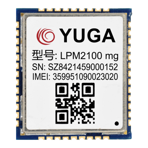
The LPM2100 bt is a multi-band NB-IoT series module that complies with 3GPP Release
13.
This series of modules has 98 pins, (23.6 ±0.15) mm ×(19.9 ±0.15) mm ×(2.2
±0.15) mm, which can meet almost all M2M requirements.
This series of modules is a chip module, which is packaged in LCC to meet the hardware
interface between the customer's motherboards.
The LPM2100 bt series modules feature low-power technology with standby power
consumption of less than 1mA and deep sleep as low as 5uA. Supports 2.45V voltage,
BDS/GPS/GLONASS/Galileo parallel reception and joint positioning.
Application
Smart city (smart parking, water/gas meters, street lights, smoke alarms, garbage bins,
manhole covers, containers, etc.)
Consumption and medical (wearing devices, VIP tracking, life support, remote clinical
tracking, etc.)

LPM2100 bt NB Module Hardware Usage Guide
Shanghai Yuge Information Technology Co., Ltd.
- 9 -
Industrial and agricultural intelligent monitoring (machine alarm, gas detection, irrigation,
soil pH, etc.)
Agriculture and the environment (agricultural applications, environmental monitoring,
etc.)
Logistics support (industrial assets, container tracking, location and status updates, etc.).
"*" indicates that it is under development.
"LPM2100 bt" is a collective term for the LPM2100 bt Nb-IoT series modules in the
documentation.
2.2 Main performance
Table 2-1 Key Features
Characteristic
Description
Physical
characteristics
(23.6mm×19.9mm×2.2mm) ±0.15mm
Application
processor
192MHz MIPS processor with 16KB I-Cache and 16KB D-Cache
Operating Voltage
Low voltage: 2.45V - 3.1V typical voltage 3V
Atmospheric pressure: 3.1V - 4.2V Typical voltage 3.7V
Power saving
PSM mode power consumption < 5uA
Standby
Sleep mode current < 1mA
Application interface
Power interface
Four-way universal GPIO interface
One-way standard SIM interface, support 3.0V/1.8V, support hot
swap function*
One way hardware reset interface
Two-way UART serial interface
One way SPI interface
One-way network status indication interface
All the way PSM_EINT# interface
One way ADC detection interface
Working frequency
Tri-band: Band3, Band5, Band8

LPM2100 bt NB Module Hardware Usage Guide
Shanghai Yuge Information Technology Co., Ltd.
- 10 -
GNSS positioning
characteristics
BeiDou/GPS/GLONASS/Galileo (bt_g or bt
module)BeiDou/GPS:B1-1561.098MHZ/L1-1575.42MHZ
AGPS
跟踪灵敏度: -162dBm
捕获灵敏度: -148dBm
冷启动 TTFF: ≤30s
热启动 TTFF: ≤1s
重捕获 TTFF: ≤1s
定位精度: <3m
测速精度: <0.1m/s
数据格式:NMEA 0183 可定制
Network protocol
feature
UDP/TCP/CoAP/LWM2M
PPP/SSL/DTLS/FTP
HTTP/MQTT/HTTPS
Data transmission
characteristics
Single-tone:25.5kbps(DL),16.7kbps(UP)
Multi-tone:25.5kbps(DL),62.5kbps(UP)
Antenna interface
Main antenna 50 ohm interface
GNSS antenna 50 ohm interface
Firmware upgrade
Serial port upgrade
temperature range
Normal operating temperature –20°C to +70°C
Extreme operating temperature –40°C to +85°C
Storage temperature: -45°C to +90°C
AT command
Support for standard AT instruction sets (Hayes 3GPP TS 27.007
and 27.005)

LPM2100 bt NB Module Hardware Usage Guide
Shanghai Yuge Information Technology Co., Ltd.
- 11 -
2.3 Module functional block diagram
The functional block diagram of the LPM2100 bt series module mainly includes the
following units:
Baseband processing unit
Power management unit
RF transceiver unit
RF front end unit
Peripheral interface.
The functional block diagram of the LPM2100 bt series module is shown below:
Figure 2-1 Functional block diagram of the LPM2100 bt series module
2.4 Module working mode
Table 2-2 Working mode
Operating mode
Description
Shut down
Module does not work in shutdown
Flight mode
The module turns off the module RF circuit and cannot interact
with the network.
Sleep
The module turns off most of the functions and will be
synchronized with the network.
Idle
Power on and successfully register the network, in idle state
Data transmission
The module is working and has data interaction with the network.

LPM2100 bt NB Module Hardware Usage Guide
Shanghai Yuge Information Technology Co., Ltd.
- 12 -
PSM mode
After entering the PSM mode, the module can achieve the
minimum power consumption, and the internal power of the
module is turned off. The software except the RTC stops running,
and the serial port cannot be used.

LPM2100 bt NB Module Hardware Usage Guide
Shanghai Yuge Information Technology Co., Ltd.
- 13 -
Chapter 3. Interface application description
3.1 Chapter overview
The LPM2100 bt series modules have a total of 98 pins and include the following partial
unit interface functions. The functions of each unit interface will be described in detail in later
chapters.
Power interface
SIM interface
UART interface
Network status indication interface
SPI interface
RF antenna interface (RF main antenna / GNSS antenna)
I2C interface.
3.2 Module interface
3.2.1 LPM2100 bt Pin map
LPM2100 bt pin assignment is as follows:

LPM2100 bt NB Module Hardware Usage Guide
Shanghai Yuge Information Technology Co., Ltd.
- 14 -
Figure 3-1 LPM2100 bt pin assignment diagram
①1 This module generally has a IO port level of 1.8V (SIM card port level supports
1.8V and 3.0V).
②2 This module defines that the NC pin is floating and must not be used.
③The module WAKEUP (PSM_EINT) pin voltage domain is 1.1V。
3.2.2. Module pin description
The module interface pin definition is described below:
Table 3-1 Pin Parameter Abbreviations
Symbol sign
Description
IO
Input or output
PI
Power input
PO
Power Output
AI
Analog input
AO
Analog output
DI
Digital input

LPM2100 bt NB Module Hardware Usage Guide
Shanghai Yuge Information Technology Co., Ltd.
- 15 -
DO
Digital output
Table 3-2 Interface definition
Pin
Pin name
IO
Functional description
Remarks
powered by
45,46
VBAT
PI
Module power supply
Input voltage
2.45~3.1V
3.1~4.2V
26
VDD_EXT
PO
Internal regulated power
supply output 1.8V
Can be left
unconnected when
not in use
System switch control
15
RESET
DI
Hardware reset control,
active low
SIM interface
16
SIM_DECT
DI
SIM card hot plug detection
Internal level has
been pulled up
38
SIM_VDD
PO
Output to the SIM card
supply voltage
Keep away from
interference sources
39
SIM_RST
DO
SIM card reset output
Keep away from
interference sources
40
SIM_DATA
IO
SIM card bus data
Internal 10K pull-up
resistor
41
SIM_CLK
DO
SIM card clock output
Keep away from
interference sources
42
SIM_GND
SIM card Groud
GND
Status indication
18
NETLIGHT
DO
Network status indication
1.8V voltage
domain
Main serial interface
22
CTS
DO
Clear send
1.8V voltage
domain
23
RTS
DI
Request to send
1.8V voltage

LPM2100 bt NB Module Hardware Usage Guide
Shanghai Yuge Information Technology Co., Ltd.
- 16 -
domain
29
RXD
DI
Master data reception
1.8V voltage
domain
30
TXD
DO
Master data transmission
1.8V voltage
domain
Debug serial interface
19
DBG_RXD
DI
Module debug data
reception
Debug serial port
20
DBG_TXD
DO
Module debug data
transmission
Debug serial port
UART1 Serial port
27
RXD1
DI
Data reception
1.8V voltage
domain
28
TXD1
DO
Data transmission
1.8V voltage
domain
I2C interface
32
SCL
DO
I2C bus clock output
Internal 10K resistor
pull-up
33
SDA
IO
I2C bus data input and
output
Internal 10K resistor
pull-up
SPI interface
3
SPI_DI_1
DI
Host input slave output
1.8V voltage
domain
4
SPI_DI_0
DO
Host output slave input
1.8V voltage
domain
5
SPI_CLK
DO
Serial clock signal
1.8V voltage
domain
6
SPI_CS
DO
Chip select signal
1.8V voltage
domain
CHARGE interface
8
VBAT_TS
DI
Battery in-position detection
Can be left
unconnected when
not in use

LPM2100 bt NB Module Hardware Usage Guide
Shanghai Yuge Information Technology Co., Ltd.
- 17 -
11
AC_ISENSE
DI
Charging current size
detection
Reserved
12
AC_GDRV
DO
Control external NMOS
charging pin
Reserved
13
AC_R
DI
External charge detection
interrupt pin
Reserved
14
AC_DIV_IN
DI
External charger voltage
detection pin
1/3 partial pressure
is required for use
ADC function pin
21
ADC
AI
Universal analog to digital
converter interface
1.8V voltage
domain
Universal input and output interface
31
GPIO_15
IO
Universal input/output port
35
GPIO_14
IO
Universal input/output port
36
GPIO_43
IO
Universal input/output port
37
GPIO_42
IO
Universal input/output port
Antenna interface
53
RF-ANT
IO
RF antenna interface
50Ωcharacteristic
impedance
1
GNSS-ANT
AI
GNSS antenna interface
50Ωcharacteristic
impedance
Other function pins
9
V_VIB
PO
Vibration drive
Reserved
10
V_RTC
PO
Output supply voltage
1.1V voltage
domain
17
WAKEUP
(PSM_EINT)
PI
Hardware control PSM pull
high wake up
1.1V voltage
domain
34
WAKEUP_O
UT
DO
Wake up host
1.8V voltage
domain
7,24,25,44,49
,50,55,56,57,
58,67,68,69,
70,75,76,77,7
NC
NC
Leave empty when
not in use

LPM2100 bt NB Module Hardware Usage Guide
Shanghai Yuge Information Technology Co., Ltd.
- 18 -
8,79,80,84,85
,86,87,88,89,
90,91
2,43,47,48,51
52,54,59,60,
61,62,63,64,
65,66,71,72,
73,74,81,82,
83,92,93,94,
95,96,97,98
GND
Ground signal
3.3 Power interface
LPM2100 bt series module power interface consists of two parts:
VBAT is the working power of the module;
VDD_EXT is an internal LDO 1.8V output supply (current load up to 50mA) for external
use。
The power supply VBAT voltage input range is 2.45V~3.1V (3.1~4.2V). The module
powers the internal RF and baseband circuitry through the VBAT pins. Under the premise of
ensuring that the VBAT power supply is sufficient, it is recommended to be close to the power
input and put 10pF, 0.1uF, 1uF ceramic capacitor and 100uF tantalum capacitor. VBAT PCB
traces are as short and thick as possible。
Figure 3-2 VBAT power supply
①To prevent damage to the module from surges and overvoltages, it is recommended
to connect a 5.1V/500mW Zener diode to the VBAT pin of the module.

LPM2100 bt NB Module Hardware Usage Guide
Shanghai Yuge Information Technology Co., Ltd.
- 19 -
②It is recommended to add multiple capacitance capacitors (10pF, 1uF, 100nF, 100uF)
to the VBAT pin and place them near the VBAT pin.
3.4 VDD_EXT Voltage output
After the LPM2100 bt series module is powered on normally, the 26th pin will output
1.8V and the current load will be 50mA. The external master can read the voltage of
VDD_EXT to judge whether the module is powered on. VDD_EXT can also be used as an
external power supply, such as a level shifting chip.
Figure 3-3 VDD_EXT power output timing diagram
3.5 Switching machine reset mode
3.5.1 Boot
The LPM2100 bt series module VBAT is automatically powered on after power-on. The
user can check whether the module is powered on by querying the high and low levels of the
VDD_EXT pin.
3.5.2 Boot timing
Figure 3-4 boot timing diagram
Table 3-3 Boot timing parameters

LPM2100 bt NB Module Hardware Usage Guide
Shanghai Yuge Information Technology Co., Ltd.
- 20 -
Symbol
Description
Min
Typical
Max
Unit
Tdelay
TBD
-
s
Ton(status)
Boot time (according to status status)
TBD
-
s
Ton(uart)
Boot time (according to uart status)
TBD
-
s
3.5.3 Module shutdown
The LPM2100 bt series module shutdown can be powered down via the VBAT pin and
shut down using the AT “at+cpof”command.
When the module is powered on, the VBAT pin stops the power supply module and shuts
down.
Figure 3-5 Shutdown timing diagram
Table 3-4 Shutdown timing parameters
Symbol
Description
Min
Typical
Max
unit
Toff
TBD
-
s
Toff(status)
Shutdown time (according to status status)
TBD
-
s
Toff(uart)
Shutdown time (according to uart status)
TBD
-
s
3.5.3 Reset control
The PIN15 signal of the LPM2100 bt series module is the RESET reset pin. The
application detects that the module is abnormal. When the software does not respond, the
module can be reset. Pull the pin low for 100-450ms to reset the module. The RESET pin is
sensitive to interference. A 10 nF to 0.1μF capacitor can be placed near the signal for signal
filtering. Keep away from RF interference signals when routing.
Other manuals for LPM2100 bg Series
1
This manual suits for next models
3
Table of contents
Other YUGE Computer Hardware manuals