ZAGI 400 ELECTRIC User manual

=ZAGI-400=
=ELECTRIC=
Wing Span 48"
Wing Area 2..833 sq. ft.
Airfoil Zagi 999
Weight 19 oz.
Loading 5.7 oz/sq. ft.
Radio 3channelsw/mixer
TRICK R/C Products LLC 938 Victoria Avenue Venice, California 90291
Assembly Manual

Recommendations and Notes
To avoid injury or damage to electronic speed control, Do not plug the battery into the speed control
until all of the steps have been followed on page 14.
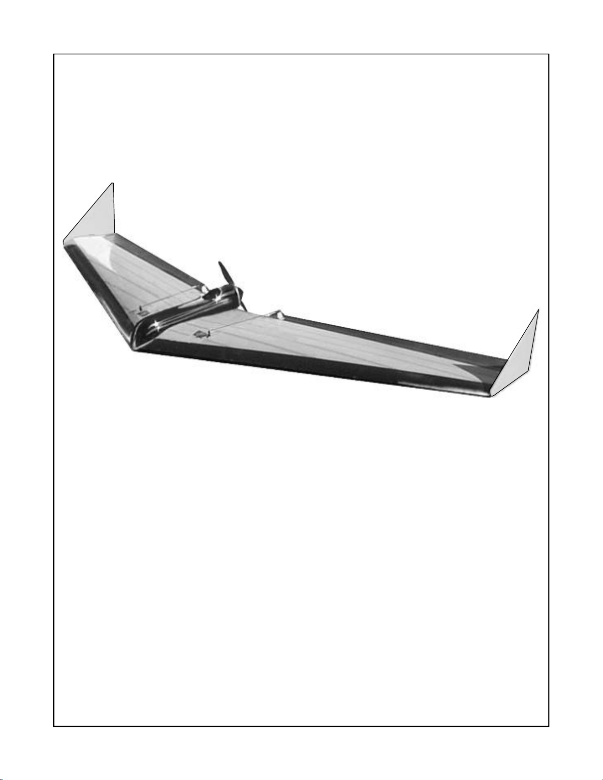
The ZAGI-400 is not a combat or bungie launch airplane. The design objectives
were to make a rugged low cost, light weight electric flying wing.
Read the entire manual before beginning construction!
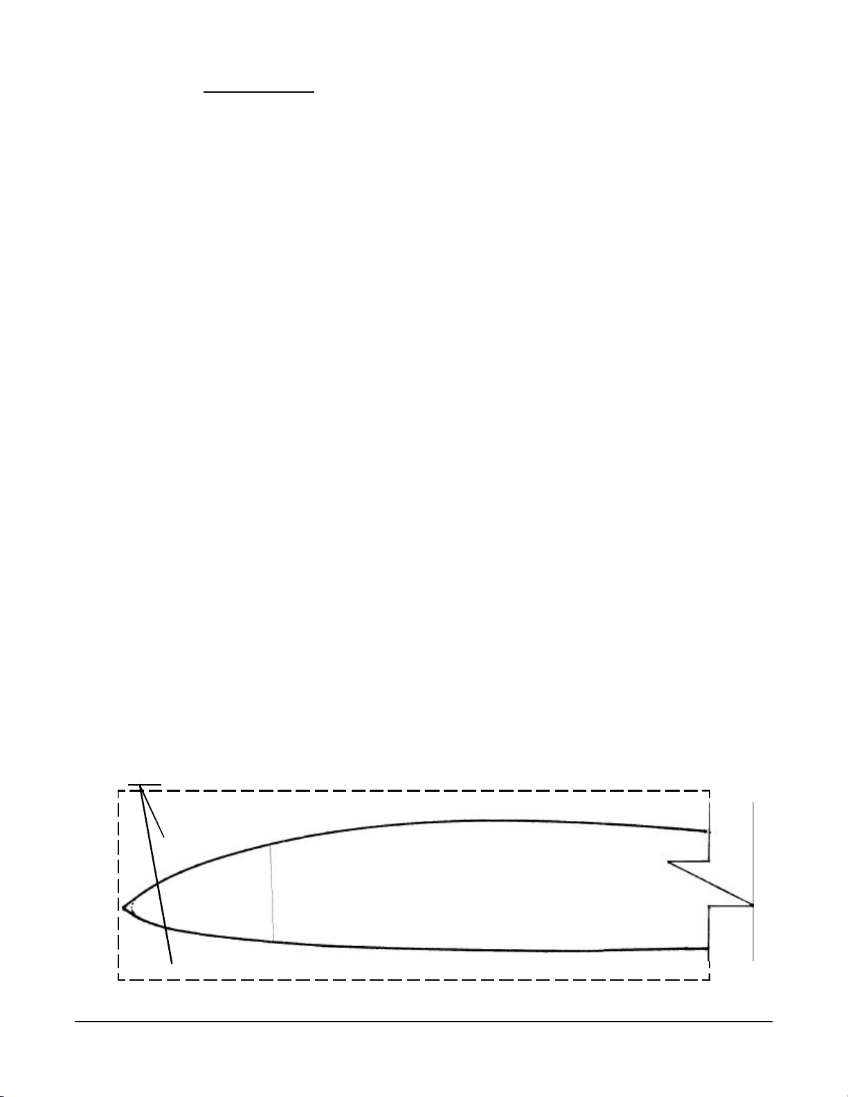
The target weight for the Zagi-400 is 19 oz. The airplane is designed to balance at 8”
measured back from the nose. In order to achieve these two objectives, a speed 400
motor, micro servos, and a 500 mAh 7 or 8 cell battery pack must be used. Any modifi-
cations, reinforcements or substitutions not described in this manual must be considered
carefully to maintain the correct weight and balance. If all of the procedures in this manual
are followed, the Zagi-400 will not need nose weight.
A separate battery is not required for the receiver and servos. They are powered by the
500 mAh battery through the Electronic Speed Control (ESC) which contains the Battery
Elimination Circuit (BEC). When the motor drains the battery there is still sufficient power
to control the plane.
Larger radio components are not recommended.
The manufacturer did not test any covering materials such as UltraCote, MonoKote,
Solarfilm, or any other iron-on materials. If an alternate covering material is chosen, test a
patch on the beds first. Lower heat will be necessary when covering the 1# white foam.
Do not cut into any part of the leading edge foam for the radio installation or nose weight.
Do not use polyester resin, solvents, or solvent-based paint on either type of foam.
Tools and materials needed:
Optional - a roll of contrasting color poly tape (see text)
90 degree square
Sanding block
150 to 320 grit sandpaper
X-Acto knife or Dremel
Round pencil or ball-point pen
Spray adhesive (3M Super 77 or similar)
3/4” fiber filament tape (2” filament tape optional - see text)
Solderingiron
page 2

The ZAGI-400 Complete Kit Electric Wing Kit contents:
2Expanded polypropylene (EPP) leading edges
laminated to 1# white foam wing panels and beds
2Pre-cut balsa elevons
224’’ strips of 1’’ x 3 mil paper backed Mylar hinge tape
1Roll 2.2 mil color poly tape
2Control horns with 4 screws
2Threaded 2 X 56 push rods
2Threaded 2 X 56 clevises
2Die-cut clear plastic winglets
1Molded motor mount and battery tray
1Molded canopy
1Speed 400 motor and prop
1
Zagi20 Electronic SpeedControl (ESC) withBattery Eliminator Circuit (BEC)
17 or 8 cell 500 mAh battery with Deans Ultra plug
2Tie wraps to secure motor
4Velcro strips for canopy and battery hold down
1Deans Ultra plug with red and black leads (for charging the battery)
Needed Components:
1Mini or micro receiver with crystal for your transmitter channel
Suggestions: Hitec 555 or comparable
2Mini or micro servos. Suggestions: Hitec HS-81 or HS-85BB; Cirrus CS-20
series, CS-30, or comparable. Servos are available with metal gears (HS-
81MG), providing added protecion from gears stripping on hard impact.
page 3
(See Figure 1) Separate the top and bottom beds from the wing cores. Lightly block
sand the wing panels (cores) with #150 or #320 grit sandpaper and round the leading edge
(LE).
Beds
Wing Core
Figure 1

Optional Procedure
A smooth finish can be obtained using light weight spackling with a minor weight penalty. Apply
the spackling to the 1# foam only and not on the EPP leading edge. Apply a thin coat of lightweight
spackling with a 4 inch wide squeegee. Let the spackling dry. Sand to a smooth finish with 320 grit
sandpaper.
Vacuum the dust from the cores, beds and the work bench. Lay the wing in the beds top-side up. Apply a light
coat of 3M Super 77 spray adhesive to cover the top of the entire wing. Allow the adhesive spray to dry at
least 30 minutes. Repeat this procedure on the other side.
The fiber tape schedule described in Figure 3 is intended for aerobatics and thermal applications. If
the tasks for the Zagi-400 will include high-speed dives, the fiber tape must be increased to three
side-by-side strips instead of only one or use 2” fiber tape. The two-inch tape I used increased the
flying weight by ½ ounce.
(See Figure 3)
Laythewingtop-sideupinthebottom beds. Apply a strip of 3/4’’ fiber filament tape along
the trailing edge between the wing tip and the prop cutout. Apply another strip to the trailing edge to extend to
theopposite leading edge. Apply two spanwisestripsof tape at themotortray cutout extending to theleading
edge on both sides. Apply anothertwospanwise strips of 3/4’’ fibertapein the center of thewing 4’’ from
the motor tray cutout. Apply two strips of fiber tape diagonally from the nose to the outboard tip of the trailing
edge. Lay the wing bottom-side up in the top beds and repeat the same taping procedure on the bottom side.
page 4
2 1/2’’
5’’
Figure 2
12”
Layout the bottom beds on a flat surface. Tape them together. Repeat for top beds. Align the cores together
on the bottom bed. Spray the root end of the wing cores with #77 spray adhesive. Put a piece of clear wrap
or wax paper between the beds and the cores to prevent sticking. Let the adhesive dry for 10 minutes. Put the
wingcorestogetherusingbedsasajig.
(See Figure 2)
Measure 12” from the nose along the center line and make a mark. Use a square to measure
21/2’’ on both sides ofthecenter line. Mark the 5”lineand make two lines paralleltothe center line fromthe
endsof the line tothe trailing edge (TE). Cutalongthe lines and removethe foam.

(See Figure 4) Lay the wing in the top bed bottom-side up. Start the tape covering at
the trailing edge (TE) of the wing by wrapping a strip of color tape around the TE being
careful to follow the shape. Working from the TE forward, lay strips of tape from tip to
at least 4 inches past center. Overlap the tape only 1/4" all the way from the center to
the tip. Cut the tape to match the angle of the leading edge. Place the wing top-side up in
the bottom bed and repeat the taping procedure working from TE forward to the LE.
Finish the leading edge with a single spanwise piece of tape wrapped around the LE.
page 5
Figure 4
Wrap the first strip of
tape around the TE
Cut the tape at
an angle at the LE
Wrap the leading edge
with a single spanwise
piece of tape
Overlap the tape only
1/4"
Overlap at least
4 inches past
center
Figure 3
4”

(See Figure 5) Hold the elevons together and sand them until they are identical. Trim the
outboard end to match the angle of the wing tip. Trim the inboard end of the elevon to
match the angle of the motor cut-out. Make the elevons about 1/16” shorter than the wing
tip to make sure the elevons don’t rub against the winglets after they are installed.
(See Figure 5A) Round the top of the trailing edge of the elevon. Sand a 45oangle into
the front of the elevon.
Spray the elevons with any spray enamel. Primer works well. Apply a light coat of paint
and immediately wipe it with a cloth before it soaks in and dries. Let the paint dry and
repeat the procedure one more time.
(See Figure 6) Make sure that the paint is dry. Position the elevon on the trailing edge of
the wing with small pieces of masking tape on the bottom side. Move the elevon to check
for binding. Peel the paper backing from the 1” x 3 mil Mylar hinge tape. On the top
side, align the hinge tape by holding the peeled paper over the seam. Secure the elevon by
pressing the hinge tape in place at one end. Press the hinge tape down along the length of
the elevon. Remove the masking tape. Make a tape hinge the full length on the top side of
both elevons.
page 6
Figure 6
Remove this material
Figure 5
Trim ends
to match
Figure 5A
Tape hinge

page 7
(See Figure 7) The control rods may not fit in the servo control arm. The end of the
control rod can be filed to fit in the servo control arm or the top hole in the servo control
arms can be reamed by spinning an X-acto #11 blade in the hole or drilling with a #48 drill
(.076”). Attach control rods to the servo control arms with a Z-bend. (NOTE: Z-bend
pliers may be purchased from your local hobby store to make this operation easier).
Position the control horns on the elevon directly behind the servo control arm close to the
hinged edge but be sure the control horn and screw plate do not interfere with the move-
ment of the elevon. Mark the position of the control horns. Drill two holes. Install the
control horns on the elevons. Note that the two screws will self thread into the plastic
screw plate. Attach the control rods to the top hole of the servo control arms. Attach the
clevises to the control horns. It may be necessary to put a slight bend in the control rod
about 1 inch from the servo to prevent hitting the wing. Beginning flyers put the clevis on
the 1st or 2nd hole from the top of the control horn for less response. Experienced flyers
put the clevis in the 3rd or 4th hole from the top for more response.
Figure 7
Make a Z-bend by making two 90 degree
bends in the control rod. Push the rod
through the servo output arm.through the
servo output arm.
Top view
of the servo
control arm
Control horn
Threaded Clevis

page 8
(See Figure 8)
Position the servos on the pre-marked servo positions. Outline the exact
shape. Cut or router the foam to provide a snug flush fit. Wood shims can be used to
assure a tight fit. Position the receiver 6 1/4” back from the nose. Position the receiver so
that the input slots align with the centerline of the wing. Outline the exact shape. Cut or
router the foam to provide a snug flush fit. A separate bay can be made next to the re-
ceiver bay to hold a separate mixer. Cut the bay wider so that the mixer and all of the
plugs and extra wires fit underneath.
Draw a line perpendicular to the center line from each servo wire to about 1/4” from the
center line of the wing. Continue the lines parallel to the center line down to the receiver.
Make a 1/2” deep cut along the lines. Push the servo wires into the slot with a flat blade
screwdriver. Plug the servo leads into the appropriate receiver output slot, typically the
right servo in slot 1 and the left servo in slot 2. The extra servo wires can be stowed
under the motor mount tray.
Trim the motor tray with scissors along the cut line. Notice that the cut line is the impres-
sion 1/2” from the side rails of the compartments. Leave the vertical lip at the rear of the
motor. Position the motor tray over the center of the wing. Trim the vertical lip at the rear
of the motor tray to be flush with the bottom of the wing. Check the receiver position.
Make a cut-out in the rear bay of the motor tray to provide access to the input slots of the
receiver. Mark the antenna layout. Draw a line to the leading edge seam. Continue the
line spanwise to the wing tip. Cut a 1/4” slot along the line. Push the antenna into the slot
with a flat blade screwdriver. The antenna will extend beyond the tip.
Cut-out tray for
receiver access
Antenna wire
Make a 1/2” deep
cut along the line
Figure 8
Receiver
6 1/4”

(See Figure 10)
TheZagi-20ESC(Electronic Speed Control) is provided in thekit. Theredandblackpair
ofwireswiththe red male Deans Ultraconnectorplugsintothe battery. The red and blue pairofwireswiththe
separatespadeconnectorsplug into the motor. The Zagi-400usesapusherconfigurationwhich requires a
reverserotationmotor. Reversing the rotation of themotoris achieved by reversing thepolaritytothe motor.
Look at the flat surface on the back of the motor. Observe the red dot next to one of the motor terminals. For
apositive connection, solder thespade connectors tothemotor terminals, thebluewire on theterminal next to
thereddot. The third set of wiresisthethree wire ribbon lead withtheuniversalRX servo connector. This RX
connectorgoestoslotinthereceivertocontrolmotorspeed. Thethreewireribbonconnectorwillprovide
powerforthe receiver and servos. No other receiverbatteryisnecessary. Theuniversal connector will work
withallradios except the oldAirtronics. Thered and black wires mustbereversed in the plastic housingofthe
universalreceiver plug to change totheold Airtronics system.
Make a strain relief to protect the ESC wires from damage on impact. Tether the Deans connector on the ESC
tothemotorwiretie with a length of dental floss. The tetherwillunplugthebatteryonimpactratherthanpulling
wires out of the ESC.
Caution: The speed control turns on when the battery is plugged in. Attach the
red and blue wires to the motor before the ESC is plugged into the battery. The propSHOULD NOT
be installed on the motorat this time.
Figure 10
Motor
Spade Connector
RedDeans
UltraPlug
Universalreceiverplug Red and Blue wires
Red and Black wires
Receiver
Strain relief
Ribbon wire
Motor mount
wiretie
ESC
(Figure9)
Trim the canopy along the cut line. The canopy cut lines are more visible when viewed from the
inside. Remove the rear wall of the canopy. Cut out the oval shaped flat surface to make a vent for motor
coolingon thecanopy.
Cutout the oval
shaped flat surface
Figure 9
page 9

(See Figure 11) Attach the motor to the tray with a tie wrap. Locate the dimples on the
rails on either side of the motor mount. Spin an X-acto blade in the dimples to make a
hole. Elongate the holes to fit the wire tie. Push the wire tie through from the top of the
tray. Wrap the wire tie under the motor tray and through the hole on the opposite side.
Set the motor in the motor mount and push it back against the stop. Thread the wire tie
and pull it tight. Hold the tail of the wire tie with pliers and give it a good strong tug. Trim
the tail off of the wire tie. Slide the wire tie connection to the side of the motor.
page 10
RECEIVER
RED DEANS ULTRA PLUG
RIBBON WIRE FROM ESC
TO RECEIVER
REDWIRE
ESC
Figure 11
WIRE TIE

(See Figure 12) Align the motor tray with the nose. Make sure that the motor tray is
centered over the center line at the trailing edge. Attach the motor tray with a strip of
fiber tape on each side. Cover the servos with strips of color tape.
(See Figure 12) Peel the protective paper off of the hook side of two 1” squares of
Velcro. Stick the strips to the battery 1/2 inch from each end. Press the loop side to the
hook side and peel the paper. Press the battery in place with the sticky side down.
(See Figure 12) Cut the two 1” square Velcro pieces into four 1/2” x 1” pieces. Stick
the hook side of one of the strips of Velcro to the nose of the motor tray. Stick the hook
side of one of the strips of Velcro to either side of the back of the motor tray. Put the
loop side of the Velcro loop side down on the hook side. Peel the paper off of the loop
side. Place the canopy over the motor tray, nose first. Spread the back end of the
canopy and lower it onto the motor tray.
Velcro
Battery
page 11
Velcro
Tape the tray down
with fiber tape
Cover the servos
with color tape.
Figure 12

page 12
(See Figure 13) Punch-out and separate the two nested clear winglets. Punch-out the 1
1/4" x 1/4" slot in the winglet.
(See Figure 14) Put a piece of fiber filament tape through the slot to the top of the wing
and wrap it around to the bottom of the wing. Add two more pieces of tape to secure the
winglet in place. Make sure that the elevon will not bind against the winglet as it moves.
The winglets are at the very back of the airframe so they will seriously impact the
balance of the plane. The tape method of fastening is both light and strong. If a
different winglet fastening system is preferred, keep the weight down to the weight
of three short strips of tape.
Fiber tape
Figure 14
Figure 13

Figure 16
(See Figure 16)
With the TX on and the battery plugged in, set the elevon neutral setting by laying a straight
edgeunderthe wing at thetrailingedge. Theelevons should appear to have2or3 degrees of reflex(up
elevator).
(See Figure 15)
Lay wing bottom-side-up. Using a square, mark the CG by making a line perpendicular to the
center line 8" back from the nose on both panels. Tape a 1/4” dowel directly over the CG line. A round pencil
orball-pointpencanbeused. Placethewingright-side-uponaflatsurface. Balanceisachievedwhenthe
wingbalances momentarily onthe pencil. Add lead noseweight under the batterytray if necessarytoachieve
balance.
page 13
8 inches
Figure 15
Setthe trimand throw.
Movethetransmitter aileron stick from full right to full left (not up or down).
Theelevon throwshouldbe3/8" ineachdirectionmeasured 1"fromthetip (nodifferential) Whenmovingthe
elevatorstick full up to fulldown, the throw should be3/8"in each direction.
Reverse the prop.
Thepropmustbereversedtooperatein the reverse direction. The raised lettering on the
propellerblades should beon the spinnerside. Remove the spinnerand hub. Hold the prop by the blades
spinner side up. Press it on a flat surface. Grip the spinner and gently twist and pull the hub from the prop.
Reverse the prop and replace the hub so that the raised lettering is on the spinner side of the prop, outside and
awayfrom themotor.

page 14
First time motor power-up
The following steps are provided for a safe first time power-up of the motor. Do not
press the prop onto the motor shaft yet. Test the motor hook-up before the prop is in-
stalled. Make sure that the battery is charged. The batteries are not shipped with a
charge.
SANYO RECOMMENDS CHARGING THE N-500A CELL AT A RATE UP TO 500 MA
FOR THE LONGEST BATTERY LIFE. 500 MA WILL CHARGE THE 7 OR 8 CELL
BATTERY IN ONE HOUR. AT THE RISK OF A SHORTER BATTERY LIFE, SOME
MODELERS REGULARLY CHARGE THEM FOR 30 MINUTES AT 1 AMP. IF THIS
CHARGE RATE IS UNSATISFACTORY, YOU NEED N-500AR CELLS. N-500AR CELLS
WILL CHARGE IN 15 MINUTES AT A RATE OF 2 AMPS .
1. Make sure that the motor is seated against the forward stop and securely attached to the motor mount.
2. Makesure that the reverse switch forthemotor stick on the transmitterisin the normal position. Not
reversed!
3. Push the motor control stick on the transmitter to the full down position.
4. Pushthemotorcontrolstick trimlever (nextto themotor stick)to thefull down position.
5. Turn the transmitter power on. Check the output meter for battery condition.
6. Securethe charged battery inplace with the Velcro tabs.
7. Plug the ESC JR connector into the motor slot of the receiver, typically slot 3.
8. Position yourself with the nose of the airplane pointed at you. Plug the battery into the speed control.
9. Check that the red LED on the ESC circuit board is on.
10. Move the trim lever for the motor control stick slowly upward to the center position. The motor should
notmove.
11. Move the motor control stick slowly upward. The motor should run faster the further up the stick is
moved. The motor shouldturn counter clockwise when observed from the front.
12. Unplug the battery from the speed control. Press the prop onto the motor shaft. Make sure you seat
the adapter on the shaft fully. This may take quite a bit of force. To make sure you know how far to
push, put a pin in the adapter hole, and mark the pin with the depth. Compare that marked pin to the
motor shaft. This will give you an idea of how far to push. Rotate the prop to make sure it is clear of
any obstructions.

Preflight check and glide test
Do a preflight check before every flight. Always turn the transmitter power on before the
motor battery in the airplane is plugged in (and un-plug the battery before turning off the
TX). Make sure that the motor control stick is in the full down position. Make sure that
the controls are working properly. Check the trim levers on the transmitter. Pull the con-
trol stick back and observe that both elevons move upward. Push the control stick to the
right and observe the right elevon moves up and the left elevon moves down. Hold the
Zagi-400 securely by the nose. Move the throttle stick to the half throttle position momen-
tarily. The first glide test should be done on flat land in a light breeze. The Zagi-400
should be held by the nose with your palm up over your head and your thumb wrapped
around to the top. (See figure 17) Hold the Zagi-400 over your head with the nose
pointed straight ahead. Run slowly into the wind. Give it a gentle push STRAIGHT
AHEAD. Do not point the nose upward. Correct the flight path with the radio control
stick. The test is successful when the Zagi-400 flies straight ahead with a slow sink rate to
a sliding landing. If the Zagi-400 turns in either direction after the launch, compensate by
adding 2 or 3 clicks of trim in the opposite direction with the trim lever below or next to
the control stick. If the Zagi-400 pitches up and immediately dives, add 2 or 3 clicks of
down trim. Repeat the glide test until the Zagi-400 flies straight ahead with a slow sink rate
to a sliding landing. Increase the launch speed each time to provide longer control flights.
First flight
IMPORTANT: Please check the frequencies (channel number) of all pilots at your
site before turning on your transmitter. Turning on your transmitter with the same
channel number as someone who is flying will certainly cause his plane to crash.
CAUTION: While the Zagi-400 is made of foam, traveling at a high rate of speed
can cause considerable damage to someone or something if a collision occurs.
Please exercise caution while flying. It is recommended that you join the Academy
of Model Aeronautics (AMA) (1-800-435-9262) to provide insurance, awareness of
safe flying practices, and knowledge of what’s going on in the modeling field.
At some flying sites it is mandatory that you be a member of the AMA.
Do not launch the Zagi-400 with the motor running. Hold the Zagi-400 by the nose
with your palm up over your head and your thumb wrapped around to the top. (See
Figure 17) Take a step or two forward and give the Zagi-400 a good strong throw into
the wind. A follow through with a little finger tip will increase the launch speed. Slide the
throttle stick to the full forward position when the Zagi-400 is a comfortable distance from
the ground. Get some altitude and experiment with some throttle settings. Full motor is
fun but will use up the battery quickly. It is recommended that beginners fly at quarter
throttle until stick sensitivity is developed. Good luck.
JT Rev 09/01/01
page 15

Throwing the Zagi-400
Hold the Zagi-400 by the nose with your palm up over your head and
your thumb wrapped around to the top. The secret to this launch is
the energy you exert with your fingers in the follow through.
Figure 17
page 16
Trick R/C guarantees this kit to be free from defects in both workmanship and material at
the date of purchase. This does not cover any components or parts damaged by use,
misuse or modification. In no case shall Trick R/C’s liability exceed the original price of
the purchased kit.
Since Trick R/C has no control over the final assembly, no liability shall be assumed for
any damage resulting from the use by the user of the final user-assembled product. By the
act of using the final user-assembled product, the user accepts all resulting liability.
Tech Support (310) 827-2288
Revised09/01/01

Zagi is a registerd trademark of Trick R/C Products LLC
Table of contents
Other ZAGI Toy manuals
Popular Toy manuals by other brands

REVELL
REVELL Handley Page HALIFAX B Mk. III Assembly manual

Meccano
Meccano 15310 instructions

Playskool
Playskool Power Auto Repair Center instructions

Jamara
Jamara Ferrari LaFerrari instructions

Maya Group
Maya Group Orbeez Crush CRUSHKINS PETS Instruction guide

REVELL
REVELL Focke Wulf TL-Jager Flitzer Assembly manual

Pinolino Kinderträume
Pinolino Kinderträume Hoppetosse Assembly plan

Thames & Kosmos
Thames & Kosmos Robotics Smart Machines Track & Treads Experiment manual

Fisher-Price
Fisher-Price View-Master 3-D Viewer instructions

Philos
Philos 5520 manual

Gakken
Gakken Mechamo Inchworm Instructions for assembling and operating

Eduard
Eduard A-10 Thunderbolt II interior quick start guide