User Information
H. ZANDER GmbH & Co. KG • Am Gut Wolf 15 • 52070 Aache • Germa y
Tel +49 (0)241 9105010 • Fax +49 (0)241 91050138 • info@zander-aachen.de • www.zander-aachen.de
3
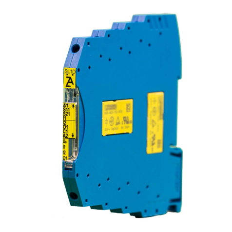
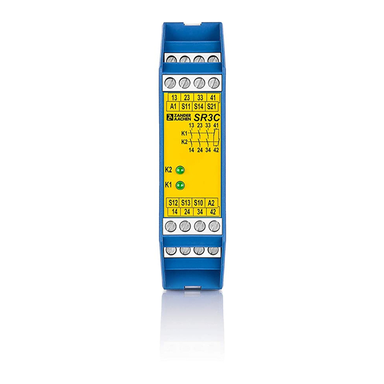
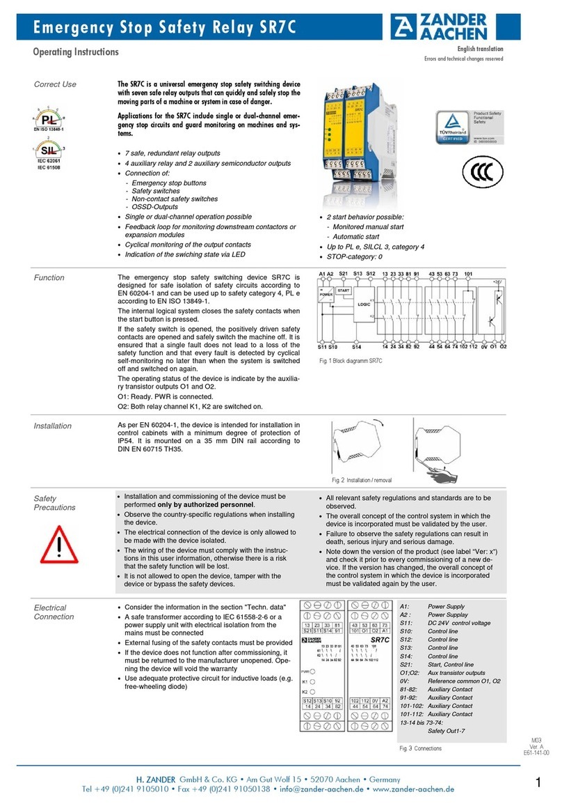
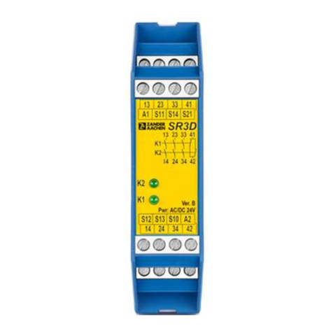
Safety Emergency Stop Relay SR3D
M03
Ver. B
E61-139-00
English translation
Errors and technical changes reserved
Techn. Data
In compliance with EN 60204-1; DIN EN ISO 13849-1; EN 62061; EN 50156-1;
EN 746-2; IEC 61508 Parts 1-2 and 4-7; IEC 61511-1
Operating voltage AC 230 V, AC 115 V, AC/DC 24 V
Rated supply frequency 50-60 Hz
Allowable tolerance + / - 10 %
Power consumption DC 24 V AC 230 V
approx. 2 W approx. 6.9 VA
Control voltage at S11 DC 24 V
Control current at S11...S14 max. 100 mA
Safety contacts 3 NO
Auxiliary contacts 1 NC
Switching voltage max. AC 250 V
Contact rating of safety contacts (13-14, 23-24, 33-34) *) AC: 250 V, 2000 VA, 8 A for resistive load
6 switching cycles/ min
250 V, 3 A for AC-15
DC: 30 V, 240 W, 8 A for resistive load
24 V, 3 A for DC-13
UL: C300 / R300
Cumulative current Max. 15 A (13-14, 23-24, 33-34)
Contact rating of auxiliary contact (41-42) AC: 250 V, 500 VA, 2 A for resistive load
DC: 30 V, 60 W, 2 A for resistive load
Minimum voltage/current 5 V, 10 mA
External fuses for safety contacts 10 A gG
6 A gG for applications acc. to EN 50156-1
(See Chapter 10.5.5.3.4)
Wire width 0.14 - 2.5 mm2
Tightening moment (Min. / Max.) 0.5 Nm / 0.6 Nm
Typ. switch-on delay / switch-off delay < 30 ms / < 20 ms
Length of control lines Max. 1000 m at 0.75 mm2
Contact material AgSnO2
Service Life mech. approx. 1 x 10⁷
Rated impulse withstand voltage 2.5 kV (control voltage / contacts)
Dielectric strength 4 kV (DIN VDE 0110-1)
Rated insulation voltage 250 V
Protection IP20
Temperature range DC 24 V: -15 °C bis +55 °C
AC 115 V / 230 V: -15 °C bis +55 °C
(see load curve)
Max. altitude ≤2000 m (above sea level)
Degree of pollution / Overvoltage category 2 / 3 (DIN VDE 0110-1)
Weight approx. 230 g
Mounting DIN rail according to EN 60715 TH35
*) If several SR3D-24V are mounted closely together the maximum cumulative current is 9A at an ambient temperature of
20°C or 3 A at 30 °C or 1 A at 40 °C. If the current exceeds these limits, keep a minimum space of 5 mm between the
devices.
5. Starting the device:
Switch on the operating voltage.
Warning:
If the “Automatic start” starting behavior is set, the safety
contacts will close immediately.
If the “Monitored manual start” starting behavior is set,
close the start button to close the safety contacts.
LEDs K1 and K2 are lit.
6. Triggering safety function:
Open the emergency stop circuit by actuating the connec-
ted safety switch. The safety contacts open immediately.
7. Reactivation:
Switch the device on again as described under 5.
Device cannot be switched on again after an emergency
stop:
•
Emergency stop circuit was closed again.
•
Was the start button opened before closing of the emer-
gency stop circuit (manual start)?
•
Is the feedback loop closed?
If the fault still exists, perform the steps listed under
“Commissioning Procedure”. If these steps do not remedy
Device does not switch on:
•
Check the wiring by comparing it to the wiring diagrams.
•
Check the safety switch used for correct function and
adjustment.
•
Check whether the emergency stop circuit is closed.
•
Check whether the start button (manual start) is closed.
•
Check the operating voltage at A1 and A2.
•
Is the feedback loop closed?
What to do in
Case of a Fault?
Caution: Opening the device is impermissible and will void the warranty.
Check and Mainte-
nance
The following checks are regularly required to ensure
proper and continuous functioning:
•
Check the switch function
•
Check for signs of manipulation and safety function
bypassing
•
Check if the device is mounted and connected securely
•
Ceck for soiling
Check if the safety device is working properly, in particular:
•
Every time after initial commissioning
•
Every time after replacing a component
•
After every fault in the safety circuit
Regardless of this, the safe functioning of the safety device should be checked at suitable intervals, e.g. as part of the mainte-
nance schedule of the plant. No maintenance is required for the device itself
