H. ZANDER GmbH & Co. KG • Am Gut Wolf 15 • 52070 Aache • Germa y
Tel +49 (0)241 9105010 • Fax +49 (0)241 91050138 • info@zander-aachen.de • www.zander-aachen.de 1
Time-Del. Emergency Stop Safety Relay SR4C
M11
Ver. A
E61-140-00
Operating Instructions English translation
Errors and technical changes reserved
• Cyclical monitoring of the output contacts
• Indication of the switching state via LED
• 2 start behaviors possible:
- monitored manual start
- automatic start
• Short circuit and earth fault monitoring
• Up to L e, SILCL 3, category 4
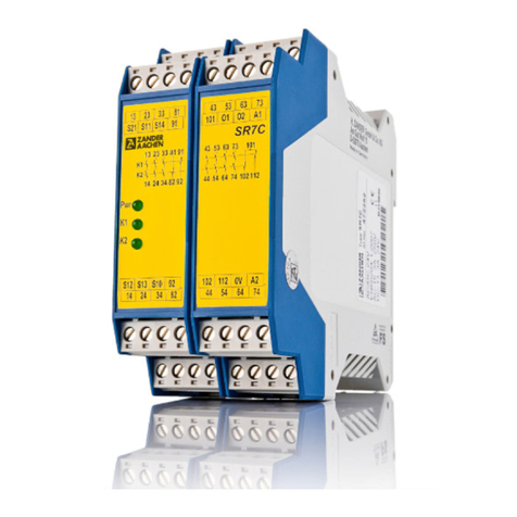
SR4C is an emergency stop safety relay com ination that
com ines non-time-delayed and time-delayed contacts in a very
compact housing. This permits dangerous components of a
system to e switched off quickly and safely in an emergency
situation. At the same time, other circuits can continue to e
supplied with voltage for up to 30 seconds to allow a tool to e
moved to its idle position or to rake following parts, for
example.
• 4 positively driven safety relays contacts. ossible vari-
ants:
- 3 non-time-delayed and 1 time-delayed contact
- 2 non-time-delayed and 2 time-delayed contact
- 1 non-time-delayed and 3 time-delayed contact
• Continuously adjustable time delay (1 to 30s).
• Connection of:
- Emergency stop buttons
- Safety switches
- Non-contacts safety switches
- OSSD-Outputs
• 1- or 2-channel activation possible
• Feedback loop for monitoring downstream contactors or
expansion modules
Function The moving parts of a machine or system can be quickly
and safely stopped in case of danger with the non-time-
delayed contacts of the SR4C Safety contacts with time-
delay switch-off are also integrated into the SR4C. They
are used whenever it is safer to keep supplying voltage to
parts of a machine after the emergency stop switch is
operated.
t is ensured that a single fault or malfunction does not lead
Installation As per D N EN 60204-1, the device is intended for installa-
tion in control cabinets with a minimum degree of protection
of P54. t is mounted on a 35 mm D N rail according to D N
EN 60715 TH35.
Safety
recautions
Fig. 2 Installation/removal
to a loss of the safety function and that every fault is detect-
ed by cyclical self-monitoring no later than when the system
is switched off and switched on again.
The time-delay contacts are activated at the same time as
the non-time-delay contacts; however, when the emergency
stop button is pressed, the contacts are only deactivated
after the time set on the potentiometer (1 … 30s).
During timeout, no power-loss is accepted.
Electrical
Connection
• Consider the information in the section "Techn. data"
• A safe transformer according to EN 61558-2-6 or a
power supply unit with electrical isolation from the mains
must be connected
• External fusing of the safety contacts must be provided
• f the device does not function after commissioning, it
must be returned to the manufacturer unopened. Ope-
ning the device will void the warranty
• Use adequate protective circuit for inductive loads (e.g.
free-wheeling diode)
Fig. 3 Connections nd non-time delayed; d time-delayed
Fig. 1 Block diagram: SR4C (1nd/3d); SR4C (2nd/2d); SR4C (3nd/1d)
A1: ower supply
A2 : ower supply
S11: DC 24 V control voltage
S10: Control line
S12: Control line
S13: Control line
S14: Control line
S21: Start control line
13-14: Safety contact 1 (nd)
23-24/27-28: Safety contact 2 (d / nd)
33-34/37-38: Safety contact 3 (d / nd)
47-48: Safety contact 4 (d)
• All relevant safety regulations and standards are to be
observed.
• The overall concept of the control system in which the
device is incorporated must be validated by the user.
• Failure to observe the safety regulations can result in
death, serious injury and serious damage.
• Note down the version of the product (see label “Ver: x”)
and check it prior to every commissioning of a new de-
vice. f the version has changed, the overall concept of
the control system in which the device is incorporated
must be validated again by the user.
• nstallation and commissioning of the device must be
performed only by authorized personnel.
• Observe the country-specific regulations when installing
the device.
• The electrical connection of the device is only allowed to
be made with the device isolated.
• The wiring of the device must comply with the instruc-
tions in this user information, otherwise there is a risk
that the safety function will be lost.
• t is not allowed to open the device, tamper with the
device or bypass the safety devices.
Correct Use
