manuals.online logo
Brands
  1. Home
  2. •
  3. Brands
  4. •
  5. zeeltronic
  6. •
  7. Controllers
  8. •
  9. zeeltronic PCDI-24V User manual

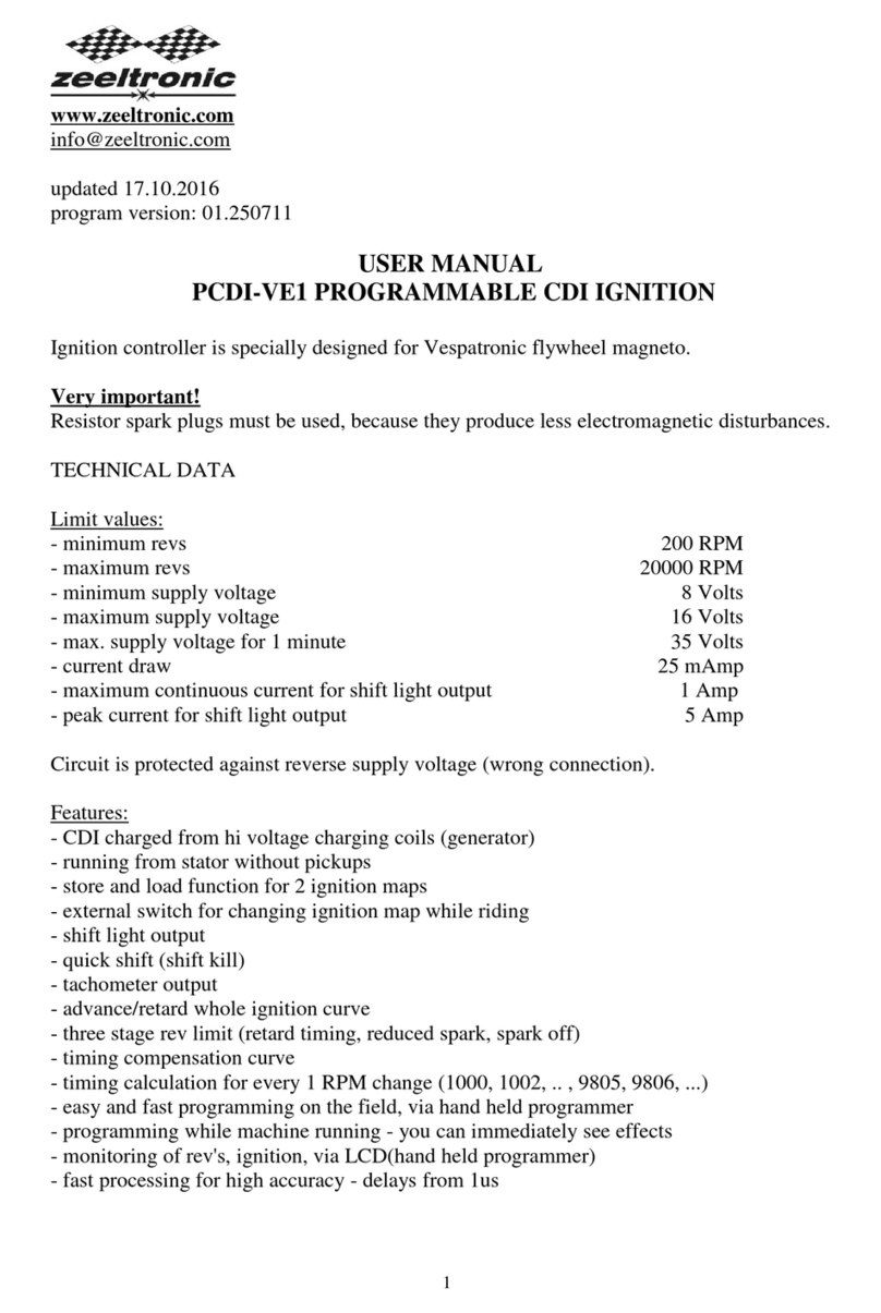
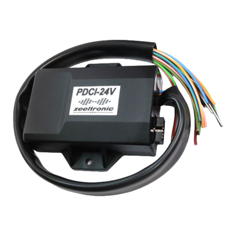
zeeltronic PCDI-24V User manual

- 1 -
www.zeeltronic.com
[email protected]
updated 14.01.2009
program version: 00.140109
USER MANUAL
PCDI-24V
PROGRAMMABLE CDI IGNITION AND PV CONTROLLER
TECHNICAL DATA
Limit values:
- minimum revs 200 RPM
- maximum revs 20000 RPM
- minimum supply voltage 8 Volts
- maximum supply voltage 16 Volts
- max. supply voltage for 1 minute 35 Volts
- current draw 25 mAmp
- maximum continuous current for shift light output 1 Amp
- peak current for shift light output 5 Amp
Circuit is protected against reverse supply voltage (wrong connection).
Features:
- CDI charged from hi voltage charging coils (generator)
- programmable ignition map (3D interpolated)
- store and load function for 2 ignition maps
- one input for magnetic pickup
- TPS input (ignition map is 3D interpolated above TPS33%)
- external switch for changing ignition map while riding
- power jet output
- quick shift (shift kill)
- tachometer output
- advance/retard whole ignition curve
- programmable timing offset between twin output (RD/RZ500)
- three stage rev limit (retard timing, reduced spark, spark off)
- signal delay compensation
- timing calculation for every 1 RPM change (1000, 1002, .. , 9805, 9806, ...)
- programmable power valve actuation
- store and load function for 5 PV curves
- programmable PV deviation
- programmable max close and max open positions
- self PV test on power-up
- 2 -
- PV error detecting (position sensor failure, servo motor failure)
- easy and fast programming on the field, via hand held programmer
- programming while machine running - you can immediately see effects
- monitoring of rev's, TPS position, ignition and PV angle, via LCD(hand held programmer)
- fast processing for high accuracy - delays from 1us
1. HOW TO ENTER MENU
PCDI must be connected to power supply. Connect programmer to PCDI and wait few
seconds for activation of programmer and then press enter. With pressing + or - you can
move through menu and select with pressing enter .
Exit menu with selecting Exit.
2. MENU ORGANISATION
Set Ign. - set ignition parameters submenu
Set PV - set PV parameters submenu
Exit
2.1. SET IGNITION PARAMETERS SUBMENU
Load Ign. Curve - load previously saved ignition curve set (from #1 to #2)
Save Ign. Curve - save new ignition curve set (from #1 to #2)
Ignition Curve - ignition curve parameters submenu
Advance - advance/retard whole ignition curve
Out 1→2 Advance - timing offset between outputs
Power Jet - power jet
Shift Kill Time - shift kill time
Rev Limit - rev limit
Static Angle - static angle (stator position)
Compensation - signal delay compensation (from pickup to spark plug)
TPS close [0%] - calibrating TPS close position
TPS open [100%] - calibrating TPS open position
Remote SW - activating/deactivating external switch
Exit
- 3 -
2.2. SET PV PARAMETERS SUBMENU
Load PV Curve - load previously saved curve (from #1 to #5)
Save PV Curve - save new curve (from #1 to #5)
Set PV Curve - valve curve parameters submenu
Deviation +- - deviation of valve position
Close Position - max close valve position
Open Position - max open valve position
PV test - valve position test
Exit
3. LOAD IGN. CURVE
Enter menu and move to Load Ign. Curve with pressing + or - and then press enter .
Now you can select position number of previously saved ignition curve set, with pressing +
or - and then press enter .
4. SAVE IGN. CURVE
Enter menu and move to Save Ign. Curve with pressing + or - and then press enter .
Now you can select position number to which you want to save your ignition curve set, with
pressing + or - and then press enter .
5. Set IGNITION CURVE
Three ignition curves must be programmed for different TPS positions. PCDI does not only
switch between ignition curves, but also calculate timing between programmed curves for all
TPS positions above 33%. From 0% to 33% TPS is used only one ignition curve.
Enter menu and move to Ignition Curve with pressing + or - and then press enter .
Now you are in submenu for selecting ignition curve.
Submenu organisation:
Nr. of Points - number of ignition curve points (from 4 to 10)
Curve 0-33% - ignition curve from 0 to 33% TPS
Curve 66% - ignition curve for 66% TPS
Curve 100% - ignition curve for 100% TPS
Exit - exit submenu
Important!
To avoid wrong processing, don't make unreasonable curve course.
Every time you make any changes to ignition curve, it is automatically saved to #0 position.
Then you can save it to any other position number from #1 to #2.
- 4 -
Curve Example:
5.1. Set NUMBER OF IGNITION CURVE POINTS
Move to Nr. of Points with pressing + or - and then press enter .
Now you can select number of ignition points, with pressing + or - and then press enter .
5.2. Set PARAMETERS OF IGNITION CURVE POINT
Move to point you want to change, with pressing + or - and then press enter .
Now you can change rev point with pressing + or - (in 100 rpm steps) and then press
enter .
Now you can change advance angle with pressing + or - (in 0.1deg steps) and then press
enter .
6. Set ADVANCE
With this setting is possible to advance or retard whole ignition curve. When setting is
positive then ignition curve is advanced and when setting is negative than ignition curve is
retarded. With Advance 0.0deg, ignition curve is unchanged.
Enter menu and move to Advance with pressing + or - and then press enter .
Now you can set advance with pressing + or - (in 0.1deg steps) and then press enter .
7. OUT 1→2 ADVANCE
It is timing advance from output 1 to output 2 in degrees. Programmable timing offset enable
compensation of front to rear crank offset on RD/RZ500.
Enter menu and move to Out 1→2 Advance with pressing + or - and then press enter .
Now you can change offset in degrees with pressing + or - and then press enter .
- 5 -
8. Set POWER JET parameters
Enter menu and move to Power Jet with pressing + or - and then press enter .
Now you are in submenu for selecting Power Jet parameters.
Submenu organisation:
Power Jet ON RPM - revs for activating power jet
Power Jet OFF RPM - revs for deactivating power jet
Power Jet ON TPS - throttle position for activating power jet
Exit - exit submenu
Example:
Power jet ON (RPM) = 8000rpm
Power jet OFF (RPM) = 10000rpm
Power jet ON (TPS) = 90%TPS
Power jet is switched on, when revs are above 8000rpm and throttle position above 90%TPS.
Power jet is switched off, when revs are above 10000rpm or throttle position is below
90%TPS.
8.1. Set POWER JET ON RPM
Enter menu and move to Power Jet 1 ON RPM with pressing + or - and then press enter .
Now you can change rev limit with pressing + or - (in 100 rpm steps) and then press
enter .
8.2. Set POWER JET OFF RPM
Enter menu and move to Power Jet OFF RPM with pressing + or - and then press enter .
Now you can change rev limit with pressing + or - (in 100 rpm steps) and then press
enter .
8.3. Set POWER JET ON TPS
Enter menu and move to Power Jet ON TPS with pressing + or - and then press enter .
Now you can change TPS position with pressing + or - (in 1%TPS steps) and then press
enter .
9. Set SHIFT KILL TIME
Enter menu and move to Shift Kill Time with pressing + or - and then press enter .
Now you can change kill time with pressing + or - (in 10 ms steps) and then press enter .
- 6 -
10. Set REV LIMIT
Enter menu and move to Rev Limit with pressing + or - and then press enter .
Now you can change rev limit with pressing + or - (in 100 rpm steps) and then press
enter .
11. Set STATIC ANGLE
Enter menu and move to Static Angle with pressing + or - and then press enter .
Now you can set static angle with pressing + or - (in 0.1deg steps) and then press enter .
More information's about static angle you can find in section 22.
12. Set COMPENSATION
It is compensation of signal delay from pickup to spark plugs. You can check this delay with
stroboscope lamp. Without this compensation, ignition advance angle decreasing with rising
revs.
This compensation helps that advance angles in ignition curve are real (more accurate).
How to check, if compensation is correct:
First you must set flat ignition curve. Then measure with stroboscope lamp, if mark at
flywheel moving when changing revs. If mark moving, then you must change compensation
delay.
Change Compensation:
Enter menu and move to Compensation with pressing + or - and then press enter .
Now you can change compensation delay with pressing + or - and then press enter .
13. Set TPS close [0%]
For correct operation, TPS close position must be calibrated!
Enter menu and move to TPS close [0%] with pressing + or - and then press enter .
Leave throttle at close position and confirm calibrating with pressing enter , or exit
calibration with pressing - . Displayed number should be between 0 and 500.
14. Set TPS open [100%]
For correct operation, TPS open position must be calibrated!
Enter menu and move to TPS open [100%] with pressing + or - and then press enter .
Move throttle to maximum open position and confirm calibrating with pressing enter , or exit
calibration with pressing -. Displayed number should be between 500 and 1010.
- 7 -
15. Set REMOTE SW
Enabling or disabling external switch for changing ignition curves while riding.
Enter menu and move to Remote SW with pressing + or - and then press enter .
Now you can enable or disable external switch with pressing + or - and then press enter .
16. LOAD PV CURVE
Enter menu and move to Load PV Curve with pressing + or - and then press enter .
Now you can select position number of previously saved ignition curve set, with pressing +
or - and then press enter .
17. SAVE PV CURVE
Enter menu and move to Save PV Curve with pressing + or - and then press enter .
Now you can select position number to which you want to save your ignition curve set, with
pressing + or - and then press enter .
18. Set PV Curve
Enter menu and move to Set PV Curve with pressing + or - and then press enter .
Now you are in submenu for setting valve curve.
Submenu organisation:
Nr. of Points - number of valve curve points (from 2 to 8)
1) - first valve position point
2) - second valve position point
... ...
... ...
Exit - exit submenu
Important!
To avoid wrong processing, don't make unreasonable curve course.
Every time you make any changes to valve curve, it is automatically saved to #0 position.
Then you can save it to any other position number from #1 to #5.
18.1. Change Number of Curve Points
Move to Nr. of Points with pressing + or - and then press enter .
Now you can select number of curve points, with pressing + or - and then press enter .
- 8 -
18.2. Change Parameters of Valve Position Curve Points
Move to point you want to change, with pressing + or - and then press enter .
Now you can change rev point with pressing + or - (in 100 rpm steps) and then press
enter .
Now you can change valve position from 0% to 100%, with pressing + or - (in 1% steps)
and then press enter .
19. Deviation
Enter menu and move to Deviation with pressing + or - and then press enter .
Now you can change deviation from 2% to 20% with pressing + or - (in 1% steps) and then
press enter .
Deviation means how accurate valve is moved to calculated position. If deviation is too low
then servo motor won't be stabile – it will always search for calculated position in small
movements. Default setting is +-5% and should meet in most cases.
20. Max Close Position
Enter menu and move to Close Position with pressing + or - and then press enter .
Now you can set close position with pressing + or - and then press enter .
Max close position is when curve is set to 0%. This close position can be moved to any
desired position. For RZ350 default close position is 240. Max close position can be moved to
deeply closed or less closed position.
21. Max Open Position
Enter menu and move to Open Position with pressing + or - and then press enter .
Now you can set open position with pressing + or - and then press enter .
Max open position is when curve is set to 100%. This open position can be moved to any
desired position. For RZ350 default open position is 512. Max open position can be moved to
more open or less open position.
22. PV Test
Enter menu and move to PV Test with pressing + or - and then press enter .
Now you can set valve position with pressing + or - and then press enter .
PV test can be used for testing or measuring valve position. Valve can be moved to any
position from 0% to 100%, without engine running.
- 9 -
23. MECHANICAL SETTINGS (Static Angle)
Static Angle is ignition advance angle, set with stator (generator).
Measure this angle with dial gauge. This measured Static Angle is your maximum advance
angle you can set with PCDI.
Example:
Measured Static Angle = 39.2deg (this angle you must enter in PCDI)
Calculating mm to deg or vice versa:
24. MONITORING
Connect programmer to PCDI and wait few seconds for activation of programmer. Fist
information displayed on the programmer is software version.
With programmer you can watch revs, calculated advance ignition angle, PV valve position
and TPS position.
Information!
You can connect or disconnect PCDI unit from programmer any time you want, without any
harm. It is not important, if motor running or not and if power supply is connected or not.
Important!
Do not use too much force when connecting or disconnecting programmer unit!
25. ERROR REPORTS
Two errors can be displayed:
Program Memory Error - when program memory is corrupted. With this error present,
function of program could be faulty.
EEPROM Error - when eeprom memory is corrupted. All programmable data are stored in
eeprom memory (curve, rev limit...). With this error present, function of program could be
faulty. You must check all your settings and correct changed.
PVerror 1 – position sensor error, or servo motor disconnected
PVerror 2 – servo motor error (short connection)

Other zeeltronic Controllers manuals

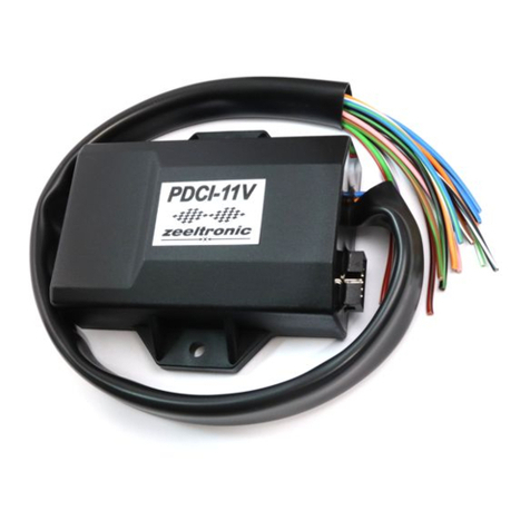
zeeltronic PDCI-11V User manual

zeeltronic

zeeltronic PDCI-11V User manual

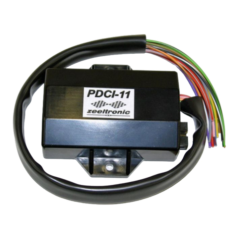
zeeltronic PDCI-11 User manual

zeeltronic

zeeltronic PDCI-11 User manual

zeeltronic PDCI-24VT Owner's manual

zeeltronic

zeeltronic PDCI-24VT Owner's manual

zeeltronic PCDI-10 User manual

zeeltronic

zeeltronic PCDI-10 User manual

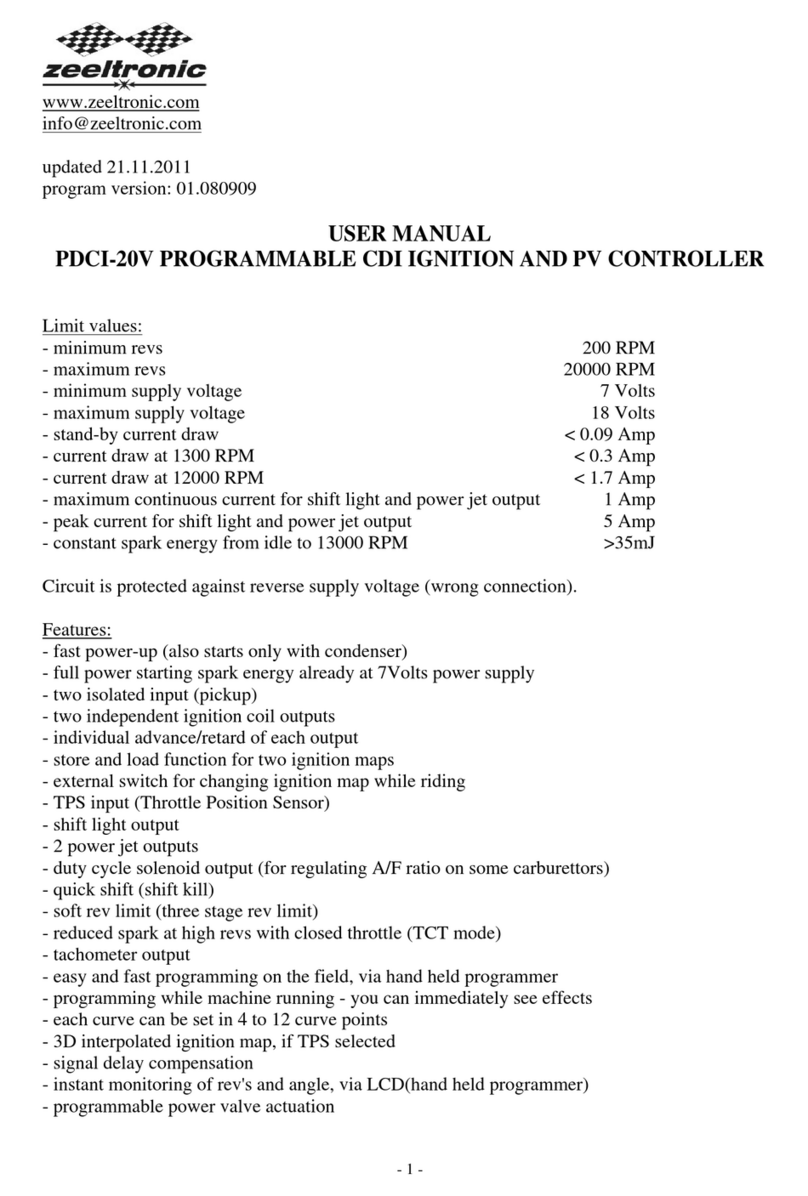
zeeltronic PDCI-20V User manual

zeeltronic

zeeltronic PDCI-20V User manual

zeeltronic PDCI-11V User manual

zeeltronic

zeeltronic PDCI-11V User manual

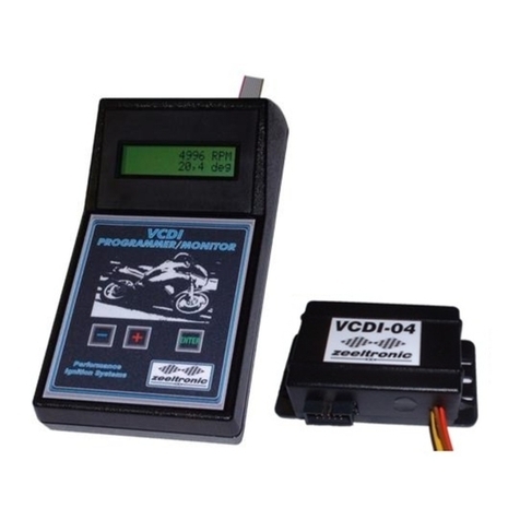
zeeltronic VCDI-04 User manual

zeeltronic

zeeltronic VCDI-04 User manual

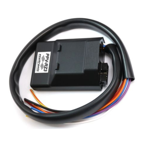
zeeltronic PPV-RZ3 User manual

zeeltronic

zeeltronic PPV-RZ3 User manual

zeeltronic PDCI-44V User manual

zeeltronic

zeeltronic PDCI-44V User manual

zeeltronic PSR-S01 User manual

zeeltronic

zeeltronic PSR-S01 User manual

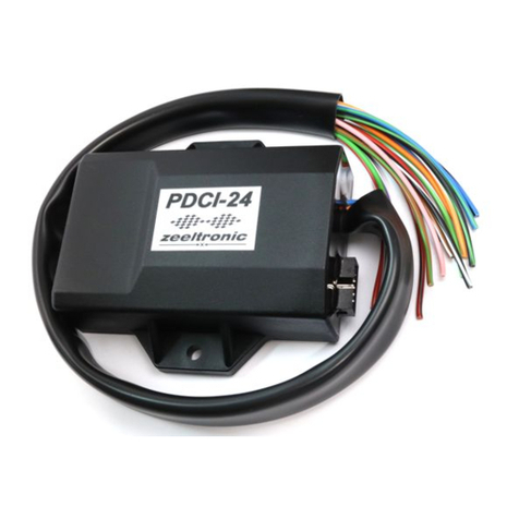
zeeltronic PDCI-24 User manual

zeeltronic

zeeltronic PDCI-24 User manual

zeeltronic PDCI-24V User manual

zeeltronic

zeeltronic PDCI-24V User manual

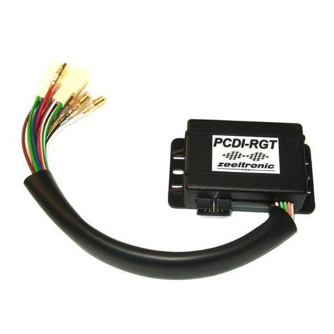
zeeltronic PCDI-RGT User manual

zeeltronic

zeeltronic PCDI-RGT User manual

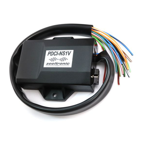
zeeltronic PDCI-NS1V User manual

zeeltronic

zeeltronic PDCI-NS1V User manual

zeeltronic PCDI-VE1 User manual

zeeltronic

zeeltronic PCDI-VE1 User manual

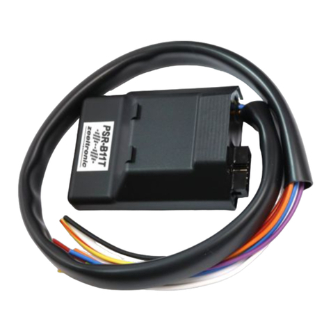
zeeltronic ZeelProg PSR-B11T Owner's manual

zeeltronic

zeeltronic ZeelProg PSR-B11T Owner's manual

Popular Controllers manuals by other brands

CDVI SASIC installation manual

CDVI

CDVI SASIC installation manual

Autonics TM2-22RB user manual

Autonics

Autonics TM2-22RB user manual

Siemens SIMOTION C operating instructions

Siemens

Siemens SIMOTION C operating instructions

iNels SA2-01B Manual instructions

iNels

iNels SA2-01B Manual instructions

Christie TVC-1211 user manual

Christie

Christie TVC-1211 user manual

SPECS CCX 70 user manual

SPECS

SPECS CCX 70 user manual

Honeywell ML4105 Product data

Honeywell

Honeywell ML4105 Product data

Dove Lighting Systems SceneMaster 8 user manual

Dove Lighting Systems

Dove Lighting Systems SceneMaster 8 user manual

Voicebird Voicebird Mini user guide

Voicebird

Voicebird Voicebird Mini user guide

Munters Farm Center Pro Manual for use and maintenance

Munters

Munters Farm Center Pro Manual for use and maintenance

Pakton JVA Z Series user manual

Pakton

Pakton JVA Z Series user manual

Actuator Systems TCR-40C Series Usage instructions

Actuator Systems

Actuator Systems TCR-40C Series Usage instructions

Amroad ID5101 user manual

Amroad

Amroad ID5101 user manual

METRON FD4 manual

METRON

METRON FD4 manual

Danfoss VLT FC Series Spare Brake IGBT installation instructions

Danfoss

Danfoss VLT FC Series Spare Brake IGBT installation instructions

Siemens SSC161.05UT manual

Siemens

Siemens SSC161.05UT manual

LEUCHTWURM 43LED/528-W manual

LEUCHTWURM

LEUCHTWURM 43LED/528-W manual

Honeywell HJK7000 UltraKey Plus Technical note

Honeywell

Honeywell HJK7000 UltraKey Plus Technical note

manuals.online logo
manuals.online logoBrands
  • About & Mission
  • Contact us
  • Privacy Policy
  • Terms and Conditions

Copyright 2025 Manuals.Online. All Rights Reserved.