Zehnder Group ComfoAir 160 User guide

ComfoAir 160
Installer manual

EN - II
All rights reserved.
This manual has been compiled with the utmost care. The publisher cannot be held liable for any damage caused as a result
of missing or incorrect information in this manual. In case of disputes the Dutch version of these instructions will be binding.

Table of Contents
Preface ............................................................................................................................................................ 1
1INTRODUCTION ............................................................................................................................................. 1
1.1 Warranty and liability .......................................................................................................................... 1
1.1.1 Guarantee conditions ................................................................................................................ 1
1.1.2 Liability ...................................................................................................................................... 1
1.2 Safety .................................................................................................................................................. 2
1.2.1 Safety regulations...................................................................................................................... 2
1.2.2 Safety provisions and measures ............................................................................................... 2
1.2.3 Pictograms used ....................................................................................................................... 2
2. FOR THE INSTALLER ..................................................................................................................................... 3
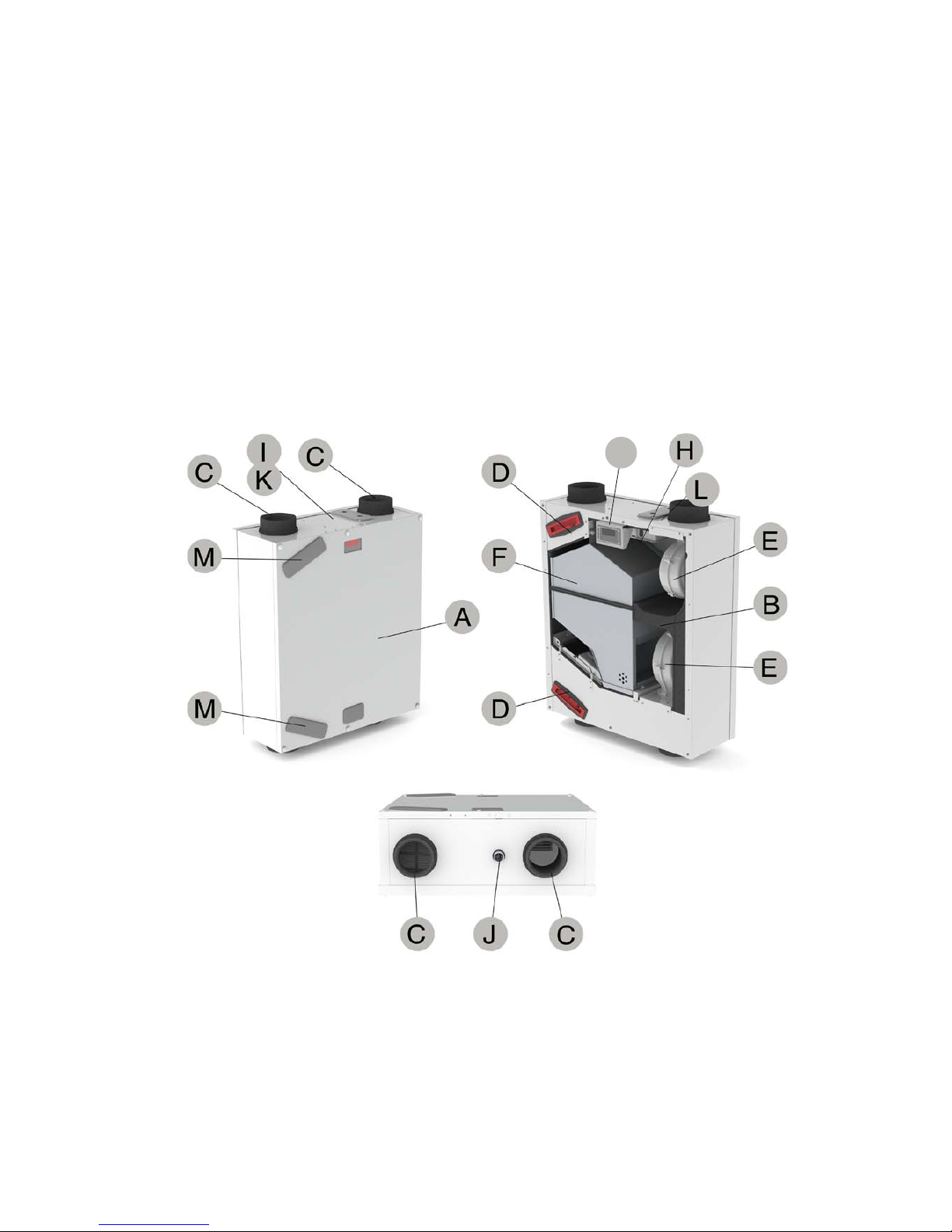
2.1 ComfoAirconguration...................................................................................................................... 3
2.2 Technicalspecications ..................................................................................................................... 4
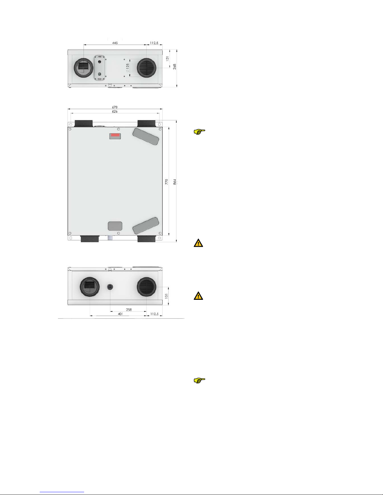
2.3 Dimension sketch ............................................................................................................................... 6
2.4 Installation conditions ........................................................................................................................ 6
2.5 Installation of the ComfoAir ............................................................................................................... 6
2.5.1 Transport and unpacking...........................................................................................................6
2.5.2 Checking the delivery ................................................................................................................ 6
2.5.3 Rework Right to Left version ..................................................................................................... 7
2.5.4 Connecting the power cord.......................................................................................................7
2.6 MountingoftheComfoAir.................................................................................................................. 7
2.6.1 Mounting on the ceiling ............................................................................................................ 7
2.6.2 Mounting on the wall ................................................................................................................. 8
2.6.3 Connection of the air ducts ....................................................................................................... 8
2.6.4 Connection of the condensation drain ......................................................................................9
2.7 CommissioningtheComfoAir............................................................................................................ 9
2.7.1 Display on the unit................................................................................................................... 10
2.7.2 CC Ease panel......................................................................................................................... 10
2.7.3 P menus for the user ............................................................................................................... 12
2.7.4 P menus for the installer.......................................................................................................... 14
2.8 Programmingairspecications ...................................................................................................... 17
2.9 Maintenance by the installer............................................................................................................ 18
2.9.1 Inspecting and cleaning the heat exchanger........................................................................... 18
2.9.2 Inspecting and cleaning the fans............................................................................................. 19
2.10 Malfunctions...................................................................................................................................... 19
2.10.1 Malfunction alerts on digital operating devices....................................................................... 19
2.10.2 3-position switches with malfunction indicator.......................................................................19
2.10.3 What to do in the event of a malfunction / Trouble shooting .................................................. 20
2.10.4 Malfunctions (or problems) without alerts .............................................................................. 26
2.11 Service parts...................................................................................................................................... 27
2.12 Wiringdiagram:ComfoAir160........................................................................................................ 28
2.13 EEC declaration of conformity ........................................................................................................ 29
III - EN


1 - EN
Preface
Carefully read this manual before use.
This manual provides all the information required for
safe and optimal installation and maintenance of the
ComfoAir 160. It is also intended as a reference for
servicing, so that this can be carried out in a respon-
sible manner. The device is subject to continuous de-
velopment and improvement. As a result, the Com-
foAir 160 may slightly differ from the descriptions.
NOTE
This manual has been compiled with
the utmost care. However, no rights can be
derived from it. In addition, we at all times
reserve the right to change the contents of
this manual, without prior notice.
1 Introduction
The device's name is ComfoAir 160. In the following
manual it will be referred to as ComfoAir.
The ComfoAir is a balanced ventilation system with
heat recovery in order to create healthy, balanced and
energy-efficient ventilation in houses. The ComfoAir
has a CE marking on the identification plate. The iden-
tification plate can be found on top of the ComfoAir.
1.1 Warranty and liability
1.1.1Guarantee conditions
The ComfoAir is covered by a manufacturer’s war-
ranty for a period of 24 months after fitting up to a
maximum of 30 months after the date of manufacture.
Warranty claims may only be submitted for material
faults and/or construction faults arising during the
warranty period. In the case of a warranty claim, the
ComfoAir must not be dismantled without written per-
mission from the manufacturer. Spare parts are only
covered by guarantee, if they were supplied by the
manufacturer and have been installed by an approved
installer.
The warranty becomes invalid if:
• The guarantee period has elapsed;
• The device is used without lters;
• Parts are used that have not been supplied by the
manufacturer;
• Non-authorised changes or modications have
been made to the unit.
1.1.2 Liability
The ComfoAir has been designed and manufactured
for use in balanced ventilation systems incorporating
Zehnder heat recovery systems. Any other application
is seen as inappropriate use and can result in dam-
age to the ComfoAir or personal injury, for which the
manufacturer cannot be held liable.
The manufacturer is not liable for any damage origi-
nating from:
• Non-compliance with the safety, operating and
maintenance instructions in this manual;
• The use of components not supplied or recom-
mended by the manufacturer.
Responsibility for the use of such components
lies entirely with the installer;
• Normal wear and tear.

EN - 2
1.2 Safety
1.2.1 Safetyregulations
Always comply with safety regulations in this manual.
Non-compliance with the safety regulations, warn-
ings, notes and instructions in this manual can cause
personal injury or damage to the ComfoAir.
• The ComfoAir may only be installed, connected,
rendered operational and maintained by an ap-
propriately approved installer, unless otherwise
indicated in this manual;
• Installation of the ComfoAir must be carried out
in accordance with the general and locally appli-
cable construction, safety and installation instruc-
tions of the local council, electricity and water
boards or other agencies;
• Observe the safety regulations, warnings, com-
ments and instructions as prescribed in this man-
ual at all times;
• Keep this manual with the ComfoAir throughout
its life;
• Instructions with regard to cleaning or replacing
the filters on the intake and exhaust valves must
be carefully observed;
• The specications stated in this document may
not be changed;
• The ComfoAir is only suitable for connetion to
230V 50Hz mains;
• It is recommended to take out a maintenance
contract so that the device is checked on a regu-
lar basis. The supplier can provide a list of regis-
tered installers nearby.
1.2.2 Safety provisions and measures
• The ComfoAir cannot be opened without using
tools;
• It should not be possible to touch the fans, there-
fore ducting must be connected to the ComfoAir
at a minimum duct length of 900mm.
1.2.3 Pictogramsused
The following pictograms are used in this manual:
Point of attention.
Risk of:
- damage to the device;
- performance of the device is compro-
mised if instructions are not observed
carefully.
Risk of personal injury to the user or installer.

3 - EN
2 For the Installer
2.1 ComfoAirconguration
The standard ComfoAir configuration consists of:
• External casing (A) of coated sheeting;
• Interior (B) of EPP;
• 4 connections of EPP (C) for the air ducts;
• 2 lters (D) for air purication; Type G4 for outside air and type G4 for return air;
• 2 energy-efcient DC motors (E) with high-efcient fan and constant volume;
• HE (High Efcient) heat exchanger (F);
• Connector panel (L) with connections for the CC-Ease, the enthalpy exchanger and the two 0 -10 V controls;
• Electronic box with PCB panel (H) with connections for the fans, the bypass temperature sensors (T1 to T4), the
3-position switch with or without malfunction and lter indication (optional) and the bathroom switch (optional);
• Identication plate (I) detailing information on the ComfoAir (not visible);
• Condensation drain (J) to drain the condensation of the warm return air;
• Sticker (K) detailing the air connections (not visible);
• Display (G) to read data, and for programming procedures;
• 2 Filtercaps (M);
• 2 Mounting brackets (not visible).
G

EN - 4
2.2 Technicalspecications
ComfoAir 160 nL (normal air volumes)
Position Ventilation capacity Power
Absent Setting 29 m3/h at 4 Pa 10 W
Low Setting 57 m3/h at 14 Pa 14 W
Medium Setting 77 m3/h at 27 Pa 19 W
High Setting 112 m3/h at 57 Pa 32 W
Maximum 157 m3/h at 110 Pa 67 W
Position Ventilation capacity Current
Absent Setting 29 m3/h at 4 Pa 0,08 A
Low Setting 57 m3/h at 14 Pa 0,11 A
Medium Setting 77 m3/h at 27 Pa 0,15 A
High Setting 112 m3/h at 57 Pa 0,25 A
Maximum 157 m3/h at 110 Pa 0,52 A
Electricity
Power supply 230/50 V/Hz
Cos.phi 0,52 - 0,56
Supply fan noise level (at 0 m)
Position Ventilation capacity Sound power
Absent Setting 29 m3/h at 4 Pa 42 dB(A)
Low Setting 57 m3/h at 14 Pa 49 dB(A)
Medium Setting 77 m3/h at 27 Pa 55 dB(A)
High Setting 112 m3/h at 57 Pa 62 dB(A)
Maximum 157 m3/h at 110 Pa 69 dB(A)
Exhaust fan noise level (at 0 m)
Position Ventilation capacity Sound power
Absent Setting 29 m3/h at 4 Pa 27 dB(A)
Low Setting 57 m3/h at 14 Pa 36 dB(A)
Medium Setting 77 m3/h at 27 Pa 45 dB(A)
High Setting 112 m3/h at 57 Pa 51 dB(A)
Maximum 157 m3/h at 110 Pa 52 dB(A)

5 - EN
ComfoAir160HL(highairvolumes)
Position Ventilation capacity Power
Absent Setting 29 m3/h at 4 Pa 10 W
Low Setting 66 m3/h at 19 Pa 16 W
Medium Setting 113 m3/h at 56 Pa 32 W
High Setting 144 m3/h at 93 Pa 56 W
Maximum 157 m3/h at 110 Pa 67 W
Position Ventilation capacity Current
Absent Setting 29 m3/h at 4 Pa 0,08 A
Low Setting 66 m3/h at 19 Pa 0,13 A
Medium Setting 113 m3/h at 56 Pa 0,25 A
High Setting 144 m3/h at 93 Pa 0,44 A
Maximum 157 m3/h at 110 Pa 0,52 A
Electricity
Power supply 230/50 V/Hz
Cos.phi 0,52 - 0,56
Supply fan noise level (at 0 m)
Position Ventilation capacity Sound power
Absent Setting 29 m3/h at 4 Pa 42 dB(A)
Low Setting 66 m3/h at 19 Pa 51 dB(A)
Medium Setting 113 m3/h at 56 Pa 62 dB(A)
High Setting 144 m3/h at 93 Pa 67 dB(A)
Maximum 157 m3/h at 110 Pa 69 dB(A)
Exhaust fan noise level (at 0 m)
Position Ventilation capacity Sound power
Absent Setting 29 m3/h at 4 Pa 27 dB(A)
Low Setting 66 m3/h at 19 Pa 36 dB(A)
Medium Setting 113 m3/h at 56 Pa 45 dB(A)
High Setting 144 m3/h at 93 Pa 51 dB(A)
Maximum 157 m3/h at 110 Pa 52 dB(A)
GeneralSpecications
HE Exchanger Material Polystyrene
Interior Material EPP
Material Enthalpy exchanger Polystyrene, Polyethylene + Polyether Copolymer
Thermal Yield 95%
Mass 28 kg

EN - 6
2.3 Dimension sketch 2.4 Installation conditions
In order to determine whether the ComfoAir can be
installed in a certain area, the following aspects must
be taken into account:
• The ComfoAir must be installed according to the
general and locally applicable safety and installa-
tion regulations of power and water companies, as
well as the instructions in this manual.
• The system must be tted to allow sufcient room
around the ComfoAir for the air connections and
supply and exhaust ducts as well as for carrying
out maintenance activities.
•
T
he ComfoAir must be installed in a frost-free space.
The condensation must be drained off frost-free, at a
gradient and incorporate a 'U' bend.
Condensation may form on the outside of
the ComfoAir if the unit is tted in a space
with higher average humidity levels (such as
a bathroom, shower, toilet or kitchen). This is
not a problem for the ComfoAir.
• The room must offer the following provisions:
- Air duct connections.
- 230V electrical connection.
- Provisions for the condensation drain.
- Wiring for an wired 3-position switch
(optional).
• The cable used to connect the CC Ease panel
must have the following specifications:
- Cable type: shielded twisted pair 4x0.34mm2.
- Cable length: 10m maximum.
The connections of the CC Ease panel must
be crossed. (Rx must be connected to Tx).
• A gap should be left near the doors in order to
ensure effective and draughtfree airflow in the
house. A gap under the inside doors must be at
least 10mm.
If these openings are obstructed, due to
draught excluders or deep-pile carpet, the
airow in the house will stagnate. As a result,
system performance will be compromised or
fail altogether.
2.5 Installation of the ComfoAir
2.5.1 Transportandunpacking
Take the necessary precautions when transporting
and unpacking the ComfoAir.
Make sure the packing material is disposed
of in an environmentally friendly manner.
2.5.2Checkingthedelivery
Contact your supplier immediately in case of damage
or an incomplete delivery. The delivery must include:
• ComfoAir with 2 mounting brackets installed.
Check the identification plate to ensure that it is
the required type;
• Documentation.

7 - EN
The ComfoAir is supplied in the following types:
Type
ComfoAir 160 Basic R
ComfoAir 160 Basic R ERV
ComfoAir 160 R Luxe
ComfoAir 160 R Luxe ERV
Meaning of the suffixes:
* R = Right version
* ERV = Contains a enthalpy exchanger by default.
CC Ease panel (optional) can be ordered separately.
2.5.3ReworkRighttoLeftversion
1. Remove the front panel by first removing the 6 protective
caps (A) then the screws.
2. Remove the protection cap in the bottom of the front panel
(B).
3. Place the removed protection cap in the old display hole.
4. Push out the foam behind the new gap and place it behind
the moved protection cap.
A
A
B
5. Release the back panel and the mounting brackets by un-
screwing the 4 screws.
6. Remove the cover of the electronic box by pressing in the
2 click connectors (C).
7. Remove the display connector from the control PCB.
8. Release the display by unscrewing the 2 screws (D)
9. Place the removed display on the back side of the Com-
foAir.
10. Connect the display connector again.
11. Place the cover of the electronic box back.
12. Remove the 2 filters (E) from the ComfoAir.
13. Place the back panel and the mounting brackets on the
old front side.
14. Place the removed filters in the new front side of the Com-
foAir.
15. Place the front panel on the old back side.
2.5.4Connectingthepowercord
1. Release the electronic cover by unscrewing the 4 screws
(F).
2. Carefully pull up the electronic cover
3. Pull the power cord thru the hole marked "230V".
4. Connect the Blue wire to the connector marked "N".
5. When present connect the Brown wire to the connector
marked "H".
6. When present connect the Black wire to the connector
marked "M".
7. Connect the Gray wire to the connector marked "L".
8. Connect the Green/Yellow wire to the connector marked
""
Make sure the earth wire (Green/Yellow) is at
least 40 mm longer than the other connected
wires.
9. Carefully place the electronic cover back.
10 Fasten the electronic cover with the 4 removed screws.
2.6 MountingoftheComfoAir
The ComfoAir can be mounted two ways:
• On the ceiling;
• On the wall.
2.6.1 Mountingontheceiling
804
C
2%
Mount the ComfoAir to a ceiling with a minimum mass
of at least 200 kg/m2.
1. Seal off the existing condensation drain.
2. Remove the front panel by first removing the 6
protective caps (A) then the screws.
A

EN - 8
3. Remove the metal cover at the lower edge behind
the front panel by removing the two screws.
4. Remove the pre-punched section for the conden-
sation drain from the foam in the front panel.
5. Remove the aluminium tape (B).
6. Fit the special at condensation drain (1 screw in
the centre) over the holes in the exchanger. The
flat condensation drain is available on request
from Zehnder.
7. Refit the front panel.
8. Mark the position of the mounting points on the
ceiling.
Allow a 2% run-off to the condensation drain
(C).
9. Fix the ComfoAir to the ceiling.
10. Fit the condensation drain to the new connector.
Ensure that there is enough room under the ComfoAir
for carrying out maintenance. The ComfoAir does not
require any space at the sides for effective operation.
Do not mount the side of the ComfoAir against
the wall due to the risk of impact sound.
2.6.2 Mountingonthewall
626
804
Mount the ComfoAir against a wall with a minimum
mass of 200 kg/m2.
1. Using a spirit level, fix the mounting bracket hori-
zontally to the wall. Make sure there is enough
space under the ComfoAir to mount the siphon.
2. Mount the ComfoAir on the wall.
3. Mount the condensation drain under the Com-
foAir.
Make sure to leave a minimum space of 1 metre in
front of the ComfoAir for carrying out maintenance.
The ComfoAir does not require any space at the sides
for effective operation.
Do not mount the side of the ComfoAir against
the wall due to the risk of impact sound.
2.6.3 Connection of the air ducts
The following aspects must be taken into account,
while installing the air ducts:
• Install the air exhaust duct so it drains in the di-
rection of the ComfoAir.
• Insulate the internal ductwork for the outside
air supply and the air exhaust duct to render the
ComfoAir damp proof. This prevents the forma-
tion of condensation on the outside of the ducts.
• To prevent unnecessary temperature loss in either
the summer or the winter, we recommend fitting
thermal and damp-proof insulation to the supply
ducts from the ComfoAir up to the supply valves.
• Install the air ducts with a minimum ø of 125 mm,
as little air resistance as possible and free from air
leakage.

9 - EN
• Install a silencer of at least 1m straight directly
onto the supply and return air connections. For
relevant advice, please contact Zehnder.
• When using exible ducting only Zehnder
ducting
systems may be used. Any other flexible ducting
will disturb the basic operating principle of the bal-
anced ventilation system.
•
We recommend that the ventilation system is fitted
with intake and exhaust valves made by Zehnder.
ComfoAir 160 - Right
2.6.4 Connection of the condensation drain
Standard heat exchanger
ComfoAir - Right
Warm exhaust air is cooled by the outside air in the
heat exchanger. This causes the moisture in the in-
door air to condense in the heat exchanger. The con-
densation water created in the heat exchanger is fed
to a PVC condensation drain.
The connection for the condensation drain has an ex-
ternal diameter of 32 mm. It is located underneath the
ComfoAir.
• Connect the condensation drain, via a pipe with
coupling or hose, to the water seal (siphon) of the
domestic waste-water system.
• Make sure that the outer end of the pipe or tube
exits is at least 60mm below the water level.
• Ensure the condensation drain pipe on ceiling-
mounted units has a run-off to the U bend. of at
least 2%.
Ensure that the water seal connected to the
domestic waste-water system is always full
of water. This prevents the ComfoAir from
sucking in any leakage air.
Enthalpy exchanger
When the ComfoAir is fitted with an enthalpy exchanger
the humidity from the extracted air is partly transferred
to the fresh supply air. In this case you delay the process
of drying out the house in dry winter months, additionally
there is no condensate that must be drained from the
ComfoAir. Therefore a condensation drain is not neces-
sary with an enthalpy exchanger.
Ensure that the condensation drain is sealed.
This prevents the ComfoAir from sucking in
any leakage air.
The condensation drain can be sealed with a standard
screw-cap.
2.7 CommissioningtheComfoAir
After installation, the ComfoAir must be commis-
sioned.
This can be done via the P menus on the digital op-
erating device. These P menus can be used to enter
various settings (ventilation programmes, in particu-
lar) for the ComfoAir. An overview of the available P
menus is given below:
Menu Options
P1 Reading statuses (from menu P2)
P2 Setting time delays
P3 Setting and reading the ventilation levels
P4 Setting and reading the temperatures
P5 Setting additional programmes
P6 Setting additional programmes
P7 Reading and resetting malfunctions (and
system information)
P8 Setting the RF input
P9 Reading statuses (from menu P5 and P6)
P menus P1, P2 and P9 can be accessed by the user,
mainly to read statuses and set time delays. The re-
maining P menus P3 to P8 are intended solely for the
installer.
After a power cut, the bypass valve will au-
tomatically search for the correct position. It
may be that the valves move a few times so
the correct position can be determined.

EN - 10
2.7.1 Display on the unit
The ComfoAir can be operated and commissioned by
means of a display. The display is a digital operating
device which is mounted on the ComfoAir.
select menu up
OK down
supply off supply on
(led green) (led green)
comfort temperature
Shown in display
Ventilation setting absent
Ventilation setting low
Ventilation setting medium
Ventilation setting high
Menu symbol
Malfunction code (flashes)
Bypass
Access to the menus
Sequence Press Display Description
1MENU P2 Time delay
2s + ▼
(3 seconds)
P3 Press the buttons
simultaneously.
3sP4 Temperatures
4sP5 Settings
5sP6 Settings
6sP7 Malfunction / Reset /
Self-test
7sP8 0 - 10V Inputs
8sP9 Status
Example
Setting the MEDIUM POSITION of the supply fan to
40%.
Sequence Press Display Description
1MENU P2 Time delay
2s + ▼
(3 seconds) P3 Press the buttons
simultaneously.
3OK P30 Exhaust fan
Position A
4s (6x) P36 Select P36
5OK 50 Current setting
6▼ (10 x or press
continuously) 40 Select 40
7OK P36 Value is 40
8MENU P3
9MENU 1Fan setting
Some P menus (such as P1 and P9) can only
be read.
LeavingReadingmenu
• At action point 6 press "MENU" (instead of "OK").
The display can not be used for setting the
ventilation positions of the ComfoAir. The
arrowkeys are only for setting the additional
programmes.
2.7.2 CC Ease panel
The ComfoAir can be operated and commissioned
by means of a CC Ease panel, which can be ordered
separately. The CC (Comfort Control) Ease panel is
a digital operating device which can be mounted on
the wall in the living room and from there communi-
cates with the ComfoAir.
AccessingthePmenus
1. Press and hold " " and " " for 2 seconds,
simultaneously.
- Wait until "P 2" appears on the display.
P menus P1, P2 and P9 can now be ac-
cessed.
2. Press and hold " " and " " for 2 seconds,
simultaneously.
- Wait until P menu ”P3" appears on the
display.
P menus P3 to P8 can now be accessed.
3. Select the desired P menu, e.g. " 5 ", using "
" or " ".
1
A
2
3
X X
X X
•
1
A
2
3
X X
X X
•
1
A
2
3
X X
X X
•
1
A
2
3
X X
X X
•
1
A
2
3
X X
X X
•
OK
MENU
·
·
·
OK
MENU
·
·
·
OK
MENU
·
·
·
OK
MENU
·
·
·
OK
MENU
·
·
·
1
A
2
3
X X
X X
•
1
A
2
3
X X
X X
•

11 - EN
4. Press " ".
5. Select the desired P sub-menu, e.g. " 51 ", using
" " or " ".
6. Press " ".
Entering settings in P menus
The minimum and maximum values for the
available settings parameters are preset in
the software.
7. Select a value for the parameter using " " or
" ".
8. Press " " to store the settings.
9. Repeat steps 5 to 8 to set multiple parameters in
succession.
Or
Press " " to return to the P menu so steps 3
to 8 can be repeated.
10. Press " " twice to return to the main screen.
Some P menus (such as P1 and P9) can only
be read.
LeavingReadingmenu
• Press " " (instead of " " ad step 8)

EN - 12
2.7.3 P menus for the user
Menu P1 ¨Status of programmes
Status
Sub-
menu Description Activated
P11 Is menu 21 currently active? Yes (1) / No (0)
P12 Is menu 22 currently active? Yes (1) / No (0)
P13 Is menu 23 currently active? Yes (1) / No (0)
P14 Is menu 24 currently active? Yes (1) / No (0)
P15 Is menu 25 currently active? Yes (1) / No (0)
P16 Is menu 26 currently active? Yes (1) / No (0)
Menu P2 ¨Setting time delays
Time delay values
Sub-menu Description Mini-
mum
Maxi-
mum
General
Reset
P21
(Optional)
Note:
Only applies to systems
ttedwithacordedswitch
and a second switch in the
bathroom.
Delay timer for the bathroom switch (to switch
to high position).
• 'x' minutes after operating the bathroom
switch, the ComfoAir switches to the high
setting.
- Low voltage input
0 Min. 15 Min. 0 Min.
P22
(Optional)
Note:
Only applies to systems
ttedwithacordedswitch
and a second switch in the
bathroom.
Overrun timer for the bathroom switch (to
switch to normal position).
• 'x' minutes after operating the bathroom
switch, the ComfoAir switches back to the
normal setting.
- Low voltage input
0 Min. 120 Min. 30 Min.
P23
(Optional)
Note:
Only applies to systems
ttedwithahardwired
3-position switch.
Overrun timer for ventilation position 3 (using
a wired 3-position switch).
• If ventilation setting 3 (high) is switched on
briefly (< 3 sec), the ComfoAir will switch
to the high setting for 'x' minutes and then
automatically returns to the normal setting.
If any 3-position switch is operated during this
lagging time the ComfoAir will instantly revert
to the ventilation position as set at that time.
0 Min. 120 Min. 0 Min.
P24 Filter warning
• 'x' weeks after cleaning the lters the "fil-
ter dirty" alert will reappear.
10 weeks 26 weeks 16
weeks
P25
Note:
Onlyappliestosystemst-
ted with an RF switch.
Overrun timer for ventilation setting 3 (using "
").
• After pressing " " briefly (< 2 sec.), the
ComfoAir will switch to the high setting for
‘x’ minutes and then automatically returns
to the normal setting.
If any 3-position switch is operated during this
lagging time the ComfoAir will instantly revert
to the ventilation position as set at that time.
1 Min. 20 Min. 10 Min.

13 - EN
Time delay values
Sub-menu Description Mini-
mum
Maxi-
mum
General
Reset
P26
Note:
Onlyappliestosystemst-
ted with an RF switch.
Overrun timer for ventilation setting 3 " using
".
• After pressing " " continuously (> 2 sec.),
the ComfoAir will switch to the high setting
for ‘x’ minutes and then automatically re-
turns to the normal setting.
If any 3-position switch is operated during this
lagging time the ComfoAir will instantly revert
to the ventilation position as set at that time.
1 Min. 120 Min. 30 Min.
P27
Note:
Onlyappliestosystemst-
ted with a CC Ease panel.
Timer for the Boost setting.
• After pressing “ ” continuously (>2 sec.)
on the CC Ease panel, the ComfoAir will
switch to the high setting for 'x' minutes
and then automatically returns to the NOR-
MAL setting
If any 3-position switch is operated during this
lagging time the ComfoAir will instantly revert
to the ventilation position as set at that time.
0 Min. 120 Min. 30 Min.
Menu P9 ¨Status of programmes (from menu P5 and P6 additional programmes)
Status
Sub-menu Description Activated
P90 Open re programme active? Yes (1) / No (0)
P91 Bypass Open? Yes (1) / No (0)
P94 n/a Yes (1) / No (0)
P95 Frost protection active? Yes (1) / No (0)
P97 Enthalpy programme active? Yes (1) / No (0)

EN - 14
2.7.4 P menus for the installer
Menus with a dash in 'Minimum' and 'Maximum' value are Reading menus.
Menu P3 ¨Setting ventilation programmes
Ventilationprogrammevalues
Submenu Description Minimum Maximum General
Reset
P30 Setting the capacity (in %) of the
exhaust fan in absent position.
0% or 15% 97% nL / HL
15% / 15%
P31 Setting the capacity (in %) of the
exhaust fan in low position.
16% 98% nL / HL
35% / 40%
P32 Setting the capacity (in %) of the
exhaust fan in medium position.
17% 99% nL / HL
50% / 70%
P33 Setting the capacity (in %) of the
exhaust fan to high position.
18% 100% nL / HL
70% / 90%
P34 Setting the capacity (in %) of the
supply fan to absent position.
0% or 15% 97% nL / HL
15% / 15%
P35 Setting the capacity (in %) of the
supply fan in low position.
16% 98% nL / HL
35% / 40%
P36 Setting the capacity (in %) of the
supply fan in medium position.
17% 99% nL / HL
50% / 70%
P37 Setting the capacity (in %) of the
supply fan in high position.
18% 100% nL / HL
70% / 90%
P38 Current capacity (in %) of the
exhaust fan.
- - Current %
P39 Current capacity (in %) of the
supply fan.
- - Current %
Menu P4 ¨Reading the temperatures
Temperature values
Submenu Description Minimum Maximum General
Reset
P41 Comfort temperature 12 oC 28 oC 20 oC
P45 Current value of T1
(= outside air temperature)
- - Current oC
P46 Current value of T2
(= supply air temperature)
- - Current oC
P47 Current value of T3
(= return air temperature)
- - Current oC
P48 Current value of T4
(= exhaust air temperature)
- - Current oC

15 - EN
Additionalprogrammevalues
Submenu Description Minimum Maximum General
Reset
P56 Setting the required air volume in the house.
• nL: ”normal air volume”.
• HL: "high air volume".
nL HL HL
Setting the air volume is the starting point for programming the air specications and set-
ting the fans.
P58 Enter controller priorities.
• 0; The highest air setting is leading INCLUDING the sig-
nals from the analogue inputs
• 1; The highest air setting is leading EXCLUDING the
signals from the analogue inputs
0 1 0
P59 Confirming the presence of an enthalpy exchanger.
• 0; Enthalpy exchanger not tted
• 1; Enthalpy exchanger with enthalpy sensor.
• 2; Enthalpy exchanger without enthalpy sensor.
0 (= No) 2 (= Yes) 0
Ensure the condensation drain is sealed.
If an enthalpy exchanger without a sensor is selected, then the safety programme will not
be activated and malfunction alerts EA1 & EA2 will never occur.
Menu P5 ¨Setting additional programmes
Additionalprogrammevalues
Submenu Description Minimum Maximum General
Reset
P50 Activation of the open fire programme. 0 (= No) 1 (= Yes) 0
P51 n/a 0 (= No) 1 (= Yes) 0
Leave the value at '0'.
P52 n/a 0 3 2

EN - 16
Menu P7 ¨Reading malfunctions (and system information)
(Malfunction) information values
Submenu Description Minimum Maximum General
Reset
P75 General reset.
• Press "OK" on the display or press
“” on the CC-Ease panel for at
least 5 seconds to carry out a general
reset.
All original software settings are re-
stored following a general reset.
0 1
(= activate)
0
Note:
After a general reset, the ComfoAir will ask you to reset the “nL / HL” (see P56) settings.
Following a general reset, all settings and programmes need to be checked and set to the
right value.
P76 Self-testing the ComfoAir 0 1
(= activate)
0
• TheLED'sonthedisplaywillstartblinking.
• TheComfoAirwillrunatmaximumRotationPerMinute(RPM).
• Thebypassvalvewillopenandclose.
P77 Resetting filter dirty counter 0 1
(= activate)
0
Note:
This resets the counter that triggers a dirty filter alert on the ComfoAir. This allows the filter to be cleaned or
replaced when the dirty filter alert appears.
Menu P8 ¨Setting the RF input and digital inputs (0-10V)
Analogueinputvalues
Submenu Description Minimum Maximum General Reset
810 Analogue input 1 0= not fitted 1= fitted 0 1 0
811 0= controlling 1= programming (analogue input 1) 0 1 0
812 set point analogue input 1 (programming) 0 100 50
813 min. setting analogue input 1 0 99 0
814 max. setting analogue input 1 0 100 100
815 0=positive analogue input 1 1=negative setting ana-
logue input 1
010
816 read-out analogue input 1 0 100 -
820 Analogue input 2 0= not fitted 1= fitted 0 1 0
821 0= controlling 1= programming (analogue input 2) 0 1 0
822 set point analogue input 2 (programming) 0 100 50
823 min. setting analogue input 2 0 99 0
824 max. setting analogue input 2 0 100 100
825 0=positive analogue input 2 1=negative setting ana-
logue input 2
010
826 read-out analogue input 2 0 100 -
850 RF input 1 0= not tted 1= tted 0 1 0
851 0= controlling 1= programming (RF input 1) 0 1 0
852 set point RF input 1 (programming) 0 100 50
853 min. setting RF input 1 0 99 0
854 max. setting RF input 1 0 100 100
855 0=positive RF input 1 1=negative setting RF input 1 0 1 0
856 Read-out RF input 0 100 -
Table of contents