Zehnder Rittling ComfoSense CH User manual

andleiding ComfoSense
Manual ComfoSense
Betriebsanleitung ComfoSense
Manuel ComfoSense
Manuale ComfoSense
Podręcznik ComfoSense
Manual ComfoSense
eating Cooling Fresh Air Clean Air
omfoSense H
omfoSense 55 omfoSense 67

16 - EN
Table of contents
1 Introduction ......................................................................................... 17
1.1 Warranty ..................................................................................... 17
1.2 Safety .......................................................................................... 17
2 Use of the ComfoSense ...................................................................... 18
2.1 AUTO operation ........................................................................... 19
2.2 MAN operation ............................................................................ 19
2.3 Menu access ............................................................................... 20
2.4 Switching the omfoHood .......................................................... 20
2.5 Switching the omfoHood Timer ................................................. 20
2.6 Switching the PARTY TIMER ....................................................... 20
2.7 Ventilation program (PROG)......................................................... 21
2.8 Setting the LO K ...................................................................... 23
2.9
Setting the OMF ( omfort temperature) ......................................... 23
2.10 Switching the FAN ...................................................................... 23
2.11 Setting PARAM (Parameters) ....................................................... 24
2.12 LO K Back-up .......................................................................... 24
3. Error messages ...................................................................................25
4. Installation...........................................................................................26
5. Commissioning ...................................................................................26
5.1 Power up ...................................................................................... 26
5.2 Setting P-menu’s ......................................................................... 26
I. Figures .................................................................................................95

EN - 17
1 Introduction
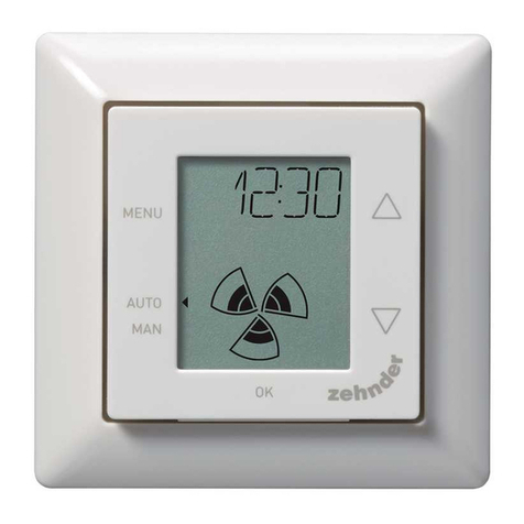
The omfoSense (henceforth called
“device”) is a control device for residential
ventilation units (henceforth called
“ventilation unit” or “HRU”). The device
can be used for the omfoAir Luxe,
omfoD Luxe, WHR Luxe, WHR plus, G90
and Santos Standard.
The device is designed for the following
purposes:
1. To set a ventilation program for the
ventilation unit (auto);
2. To set the ventilation volume of the
ventilation unit (manual);
3. To set the parameters of the
ventilation unit (P menus).
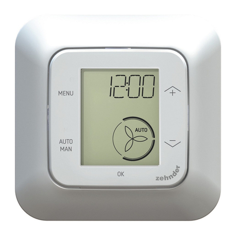
There are 3 different variations of the
device (as shown on the front page):
omfoSense 55, 67 and H.
With these 3 variations the device can be
built-in in almost every standard frame.
In addition, the omfoSense 67 is also
available with a wall-mounting casing.
Applicable pictograms
Point to watch.
Risk of:
- Damage to the device;
- Performance of the
ventilation unit is
compromised if instructions
are not observed carefully.
Questions
Please contact the supplier if you have any
questions. In the back of this document is
a list with the contact details of the main
suppliers.
1.1 Warranty
The manufacturer provides warranty for a
period of 24 months after installation to a
maximum of 30 months after production
date of the device.
The warranty becomes invalid if:
Q The installation has not been carried
out according to the applicable
regulations;
Q The defects are due to incorrect
connection, inexpert use or
contamination of the device;
Q Parts are used that have not been
supplied by the manufacturer or
repairs are made by unauthorized
persons.
On-site dismantling and assembly costs
are not covered by the terms of the
warranty. This also applies to normal wear
and tear. The manufacturer retains the
right to change the construction and/or
configuration of its products at any time
without being obliged to alter previously
delivered products.
1.2 Safety
Electrical dangers
There is a risk of electric shock during
installation or maintenance.
Always comply with safety regulations in
this document. Non-compliance with the
safety regulations, warnings, notes and
instructions in this document can cause
personal injury or damage to the device.
Disconnect the ventilation unit from the
main power before opening the housing of
the device.
Electrostatic discharge (ESD)
There is a risk that P Bs may be
damaged by an electrostatic discharge if
the electronics have to be replaced. For
this reason, always take ESD-inhibiting
measures when dealing with P Bs, such
as wearing an antistatic wristband.
18 - EN
2 Use of the ComfoSense
A
3
B
4
9
D
E
8
1 2
C
7 6
5
Buttons:
AQ Increase value;
Q Select next item.
BQ Decrease value;
Q Select previous item.
Q Shift;
Q onfirm.
DQ Automatic operation;
Q Manual operation.
EQ Enter menu;
Q Exit menu.
Display:
1Q Text;
Q Time.
2Value (program, parameter,
temperature).
3Q Degree elsius/Fahrenheit**;
Q Percentage.
4 omfoHood*.
5Q Supply fan off;
Q Exhaust fan off;
6 Fan speed.
7 Night cooling active.
8External sensor* overrules the
ventilation setting.
9Q Start time of a program;
Q End time of a program.
* Only available if the mentioned
function is connected.
** Shown temperature in °F will be
changed in steps of 2 degrees.

EN - 19
Meaning symbols:
1 SHIFT The second function of
the buttons is active.
1 TIMER
The ventilation setting
is overruled by a timer
function.
4omfoHood* is active.
5Supply fan is switched
off.
5Exhaust fan is switched
off.
6High fan speed.
6Medium fan speed.
6Low fan speed.
6
Fan is running at very
low speed.
(Only choose this option
when nobody is home.)
7Night cooling is active.
D
Q Manual operation
indicator;
Q Auto operation
indicator.
2.1 AUTO operation
In Automatic operation mode the device
can tell the ventilation unit automatically
which ventilation setting is wanted. The
default ventilation setting of the ventilation
unit is “Medium” (position 2). Eight
exceptions to this default setting can be
programmed into the device (see: Setting
the PROG).
The device is in Automatic operation mode
when is pointing to AUTO.
Press AUTO MAN, to switch to the
Automatic operation mode.
2.2 MAN operation
In Manual operation mode the
preprogrammed ventilation settings of the
device will be overruled (temporarily).
Overrule temporarily:
Directly press or to increase or
decrease the fan speed.
The manual operation mode overrules the
current program.
The is blinking next to MAN.
The next program will overrule the manual
operation mode again.
Press AUTO MAN to return to the
Automatic operation mode immediately.
Overrule permanently:
1. Press AUTO MAN, to go to Manual
mode.
2. Press or to increase or
decrease the fan speed.
The is pointing to MAN.
The device will stay in the Manual
operation mode until AUTO MAN is
pressed again.
* Only available if the mentioned
function is connected.

20 - EN
2.3 Menu access
Entering User menu
To enter the User menu, press MENU.
In the User menu, you can choose the
following options: HOOD*, TIMER HOOD*,
PARTY TIMER*, PROG, LO K and
BA K.
Leaving a menu
To go back to the previous menu level:
1. Press or to choose BA K.
2. Press OK to confirm.
To immediately go back to the main screen
press MENU.
When no buttons are used for an extended
period of time the device will automatically
return to the main screen.
Entering Expert menu
To enter the Expert menu:
1. Press OK. The text says SHIFT for 2
seconds.
2. Press MENU before the text SHIFT
disappears. The text says OMF.
In the Expert menu, you can choose the
following options: OMF, FAN, PARAM
and BA K.
2.4 Switching the
Comfo ood
This function is only visible if a omfoHood
(cooker hood with sensor) is connected.
Turning on the Comfo ood
1. Press MENU. The text says HOOD.
2. Press OK to confirm. The text says
ON for 2 seconds.
is visible in the main screen.
Turning off the Comfo ood
1. Press MENU. The text says HOOD.
2. Press OK to confirm. The text says
OFF for 2 seconds.
2.5 Switching the
Comfo ood Timer
This function is only visible if a omfoHood
(cooker hood with sensor) is connected
and a delay time is programmed in PARAM
P20.
Turning on the Comfo ood Timer
1. Press MENU. The text says HOOD.
2. Press to choose HOOD, TIMER.
3. Press OK to confirm. The text says
ON for 2 seconds.
The text TIMER is visible in the main
screen.
Turning off the Comfo ood Timer
The omfoHood Timer will automatically
turn off after the set time in PARAM P20.
Press or to turn the omfoHood
TIMER off immediately.
2.6 Switching the PARTY
TIMER
The ventilation setting can be increased
for a pre-set time. This can be useful when
additional ventilation is needed for a short
time.
Turning on the PARTY TIMER
This function is only visible if a delay time
is programmed in PARAM P27.
1. Press MENU. The text says HOOD or
PARTY, TIMER.
2. When the text says HOOD press
or to choose PARTY, TIMER.
3. Press OK to confirm. The text says
ON for 2 seconds. After this the text
says TIMER.
Turning off the PARTY TIMER
The PARTY TIMER will automatically turn
off after the set time in PARAM P27.
Press or to turn the PARTY TIMER
off immediately.
* Only available if the mentioned
function is connected.

EN - 21
2.7 Ventilation program (PROG)
Example:
Prog # Activity Day period Time Fan speed
Prog 1 Showering MO-FR 7:00 – 8:00
Prog 2 Not at home MO-FR 9:00 – 17:00
Prog 3 Making Lunch MO-FR 12:30 – 13:00
Prog 4 Breakfast WEEK 6:00 – 10:00
Prog 5 Lunch MO-FR 12:00 – 14:00
Programs can overlap each other. The
shortest program will always be the
leading program and overrule any longer
program.
The program with the least days will be the
leading program. In the example above,
Prog 1 overrules Prog 4.
When there are programs with the same
number of days, the program with the
shortest time is the leading program. In the
example above, Prog 3 overrules Prog 2.
When both overlapping programs have
an equally long period, the program with
the smallest program number will be the
leading program. In the example above,
Prog 3 overrules Prog 5.
Every day in the program starts
at 3:00 and ends at 2:59.
Setting a program
1. Press MENU.
2. Press or to choose PROG.
3. Press OK to confirm. SET is blinking.
The program number is visible.
Up to 8 programs can be
programmed. When all 8
programs are programmed the
text PROG 8 will be displayed
instead of SET.
4. Optional: Use or to choose
and change a previously set
program. PROG is blinking. The
program number is visible.
5. Press OK to confirm. The day period
indicator is blinking.

22 - EN
6. Press or to choose the day
period. The following day period can
be chosen:
Q MON = Monday;
Q TUE = Tuesday;
Q WED = Wednesday;
Q THU = Thursday;
Q FRI = Friday;
Q SAT = Saturday;
Q SUN = Sunday;
Q MO – FR = Mondays to Fridays;
Q SA – SU = Saturdays and
Sundays;
Q WEEK = Every day of the
week.
7. Press OK to confirm. START will
appear. The hour indicator is
blinking.
8. Press or to choose the hour.
9. Press OK to confirm. The minute
indicator is blinking.
10. Press or to choose the
minutes.
11. Press OK to confirm. END will
appear. The hour indicator is
blinking.
12. Press or to choose the hour.
13. Press OK to confirm. The minute
indicator is blinking.
14. Press or to choose the
minutes.
15. Press OK to confirm. The text says
SET. The fan speed indicator is
blinking.
16. Press or to choose the fan
speed. The following fan speeds can
be chosen:
Q AWAY = Very low;
Q LOW = Low;
Q MED = Medium;
Q HIGH = High;
17. Press OK to confirm. The text says
SAVED for 2 seconds. After this SET
is blinking. The next program number
is visible.
18. Press MENU to return to the main
menu.
Or go back to step 4 to set another
program.
Deleting a program
1. Press MENU.
2. Press or to choose PROG.
3. Press OK to confirm. SET is blinking.
The program number is visible.
4. Press or to choose the
program to delete. PROG is blinking.
The program number is visible.
5. Press OK seven times without
changing anything. The text says
BA K.
6. Press or to choose DEL.
7. Press OK to confirm. The text says
DONE for 2 seconds. SET is blinking.
The next program number is visible.
8. Press MENU to return to the main
menu.
Or go back to step 4 to delete
another program.
The numbering of the programs
will always be sequential.
Programs with a higher number
will shift back one place to fill
the gap of the deleted program.
Show current running program
1. Press OK. The text says SHIFT for 2
seconds.
2. Press AUTO MAN before the text
SHIFT disappears. The text says
NOW and displays the leading
program number below the text.
When no week program is active
two lines are displayed instead of a
program number.

EN - 23
2.8 Setting the CLOCK
1. Press MENU.
2. Press or to choose LO K.
3. Press OK to confirm. The day
indicator is blinking.
4. Press or to choose the day.
The following days can be chosen:
Q MON = Monday;
Q TUE = Tuesday;
Q WED = Wednesday;
Q THU = Thursday;
Q FRI = Friday;
Q SAT = Saturday;
Q SUN = Sunday.
5. Press OK to confirm. The hour
indicator is blinking.
6. Press or to choose the hour.
7. Press OK to confirm. The minute
indicator is blinking.
8. Press or to choose the
minutes.
9. Press OK to confirm. The text says
SAVED for 2 seconds. The menu is
automatically closed.
2.9
Setting the COMF
(Comfort temperature)
The ventilation unit strives for as
comfortable an air-temperature supply
as possible on the basis of a set comfort
temperature.
It is best to set the comfort
temperature to the same
temperature as the room
thermostat (of the central
heating system).
1. Press OK. The text says SHIFT for 2
seconds.
2. Press MENU before the text SHIFT
disappears. The text says OMF.
3. Press OK to confirm. The current set
temperature is blinking.
4. Press or to choose the
comfort temperature.
5. Press OK to confirm. The text says
SAVED for 2 seconds. The menu is
automatically closed.
2.10 Switching the FAN
When wanted, the supply (IN) or exhaust
(OUT) fan of the ventilation unit can be
turned off manually. This may be desired to
keep out unpleasant odors from outside.
Bear in mind that switching off a fan will
temporarily immobilize your dwelling’s
balanced ventilation system, so do not
forget to turn the fans on again.
When can the FAN not be switched?
To prevent air being sucked back from
the chimney of a fireplace the ventilation
unit is fitted with an open fire program.
When needed the installer or maintenance
mechanic can turn this program on. If
the fire program is turned on the supply
(IN) fan and exhaust (OUT) fan cannot be
turned on or off manually.
When can de supply (IN) fan not be
turned on?
The supply (IN) fan cannot only be
operated manually but can also be
controlled automatically by the ventilation
unit itself. This occurs in the winter to
protect the ventilation unit from freezing.
If the supply (IN) air is too cold for the
ventilation unit, the ventilation unit will
switch the supply (IN) fan automatically
off. In this case the supply (IN) fan cannot
be turned on manually.
1. Press OK. The text says SHIFT for 2
seconds.
2. Press MENU before the text SHIFT
disappears. The text says OMF.
3. Press once. The text says FAN.
4. Press OK to confirm. The text says
IN, OFF.
5. Press or to choose which fan
to switch on or off. The following
options can be chosen:
Q IN OFF = Switch off the supply
fan;
Q OUT OFF = Switch off the

24 - EN
exhaust fan;
Q BOTH ON = Switch on both fans.
6. Press OK to confirm. The text says
SAVED for 2 seconds. The menu is
automatically closed. The symbol of
the chosen option is visible.
The switched off fan will not
automatically turn back on. Do
not forget to turn the fan back
on later on.
2.11 Setting PARAM
(Parameters)
Some functions of the ventilation unit
can be changed by setting a value in a
parameter menu. For example the delay
time for the PARTY TIMER.
The meaning and value options
of the parameter menus can
be found in the manual of the
ventilation unit.
1. Press OK. The text says SHIFT for 2
seconds.
2. Press MENU before the text SHIFT
disappears. The text says OMF.
3. Press or to choose PARAM.
4. Press OK to confirm. The parameter
number P1 is blinking.
5. Press or to choose the main
parameter menu number.
6. Press OK to confirm. A second
number next to the chosen number is
blinking.
7. Press or to choose the sub
parameter menu number.
8. Press OK to confirm. The parameter
value appears.
9. When the appeared value is blinking,
press or to change the
parameter value.
Only a parameter value that is
blinking can be changed.
10. Press OK to confirm. The text says
SAVED for 2 seconds. The main
parameter menu number is blinking.
11. Press MENU to return to the main
menu.
Or go back to step 5 to set another
program.
2.12 CLOCK Back-up
The device can keep the clock running for
at least one hour without power. After that
the clock has to be set again. Before the
back-up is able to function fully, the device
has to be powered for at least 20 minutes.
The set values in the parameter menu’s
will always be saved.

EN - 25
3. Error messages
When the filters must be cleaned or
replaced the text says FLTR, INT or
FLTR, EXT*. lean or replace the filters as
described in the manual of the ventilation
unit.
In event of a malfunction in the ventilation
unit, the text says ERROR, and the
corresponding malfunction code.
The meaning of the displayed malfunction
code and how to solve the problem can be
found in the manual of the ventilation unit.
The following malfunction codes only
appear on the device:
Code Description
FLTR, INT Internal Filter is dirty.
FLTR, EXT External Filter is dirty.
OMM,
ERROR
No communication between
the ventilation unit and the
device.
Resetting FLTR, INT
1. Press OK to enter the reset menu.
2. Press or to choose OK.
3. Press OK to confirm. The text says
DONE for 2 seconds. The menu is
automatically closed.
Resetting FLTR EXT
After cleaning or replacing the external
filter as mentioned in the external filter
manual the malfunction code will reset
itself automatically.
Resetting error messages
1. Press MENU.
2. Press OK.
4. Installation
Disconnect the ventilation unit
from the main power before
installing the device.
Always follow local safety
regulations.
The letters mentioned in this
chapter refer to the installation
figures (fig. 1, 2 or 3 ) at the
back of this document.
1. If ordered: Attach the wall-mounting
casing I with the plugs H and screws
G to the wall.
2. Fasten the wall frame A with the
screws F** on the wall, wall-mounting
casing I or mounting plate**.
3. Put the communication cable through
the wanted design frame X and
resize window D
4. onnect the communication cable
between the ventilation unit and the
device as shown in fig. 4 at the back
of this document.
The cable requirements are:
Q Minimum 4x0.25mm2
(AWG 24)
Q Maximum 4x1.00mm2
(AWG 17), 50m long
Q Advice 4x0.34mm2 (AWG
22)
5. Screw the device B (with the design
frame X and the resize window D)
with the screws E to the frame A.
When replacing use any of
the following screws:
Q PT10 bolcil. hardened and
galvanized steel screw 2.2
x12 PT10
Q M2.2x 12 cross recess
plan plas-fix45°
* Only available if the mentioned
function is connected.
** not supplied.

26 - EN
6. Push the cover to its place.
To remove the cover, firmly pull
the cover away. Do not use too
much force.
5. Commissioning
5.1 Power up
When the LO K back-up is empty the
device will display a sequence of start-up
screens directly after powering up. Each
screen will be displayed for 1 second. The
sequence of start-up screens will be:
1. All icons are displayed at once;
2. Software version is displayed;
3. The text POWER is displayed;
4. The text OK is displayed;
5. The text OMM is displayed;
6. The communication status is
displayed.
Q OK: valid communication
Q ERROR: no valid communication with
the ventilation system for more than
10 seconds. The text OMM, ERROR
will be displayed continuously.
When the communication is valid the
device will automatically enter the LO K
menu. This will be displayed by the
blinking day indicator. The correct time
can now be set. (see: Setting LO K from
step 4)
5.2 Setting P-menu’s
Setting the parameters is a
very specific job. It is advised
not to set the parameters
yourself if you do not exactly
know what the result will be.
1. Press OK. The text says SHIFT for 2
seconds.
2. Press MENU before the text SHIFT
disappears. The text says OMF.
3. Press or to choose PARAM.
4. Press OK to confirm. The parameter
number is blinking.
5. Press twice to choose PASSW.
6. Press OK to confirm. The password
number 0 appears.
7. Press to choose 14.
8. Press OK to confirm. P3 is blinking.
9. Press or to choose the main
parameter menu number.
10. Press OK to confirm. A second
number next to the chosen number is
blinking.
11. Press or to choose the sub
parameter menu number.
12. Press OK to confirm.
Q When the first chosen parameter
number is an 8: A third number
next to the chosen numbers is
blinking.
Q Else: The parameter value
appears. Skip to step 15.
13. Press or to choose the final
sub parameter menu number.
14. Press OK to confirm. The parameter
value appears.
15. When the appeared value is blinking,
press or to change the
parameter value.
Only a parameter value that is
blinking can be changed.
16. Press OK to confirm. The text says
SAVED for 2 seconds. The main
parameter menu number is blinking.
17. Press OK to confirm. The text says
SAVED.
18. Press MENU to return to the main
menu.
The password (14) will stay
active for approximately 5 more
minutes.
Or go back to step 9 to set
another program.

EN - 27
List of specific ComfoSense parameters (Not present in the ventilation unit)
P# min max Default Description
890 0 23 8 Default start time of new week program.
891 0 23 17 Default end time of new week program.
892 0 4 2 Default speed level:
Q0 = away;
Q1 = low;
Q2 = medium;
Q3 = high;
Q4 = sensor*.
893 0 1 1 QRF enabled (1)
QRF disabled (0).
894 0 1 1 Q lock visible in Default Screen (1)
Q lock not visible Default Screen (0).
895 0 1 0 QNight cooling symbol visible in Default Screen (1)
QNight cooling symbol not visible in Default Screen (0).
896 0 1 0 QDegrees in Fahrenheit** (1)
QDegrees in elsius (0).
897 0 255 - Software version (read only value)
898 1 5 - Quality RF reach
Q1 = bad;
Q5 = good.
899 0 1 0 Reset ventilation program (PROG)
* Only available if the mentioned function is connected.
** Shown temperature in °F will be changed in steps of 2 degrees.
The complete list of parameters can be found in the manual of the
ventilation unit.
Other manuals for ComfoSense CH
1
This manual suits for next models
2
Table of contents
Other Zehnder Rittling Control Unit manuals

Zehnder Rittling
Zehnder Rittling ComfoSense C Series User manual

Zehnder Rittling
Zehnder Rittling J.E. StorkAir CO2 RF User guide

Zehnder Rittling
Zehnder Rittling ComfoSense C Series User manual

Zehnder Rittling
Zehnder Rittling ComfoSwitch C Series User manual

Zehnder Rittling
Zehnder Rittling ComfoSense Series User manual

Zehnder Rittling
Zehnder Rittling ComfoConnect LAN C User manual