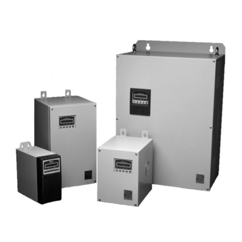
Zener SMARTSTART 6000 User manual

ZENER VARIDRIVE SOLUTIONS
ZENER SMARTSTART® 6000
Networking Guide
Modbus RS485
Ethernet

I0055 RevB Page 2 SS6000 Networking Guide
IMPORTANT – Read this first !
Each device on a Modbus RS485 serial bus must have a unique address; otherwise abnormal behaviour
of the whole bus can occur, potentially inhibiting communication with all devices.
Only one network client must control and/or configure a Smartstart® 6000 at any given time, otherwise
conflicts in register writes can arise which may result in unexpected behaviour or compromise
system/motor protection. Network security must be in place to prevent access by unauthorised
network clients.
On changeover between local and network control and vice versa, the motor may start or stop
depending on the state of the new command source (local or network). This may result in an
unintended operation on change of a configuration parameter or on change of state of the ‘Local’ input.
The local and network control system (e.g. PLC) must to be designed to satisfy the system’s safety and
operational requirements. Edge sense start logic (A53) and/or 3-wire control can be utilised to help
avoid unintended motor starts.
Essential Services Override (ESO) request via network should only be used as backup to the normal local
ESO request. Contact Zener for more information on ESO operation and associated risks.
Where Smartstart® 6000 configuration via network is utilised, network client (e.g. PLC) programming
must be suitably designed and validated. Incorrect changes to Smartstart® 6000 settings may cause
unexpected system behaviour and/or compromise motor/system protection.
This guide must be read in conjunction with the Smartstart® 6000 User Manual [1].
PLEASE NOTE:
This manual applies to Firmware Revision 1.30 and later. Earlier revisions will not support
some functions like changing of parameters via communications.
Data Logger and SD card slot:
The Modbus TCP/IP option board includes a Data Logger and SD card slot. The logged data is saved to
an SC card when fitted and cannot be accessed using communications.
For more information on the data logging function refer to the Data Logging Option manual document:
[IM]I0057.
This manual and other manuals for the Smartstart® 6000 can be found on the support page:
http://www.zener.com.au/support-6.php

I0055 RevB Page 3 SS6000 Networking Guide
Contents
1 Introduction ........................................................................................................................................5
1.1 References ..................................................................................................................................5
1.2 Definitions...................................................................................................................................6
2 Getting Started ...................................................................................................................................7
2.1 Prepare Check List.......................................................................................................................7
2.2 Configure Network Settings ........................................................................................................8
2.3 Connect to Network ....................................................................................................................8
2.4 Provision System for new Starter ................................................................................................8
3 Network Diagnostics ...........................................................................................................................9
3.1 Network Status Summary ...........................................................................................................9
3.2 Network Alarms ........................................................................................................................10
3.3 Network Diagnostic Menu ........................................................................................................10
4 Network Protocols ............................................................................................................................11
4.1 Modbus Protocol.......................................................................................................................11
4.1.1 Modbus Function Codes....................................................................................................11
4.1.2 Modbus Exception Codes ..................................................................................................11
4.1.3 Modbus Map.....................................................................................................................11
5 Starter Monitoring and Control ........................................................................................................12
5.1 Starter Status ............................................................................................................................12
5.2 Network Control Permission/Enable.........................................................................................12
5.3 Control Command Flags ............................................................................................................12
5.4 Network Control Status Flags ....................................................................................................13
5.5 Network Control Methods ........................................................................................................13
5.6 Network Control Timeout and Restoration...............................................................................13
5.7 Operating Motor when Network is down .................................................................................13
5.8 Local/Network Changeover.......................................................................................................13
6 Starter Configuration ........................................................................................................................14
6.1 Network Configuration Access ..................................................................................................14
6.2 Configuration Command Flags ..................................................................................................14
6.3 Network Configuration Status Flags..........................................................................................14
6.4 Configuration Errors..................................................................................................................14
6.5 Configuration Memory Model and Operations.........................................................................15
6.5.1 Local Configuration Edit ....................................................................................................15

I0055 RevB Page 4 SS6000 Networking Guide
6.5.2 Configuration Save ............................................................................................................15
6.5.3 Configuration Update........................................................................................................15
6.6 Configuration Application Examples .........................................................................................16
6.6.1 Auto Configure after Starter Replacement........................................................................16
6.6.2 Adjust Ramp Settings between Starts ...............................................................................16
7 Data Representation .........................................................................................................................17
7.1 Supported Data Types...............................................................................................................17
7.2 Data Encoding (Byte Order) ......................................................................................................17
7.3 Units of Measurement ..............................................................................................................17
7.4 Encoding of Status Objects (Read Only) ....................................................................................18
7.5 Encoding of Setting Objects (Read/Write) ................................................................................19
8 Network Protocol Specifications .......................................................................................................22
8.1 Modbus Application Layer ........................................................................................................22
8.2 Modbus over RS485 ..................................................................................................................22
8.3 Modbus over TCP ......................................................................................................................23
9 APPENDIX A: Modbus Map ...............................................................................................................24

I0055 RevB Page 5 SS6000 Networking Guide
1Introduction
The Smartstart® 6000 supports the following networking features:
•Modbus RTU over EIA/RS-485 via embedded interface (3 wire cabling – screw terminal)
•Modbus over TCP via Ethernet option board (CAT 5, RJ45 connector)
•Monitoring, control and configuration of the SmartStart® 6000 via network
•Motor stops on a network timeout error (soft-stop or trip options)
•Digital input supports an override switch (force ‘Local’ control and configuration)
•Configurable network access permissions
•Comprehensive network diagnostic alarms and screens
•Easily configured via the Network menu
1.1 References
This document uses ‘[n]’ shorthand to reference the following documents:
[1]
SS6000 Soft Starter User Manual, IMI0042, Zener Electric (www.zener.com.au)
[2]
APPENDIX A: Smartstart® 6000 Modbus Map
[3]
Modbus Application Protocol Specification V1.1b3 (www.modbus.org)
[4]
Modbus over Serial Line Specification and Implementation Guide V1.02 (www.modbus.org)
[5]
Modbus Messaging on TCP/IP Implementation Guide V1.0b (www.modbus.org)
[6]
Basics of the RS-485 Standard, Technical Article, B&B Electronics (www.bb-elec.com)
[7]
RS-422 and RS-485 Applications eBook v1.0, B&B Electronics (www.bb-elec.com)

I0055 RevB Page 6 SS6000 Networking Guide
1.2 Definitions
0x
Prefix for hexadecimal number (base 16)
AOK
All Okay
AR
Auto Reset/Restart. Automatically attempts to reset trip and restart motor.
CAT5
Category 5 (or 5e) cabling for Ethernet over twisted pair
CIDR
Classless Inter-Domain Routing (IP address format #.#.#.#/#)
Client
A device (e.g. PLC or SCADA) that initiates requests (also see master)
Coast
Free-wheel stop
Commit
A command issued by the network client to save configuration settings to NVM
Common
The signal common in the EIA/TIA standards
CRC
Cyclic Redundancy Check (detects communication errors)
Device
Electronic component connected to network (client or server)
DHCP
Dynamic Host Configuration Protocol (e.g. automatic IP address assignment)
EN
Local ‘Enable’ digital input. Must on to accelerate and run motor.
Enable
An input or flag that enables local/network control/configuration (check context).
ESO
Essential Services Override
FC
Function Code (Modbus definition)
FE
Framing Error (invalid stop bit)
HMI
Human-Machine Interface (e.g. console)
IP
Internet Protocol
LAN
Local Area Network (e.g. TCP/IP over Ethernet with CAT5 cabling)
LEN
Length (e.g. length error – packet too short or broken up)
Local
Local control and/or configuration (e.g. configurable input to ‘force local’)
LSB
Least Significant Bit (bit 0)
Master
Legacy term for client (e.g. RS485 terminology)
N/C
Normally Closed
Net
Network (or bus)
NG
Networking Guide (this document)
N/O
Normally Open
NVM
Non-Volatile Memory (e.g. EEPROM)
OR
Over Run (character overrun error)
Par2
A control input or flag used to select 2nd set of ramp control settings (when ON/TRUE)
PC
Personal Computer
PE
Parity Error
PLC
Programmable Logic Controller (network client/master)
RAM
Random Access Memory
Req
Request (from client to server)
Reset
Normally refers to trip reset. This can also trigger a motor restart.
Rollback
A command issued by the network client to retrieve last save configuration settings
ROM
Read Only Memory
Rsp
Response (from server back to client)
RTU
Remote Terminal Unit or a reference to the Modbus binary transmission mode
SCADA
Supervisory Control And Data Acquisition
Server
A device (e.g. Smartstart® 6000) that sends responses back to client (also see slave)
Slave
Legacy term for server (e.g. RS485 terminology)
TCP
Transmission Control Protocol
T/O
Timeout
Unit ID
Modbus TCP header field used to address serial line slave devices via gateway
XC
eXception Code (Modbus definition)

I0055 RevB Page 7 SS6000 Networking Guide
2Getting Started
2.1 Prepare Check List
Prepare for commissioning on network by filling in the following check list.
Item / Description
Parameter
Default
Setting
Configure
Network protocol:
Disabled; Modbus/RS485; or Modbus/TCP.
N01 Net Protocol Disabled
Control via network and timeout behaviour:
Disabled; Stop On T/O; or Trip On T/O. Note 1.
N02 Net Control Disabled
Set control data loss timeout:
0.1 to 60.0 seconds.
N03 Net Timeout 5.0s
Configure via network:
From ‘Disabled’ to ‘All Settings’. Note 2 & 3.
N04 Net Config Disabled
MB /
RS485
Address: 1 to 247
N10 RS485 Addr
0
Speed: 4800 to 38400 baud
N11 RS485 Speed
19k2
Format: 8e1, 8o1, 8n1 or 8n2
N12 RS485 Format
8e1
Modbus
/ TCP
Set static IP Address or 0.0.0.0 for
automatic assignment.
N20 IP Address
0.0.0.0
(DCHP)
Set number of 1’s in the subnet mask
(CIDR notation). N25 IP Mask Bits /24
Connect
Are site schematics or network cabling
guidelines available?
Phone number for SCADA control centre (if
applicable).
Modbus
/ RS485
Have suitable RS485 line terminators
been installed at each end of line?
Have suitable RS485 line polarisation
resistors been installed?
Provision
Who will program and configure the network
client (e.g. PLC) to work with the Smartstart®?
Notes:
1. Enabling Net Control (N02) restricts local control functionality. Consider configuring a digital
input as ‘Local’ to allow changeover to full local control.
2. Enabling Net Config (N04) disables setup by local user via console. Consider setting N04 last or
configuring a digital input as ‘Local’ to allow changeover to local setup.
3. Important settings can be protected by setting N04 to an appropriate network configuration
access level (see table in section 6.1).

I0055 RevB Page 8 SS6000 Networking Guide
2.2 Configure Network Settings
It is generally preferable to configure the network settings last, after all other
settings have been configured. Enabling N04 Net Config will disable local user
configuration access to other settings. Consider using the ‘Input’ menu to
configure a digital input as ‘Local’ to allow for local override.
Configure the Smartstart® 6000 network settings before connecting it to a live network as incorrect
settings could disrupt network communications. Use the console buttons to access the ‘Network’ menu.
Set and review parameters as per the check list. Press [ESC] to exit the menu system. Settings changes
take effect after menu exit and motor off.
2.3 Connect to Network
Before connecting the Smartstart® 6000 to a network, make sure the requirements for shielding,
twisted pairs, signal common, line termination and line polarisation are understood (see section 8
Network Protocol Specifications). The Smartstart® 6000 provides following network terminals.
Smartstart®
Terminal
Modbus
Name [4]
EIA-485
Name
Recommended
Wire Colour [4]
Description
17: SCREEN
-
-
Shield
Protective ground
22: RS485 DATA+
D1
B/B’
Yellow
High when bus idle (Note 2)
23: RS485 DATA-
D0
A/A’
Brown
Low when bus idle (Note 2)
24: RS485 COM
Common
C/C’
Green
Signal common (isolated)
ETHERNET PORT
-
-
CAT5 cable
RJ45 on RHS of Smartstart® 6000
Procedure:
1. Inform system control of task activity (e.g. possible alarms or disruptions)
2. Isolate Smartstart® 6000 (control and power circuits)
3. Wire network cabling to Smartstart® 6000 terminals per above table (Notes 2 and 3)
4. Turn Smartstart® 6000 on and check ‘Net’ status on the time/date screen (e.g. ‘Live’)
5. Inform system control of task completion (e.g. ready to provision for new Smartstart®)
Notes:
1. Incorrect configuration can disrupt the network (e.g. address must be unique).
2. Some vendors use A/B naming opposite to the EIA-485 standard.
3. Unplugging the Modbus RS485 connector also breaks the motor thermistor circuit.
2.4 Provision System for new Starter
The Smartstart® 6000 is provisioned into a system by programming and configuring the network client
(e.g. PLC). Information is this guide is provided to assist this process. Once provisioned, check the
time/date screen to confirm Smartstart® 6000 is communicating correctly (e.g. Net status shows
‘RxOk’).
After the starter is correctly provisioned on the network, it is possible for a
network client to automatically identify and configure the Smartstart® 6000 to
suit the site and application. See chapter 6 for more information.

I0055 RevB Page 9 SS6000 Networking Guide
3Network Diagnostics
3.1 Network Status Summary
The network status summary is shown on the RHS of the time & date dashboard screen:
17:25:45 Net*
14 Apr 2013 RxOk
The clockwise rotating ‘event wheel’ indicates the approximate rate of network transactions.
Status
Text
Status Description Possible causes / solutions
Off Networking is disabled
Networking has not been configured. Check setting
of ‘Net Protocol’ parameter.
Boot Network adapter is initialising
Network adapter option board (e.g. Ethernet) is
initialising.
Idle Network is idle (no activity)
Smartstart® 6000 is not connected; network client
is not connected or not running.
Live Network is active, but the
Smartstart® 6000 is NOT addressed
A network client is not programmed and/or not
provisioned to address the Smartstart® 6000. The
Smartstart® network address is not set correctly.
FLT! Network adapter fault
Network adapter (e.g. Ethernet option board) is not
detected or faulty (warning alarm is also raised).
BRK! Communication break condition
Network wire is broken, short-circuited or reverse
polarity. Check suitable line terminators and biasing
resistors are installed. Check network wiring.
ERR! Communication error occurred.
Message is corrupt (discarded)
Data link settings are incorrect (baud, parity, stop
bits, etc.), faulty cabling (wiring, termination,
screening) or significant signal interference. Note 1.
BAD! Processing exception occurred.
Request is invalid (discarded)
The Smartstart® 6000 is being addressed okay (no
data link errors), but request is invalid. Check
network client (e.g. PLC) programming. Note 1.
RxOk Request processed normally
Smartstart®6000 is receiving and processing
requests normally. Note 2.
Ctrl Control request accepted
Smartstart® 6000 recently received and accepted a
control command write request. Note 2.
Conf Configuration request accepted
Smartstart ® 6000 recently received and accepted a
configuration write request. Note 2.
Notes:
1. The Network Diagnostic menu can be used to further diagnose communications errors (ERR!)
and processing exceptions (BAD!).
2. The ‘Ctrl’ and ‘Conf’ messages take precedence over ‘RxOk’. They indicate that a control or
configuration request was accepted (within last 3s). Control and configuration requests can be
blocked by asserting the ‘Local’ input or changing the network settings (‘N02 Net Control’
and/or ‘N04 Net Config’).
Event wheel
Status text

I0055 RevB Page 10 SS6000 Networking Guide
3.2 Network Alarms
Network alarms indicate unusual network activity (e.g. incompatible client programming, rogue client,
etc.). Warnings W17 or W18 can occur while the ‘Local’ input is asserted (i.e. force local).
Network Alarm
Comments
W06 NET CTRL T/O
Warns of pending control data loss timeout (when ‘Net Control’ enabled).
T06 NET CTRL T/O
Network controlled motor tripped due to control data loss timeout.
W16 NET REQ BAD
Invalid request. See exception code (XC) on “C3:ReqsBad”diagnostic screen.
W17 NET CTRL BLK
Control request blocked (i.e. by ‘Net Control’ par or ‘Local’ input).
W18 NET CONF BLK
Configuration request blocked (i.e. by ‘Net Config’ par or ‘Local’ input).
W19 NET CONF ERR
Configuration data discarded as value was out of bounds (range error).
T19 NET CONF ERR
Motor start attempted after ‘NET CONF ERR’ warning. Check client program.
T39 NET TRIP SIG
Network client tripped operating motor via the ‘Trip’ control command flag.
3.3 Network Diagnostic Menu
The network diagnostic menu provides comprehensive network diagnostic information including the
diagnostic counters as defined in the Modbus specification [4]. Press the [RESET] key to clear the
counters. Use this menu to diagnose network communication and/or measure transaction rate.
Network Diagnostic
Screen
Description
Net Status Ctrl*
Diag Flags 003Ah
Network status text and event wheel as per “Network Status Summary”.
Network Diagnostic Flags (in hex) as per Smartstart® Modbus map [2].
C0:ReqsAok 12345
C1:BusMsgs 12345
Count of requests processed normally. Note 2.
Count of error-free bus messages. Note 4.
C2:BusErrs 12345
FE PE OR LEN CRC
Count of bus messages with a data link communication error. Note 4.
Shows “No comms errors” or lists the type of errors detected. Note 5.
C3:ReqsBad 12345
A001 FC016 XC002
Count of invalid (bad) requests received (processing exception occurred).
Shows “No exceptions” or the last exception (bad request). Note 6.
C4:ReqsRxd 12345
A001 FC023 okay
Count of requests received (with or without exceptions).
Shows “No requests” or the last function code. Note 6 and 7.
C5:ReqCast 12345
C6:RspNaks 12345
Count of broadcast requests received.
Count of exception responses sent.
C7:RspBusy 12345
C8:OvrRuns 12345
Count of busy responses sent (always zero for Smartstart® 6000).
Count of messages detected with a character overrun error.
Notes:
1. Press [RESET] to clear all diagnostic registers and counters (only when in this menu).
2. C0 is the event counter described in [3] for FC 11 “Get Comm Event Counter”.
3. C1 to C8 correspond to the serial line diagnostic counter numbering as defined in [4].
4. Regarding C1 & C2, the Smartstart® does not error check messages to/from other devices.
5. Errors shown: framing, parity, overrun, length and CRC (FE, PE, OR, LEN & CRC).
6. Shows device address (A) & function code (FC). If applicable exception code (XC) is shown. A000
indicates a broadcast request. Meanings of exception codes (XC) are listed in [3].
7. For Modbus/TCP, the address (A) is the “Unit Identifier” from the Modbus/TCP header.

I0055 RevB Page 11 SS6000 Networking Guide
4Network Protocols
4.1 Modbus Protocol
Modbus/RS485 and Modbus/TCP share the same application layer protocol (fully defined in [3]).
4.1.1 Modbus Function Codes
Supported Functionality
Supported Modbus Function Codes
Read 16-bit registers
FC 03, 04 & 23
Write 16-bit registers
FC 06, 16 & 23
Notes:
1. A full list of supported function codes is given in section 8.1.
2. Input registers overlap and holding registers (i.e. FC 03 and 04 are functionally equivalent).
3. FC 23 (read/write multiple registers) performs write operation before read.
4.1.2 Modbus Exception Codes
Code
Name
Meaning
XC 01
Illegal Function
Request contained an unsupported function code
XC 02
Illegal Data Address
Request referenced an undefined register address (i.e. not in [2])
XC 03
Illegal Data Value
Error in request format (e.g. implied length is incorrect). Note 1.
XC 11
Gateway target device
failed to respond
The Smartstart® 6000 did not respond to a Modbus/TCP request.
Check ‘Net Protocol’ is set to Modbus/TCP. Check gateway device.
Notes:
1. XC 03 does NOT cover range error in data written to registers. The application layer will discard
configuration data that fails range check (see alarm ‘W19 NET CONF ERR’). The client should
read back configuration data where validation is required.
4.1.3 Modbus Map
The Smartstart® 6000 Modbus Map is fully defined in [2] and consists of the following groups:
Group Name
Access
Comments
Product Identification
Read Only
Model, version, etc. (constant data)
Trip Log
Read Only
Log of last 10 trips (persistent data)
Operation History
Read Only
Meters and counters (persistent data)
Operation Status
Read Only
Live status of Smartstart® 6000 operation (dynamic data)
Network Diagnostics
Read Only
Network diagnostic flags and counters (dynamic data)
Commands
Read/Write
Control and configuration commands. Note 2.
Settings
Read/Write
Configuration settings (parameters). Notes 2 & 3.
Notes:
1. Any request to: access undefined registers; write to read-only registers; or partially access long
data objects (> 16 bit) will return an exception response (XC 02).
2. A normal response is returned even when control or configuration writes are blocked (see W17
& W18) or configuration data is out of bounds (see W19). Writes can be blocked by assertion of
the ‘Local’ input or by network settings (see ‘Net Control’ and ‘Net Config’). The client should
read back configuration data when validation is required (e.g. use FC 23).
3. Data written to settings area is not saved to NVM unless a commit command is issued.
4. To avoid unexpected behaviour, ensure only one Modbus client writes to registers.
5. Ensure network security is in place to prevent writes from unauthorised clients.

I0055 RevB Page 12 SS6000 Networking Guide
5Starter Monitoring and Control
5.1 Starter Status
Network clients can read any defined data object at any time to monitor Smartstart® 6000 status.
5.2 Network Control Permission/Enable
Starter control via network is only permitted when all of the following are satisfied:
•‘N02 Net Control’ parameter is set to enable control via network
•‘Local’ input (D1 or D2) is NOT asserted (or not configured)
•Enable (EN) digital input is asserted
•Network client (e.g. PLC) is regularly writing to the Control Command register
•Network client has set the Control Command Enable flag
Notes:
1. When control via network is not permitted (e.g. ‘Net Control’ disabled or ‘Local’ asserted),
attempts to control the stater via network will raise the ‘W17 NET CTRL BLK’ warning alarm.
2. Both the EN input and the control command Enable flag must be asserted to start and run the
motor via network. Loss of either of these conditions will initiate motor ramp down. However
the EN input is not required (ignored) during an ESO request.
5.3 Control Command Flags
A network client can control the Smartstart® 6000 by regularly writing to the Control Command Flags
register [2]. The following control flags are supported.
Flag
Description
Reset
0->1 = Attempts to reset trip alarm. Motor may start.
Enable
1 = enables start and run of motor; 1->0 = initiates motor stop
Start
1 = start motor (provided Enable on and other conditions permit start)
Coast
1 = force free-wheel stop
ESO
1 = Essential Services Override request (ignores starter and motor protection). Note 4.
Trip
0->1 = force trip of operating motor. Raises ‘T39 NET TRIP SIG’ alarm.
Par2
1 = use alternate ramp settings (2nd set). This flag is sampled at breakaway only.
Notes:
1. Acceptance of Start flag is per Start Logic (A53) setting (level or edge sense).
2. Enable and Start can be logically coupled for simple run/stop control. Keeping the Enable and
Start flags asserted makes system highly available (when set for level sense start logic) and
motor will auto start whenever conditions permit (e.g. network restoration, trip reset,
restoration of line supply, activation of local enable input, etc.).
3. Where unintentional start must be avoided, review PLC Start flag logic, Start Logic (A53) setting
and/or Net Control (N02) setting (e.g. trip on network timeout).
4. ESO is only available when a programmable input has been configured for ESO (Inputs menu).
Network ESO request requires: Enable=1, Start=1, Coast=0 and ESO=1. Network ESO request
should only be used as a backup of the local ESO request. See [1] for warnings regarding the use
of the ESO mode.

I0055 RevB Page 13 SS6000 Networking Guide
5.4 Network Control Status Flags
The following status flags are useful to confirm network control of the Smartstart® 6000.
Register
Status Flag
Usage
Auxiliary Status Flags
Net Control Only
Network allowed to control Smartstart® 6000
“
Net Control Online
Network is controlling the Smartstart® 6000
Network Diagnostic Flags
Control Write Accepted
Network is controlling the Smartstart® 6000
5.5 Network Control Methods
There are number of terminal wiring options to support network control with or without local
changeover support. The following is applicable when ‘N02 Net Control’ is enabled.
Control
Method
Inputs
Used
Description
Network
Only
Enable
(bridged)
Enable is bridged to +24VDC. Motor start and stop are only controlled
by the network client. Local control is not available. If necessary, cycle
control supply to accept configuration changes (i.e. force motor restart).
Network
with Local
Stop
Enable
(switched)
Enable is wired to an N/C switch to provide local stop control. There is
no provision to force local start. Closing switch may initiate a motor
start (where PLC logic asserts Enable and Start flags).
Network
with Simple
Local control
Enable &
Local
Enable and Local are wired to a three (3) position changeover switch
(e.g. RUN/STOP/AUTO).This is simplest way to force local control of
motor start and stop.
Network
with Classic
Local control
Enable,
Local &
Start
Enable and Local are wired to a three (3) position changeover switch
(e.g. LOCAL/OFF/REMOTE) and Start is wired to N/O [START] button.
Start input is only functional when the ‘Local’ input is asserted.
5.6 Network Control Timeout and Restoration
The motor stops when writes to the Control Command Flags register cease for ‘N03 Net Timeout’. The
stop behaviour (normal stop or trip) is defined by the ‘N02 Net Control’ parameter. On restoration of
network communications, the motor may automatically start (when network Enable and Start flags are
on). This can be avoided by having PLC logic use a pulse timer for motor start, setting ‘A53 Start Logic’ to
edge sense, and/or setting ‘N02 Net Control’ to ‘Trip on T/O’. After a ‘T06 NET CTRL T/O‘ trip and
network restoration, the PLC is able to reset the trip condition by toggling the ‘Reset’ control command
flag.
5.7 Operating Motor when Network is down
If it is necessary to run motor when the network (or network client) is down, the Smartstart® 6000 will
need to changeover to a ‘local only’ mode. Be aware that the motor may start on changeover. Options
to change over to a local control mode are:
•Operate a changeover switch to force local control (assert the ‘Local’ input); or
•Change the ‘N02 Net Control’ parameter to ‘Disabled’ to permit local control.
5.8 Local/Network Changeover
Changing the state of the ‘Local’ input (force local mode) or the ‘N02 Net Control’ setting can change
the control source. Bump-less transfer is supported when control signals are same as previous source.
Depending on the state of the new control signals (Enable, Start, Stop & Coast), the motor may start or
stop on changeover.

I0055 RevB Page 14 SS6000 Networking Guide
6Starter Configuration
6.1 Network Configuration Access
Starter configuration via network is only permitted when all of the following are satisfied:
•‘N04 Net Config’ parameter is set to enable configuration via network (see table)
•‘Local’ input (D1 or D2) is NOT asserted (or not configured)
•Network client has recently set the Enable flag of the Configuration Command register
When configuration via network is not permitted (e.g. ‘Net Config’ disabled, ‘Local’ asserted, etc.),
attempts to configure the starter via network will raise the ‘W18 NET CONF BLK’ warning alarm.
N04 Net Config
Writable Setting Groups
Comment
0: Disabled
None
All settings are protected (read only)
1: Display Only
Display settings only
Set date and time
2: Adjust Ramps
Display & Ramp settings
Adjust ramp control
3: Input/Output
Display, Ramp, Input & Output
Configure terminal I/O
4: Restart
Display, Ramp, I/O & Restart
Configure resets and auto restart (AR)
5: All settings
Includes Protection & Motor settings
Network can fully configure the starter
6.2 Configuration Command Flags
The Configuration Command register [2] supports the following command flags.
Flag
Description
Enable
1 = Enable configuration operations via network. Auto-clears after 60s. Note 1.
Commit
0->1 = Save configuration settings to NVM. Note 2.
Rollback
0->1 = Recall configuration settings from NVM.
Notes:
1. Enable must be asserted to permit other configuration commands and allow writes to the
settings objects. Enable auto-clears after 60s to reinstate configuration write protection.
2. Commit should not be used too frequently as the internal NVM has a limited write cycle life.
6.3 Network Configuration Status Flags
The following configuration status flags [2] are supported.
Register
Status Flag
Usage
Special Mode Flags
Network Config Only
Only a network client can configure unit
“
Network Config Enable
Net config Enable flag recently set (60s T/O)
“
Network Config Action
Net config cmd change or settings write (3s T/O)
“
Network Config Blocked
Net configuration operation blocked (3s T/O)
“
Network Config Error
Net config settings range error (3s T/O)
Network Diag Flags
Config Write Accepted
Recent configuration write request accepted
6.4 Configuration Errors
Should a network client attempt to write any setting outside the valid range (see [2]), the data is
discarded and a warning alarm is raised (the W19 NET CONF ERR). Attempting to start the motor will
raise a trip alarm (T19 NET CONF ERR). Other alarms can be raised should other configuration checks fail
(e.g. ‘T80 MTR AMPS CFG’ for invalid motor amps setting). A trip reset operation is required to clear
these alarms (e.g. to allow motor start). Check network client programming against the protocol map
[2].

I0055 RevB Page 15 SS6000 Networking Guide
6.5 Configuration Memory Model and Operations
The network client must assert the configuration command Enable flag to be able to write to setting
objects (in RAM) and issue special commands (commit = save and rollback = load). Alternatively a local
user may override network configuration access by asserting the ‘Local’ input. In this case, any unsaved
settings automatically rollback (load) and the local user is able to edit/write setting objects (RAM). Any
changed settings auto-save to NVM when the user exits the setup menu.
Operation
Network Client
Local User
Comment
Write
Set Enable flag &
write to setting
object(s)
‘Local’ input ON;
enter setup menu
& edit settings
Only one client has write access to
setting objects at any given time
Abort
Network client loses
config access (e.g.
‘Local’ activated)
Local user loses
config access (e.g.
‘Local’ deactivated)
Settings rollback to last saved values
(Load). Abort also forces ‘update’ if
motor is off.
Save
Commit command
Exit setup menu
Setting changes are saved to NVM
Update
Write complete and
motor off
Exit setup menu
and motor off
After write/edit completed, changes
take effect when/after motor is off.
Load
Rollback command
or abort
Control supply start
or abort
Load settings from NVM.
Defaults Not available
‘Restore Defaults’
command
Retrieve factory defaults from ROM (to
NVM & RAM).
6.5.1 Local Configuration Edit
While the network has configuration access, a local user can only edit the ‘Network’ settings. Other
settings return ‘NET CONF ONLY’. The easiest way to get full local configuration access is to force local
with the ‘Local’ input. Where this is not available, change ‘N04 Net Config’ to ‘Disabled’.
6.5.2 Configuration Save
Configuration changes made by a network client are not automatically saved. A network client can issue
the commit command to save changes. Configuration changes made by the local user are automatically
saved when the user exits the setup menu.
6.5.3 Configuration Update
While configuration changes can be made at any time, the changes will not take effect until the motor is
off (i.e. ramp down complete). A local user must also have exited the setup menu. If required, a local
user can force motor OFF by turning the EN input or the control supply OFF.
Saved Settings
(NVM)
Setting Objects
(RAM)
Default Settings
(ROM)
Save
SS6000
Logic
Update
Defaults
Network Client
Load
Console
Local
User
Network
Write
‘Local’ input
Config
Enable
flag
Smartstart® 6000

I0055 RevB Page 16 SS6000 Networking Guide
6.6 Configuration Application Examples
6.6.1 Auto Configure after Starter Replacement
For some applications it is desirable that the system automatically configure an exchanged Smartstart ®
6000. This requires installer and network client (e.g. PLC) to perform certain steps:
Who
Step
Description
Installer
Change out Smartstart® 6000
Replace Smartstart® 6000 and reconnect all wiring.
Configure network settings
Edit network settings as required so network client can
access the new Smartstart® 6000. This must include
setting ‘N04 Net Config’ to ‘All Settings’.
Network
Client
(e.g. PLC)
Detect need to reconfigure
Smartstart® 6000
When Smartstart® 6000 comes online, read all settings
and compare with expected values. Mismatch
indicates Smartstart® 6000 needs to be reconfigured.
Write required settings
Write required settings to Smartstart® 6000. Read back
settings to validate configuration (recommended).
Commit setting changes
Issue commit command to save settings to NVM.
Installer
Check settings
Use menu system to check the Smartstart® is
configured as expected to suit installation.
Protect settings (optional)
Option to protect configuration settings by setting
‘N04 Net Config’ to ‘Disabled’; ‘Display Only’; etc.
Test new Smartstart® 6000
Test motor ramp up and ramp down to confirm
operation is correct for installation.
6.6.2 Adjust Ramp Settings between Starts
For some applications it is desirable to adjust the ramp control settings regularly (e.g. between motor
starts). During commissioning, the Smartstart® 6000 is configured to suit the primary application (either
by a local user or by the network client). If desired, ‘N04 Net Config’ can then be set to ‘Adjust Ramps’
and thereby protect critical Smartstart® 6000 settings (e.g. so protection settings cannot be changed).
Between motor starts, the network client can write new ramp control settings ready for the next start
(stored in shadow RAM). The commit command should not be used for this type of application (i.e.
maximise the life of Smartstart® 6000 NVM).

I0055 RevB Page 17 SS6000 Networking Guide
7Data Representation
This section defines how different Smartstart® 6000 data objects are represented over a network.
7.1 Supported Data Types
Data Type
Length
(bits)
Minimum
Value
Maximum
Value
Description
BOOLEAN
1
0 = False (off)
1=True (on)
Logical flag (typically packed in UINT16)
UINT8
8
0
255
8-bit unsigned integer
INT8
8
-128
+127
8-bit signed integer
UINT16
16
0
65,535
16-bit unsigned integer
INT16
16
-32,768
+32,767
16-bit signed integer
UINT32
32
0
4,294,967,295
32-bit unsigned integer
INIT32
32
-2,147,483,648
+2,147,483,647
32-bit signed integer
BCD16
16
0x0000
0x9999
16-bit binary coded decimal (4 digits)
BCD32
32
0x00000000
0x99999999
32-bit binary coded decimal (8 digits)
ASCII[n]
8*n
32 = ‘ ‘ (Space)
126 = ‘~’ (Tilde)
Array of printable ASCII characters
7.2 Data Encoding (Byte Order)
Protocol
Byte order
Comments
Modbus
Most significant byte sent first
Also known as big-endian or network order
Notes:
1. Modbus only defines how to encode 16-bit registers. The Smartstart® also uses the big-endian
convention for larger data objects so the first register contains the most significant 16-bits. For
example a UINT32 of value 200,000 is encoded as reg[N] = 3 & reg[N+1] = 3392.
7.3 Units of Measurement
Following are examples of units used by Smartstart® 6000 to represent quantities over a network.
Units
Descriptions
Data Object Example
0.1 %
Permille (parts per thousand)
Ramp Progress
%
Percentage (parts per hundred)
C12 Start Torque
0.1 s
Time in tenths of a second
A11 Kick Time
s
Time in seconds
C11 Accel Time
0.1 min
Time in tenths of a minute (6 s)
A52 Minimum Off Time
0.1 hr
Time in tenths of an hour (360 s)
Operating Meter
0.1 Hz
Frequency in tenths of a Hertz
Line Frequency
C
Temperature in degrees Celsius
A42 Starter Over-temperature Reset Level
0.1 A
Current in tenths of an ampere
M01 Motor Amps
0.1 V
Voltage in tenths of a volt
Line Voltage
V
Voltage in volts
M02 Motor Volts
W
Power in Watts
Input Power
0.1 kWh
Energy in tenths of a kWh
Energy Meter
count
Number of items, events, etc.
Trip Counter
code
Numeric code (see encoding below)
Last Trip Code
ENUM
Enumeration (see encoding below)
Operating State

I0055 RevB Page 18 SS6000 Networking Guide
7.4 Encoding of Status Objects (Read Only)
The units for most status objects are defined in the protocol map [2]. The following table lists special
encoding of status objects (i.e. where units specified as ‘code’ or ‘ENUM’).
Status Object
Encoding
Description
Product Identifier
0x5560
Read this to check the device is actually a
Smartstart® 6000. Also consider checking
other ‘Product Identification’ objects.
Trip Log # / Trip Code
Active Alarm / Alarm Code
Last Warning Code
Last Trip Code
0: No alarm
1…99: see [1]
Alarm code/number. See list in user manual
[1]. Used for logged trip alarm, current active
alarm, last warning alarm, and last trip alarm.
Active Alarm / Alarm Type
0: ‘I’: Interlock
1: ‘W’: Warning
2: ‘T’: Trip
Indicates type of alarm.
Trip Log # / Operating State
Operating State (Note 1)
0: ‘O’ Off
1: ‘S’ Standby
2: ‘R’ Ready
3: ‘Y’ Start Delayed
4: Reserved
5: ‘K’ Kick Start
6: ‘A’ Accelerating
7: ‘U’ Up To Speed
8: ‘V’ Overtime
9: ‘C’ Continuous
10: Reserved
11: ‘B’: Bypass
12: ‘D’ Decelerating
13: ‘w’ Deflux wait
14: ‘W’ Cooling wait
15: ‘T’ Tripped
16: ‘P’ AR Pending
17: ‘L’ AR Lockout
18: ‘Z’ Shutdown
19: ‘z’ Brownout
Line supply off and enable off
Line supply off and enable on
Line supply on and enable off
Start delay due to cooling or min off delay
Future use
Kick start active
Accel timer active but not up to speed
Accel timer active and up to speed
Accel timer expired and not up to speed
Continuous conduction (full volts on motor)
Future use
Bypass contactor closed (full volts on motor)
Deceleration ramp down active
Short wait to deflux after motor turns off
Waiting for starter and/or motor to cool
Starter has tripped. See Trip Code for cause.
Tripped, but auto reset/restart is pending
Final trip after all AR attempts exhausted
Control supply shutdown detected (normal)
Persistent control supply under-voltage(fault)
Notes:
1. The op code shown (e.g. ‘B’ for Bypass), is the format displayed in trip log and data logger.

I0055 RevB Page 19 SS6000 Networking Guide
7.5 Encoding of Setting Objects (Read/Write)
The units and range of most setting objects are defined in the protocol map [2]. The following tables list
special encoding used for setting objects (i.e. where units specified as ‘code’ or ‘ENUM’)
Advanced Setting
Encoding
Description
A21 Acceleration Profile
A31 Deceleration Profile
0: Linear
1: Squared
Ramp shape can be configured to be a straight
line or a quadratic (parabola).
A22 Acceleration Control
A32 Deceleration Control
0: Voltage
1: Torque
Ramp can be configured for open-loop voltage
control or closed-loop torque control
A53 Start Logic
0: Level Sense
1: Edge Sense
Select logic to use with start signal. Start signal is
via network request or local input (EN or Start).
Control Setting
Encoding
Description
C01 Run Mode
0: Bypass (default)
1: Continuous
Set operating mode for when motor up to
speed and acceleration time has expired
Display Setting
Encoding
Description
D01 Menu Access
1: Disabled
2: Read Only
3: Setup (default)
Set level of access a local user has to view
and/or change settings. For high security
the menu can be hidden or read-only.
D02 Default Screen
1: Clock & Net
2: Overview (default)
3: Thermal Cap.
4: Electrical
5: Power/Torque
6: Voltage Imbalance
7: Current Imbalance
8: Counters
9: Meters
Set the default screen for display on
console. The other dashboard screens can
be viewed at any time by scrolling with
the [Up] and [Down] keys. The overview
screen (default) includes a configurable
bargraph.
D03 Bargraph Variable
1: Motor Current (def)
2: Motor Torque
3: Motor Thermal
4: Stater Thermal
5: Active Power
6: Power Factor
Select variable to display on bargraph.
D04 Bargraph Full Scale
0: 100%
1: 120%
2: 150%
3: 200%
4: 300% (default)
5: 400%
6: 600%
Set the full scale of bargraph display.
Select value to best suit the expected
range of the selected bargraph variable
(D03).
D05 Flash Alarms
D06 Alarm Over Bargraph
0: Disabled
1: Trips Only
2: Fault Warnings
3: Major Warnings
4: All Warnings
5: All Alarms (default)
Set filter level for display of alarms. Can
filter alarms that are flashed over
dashboard screen. Can filter alarms that
override bargraph when motor is off (e.g.
stop interlocks).

I0055 RevB Page 20 SS6000 Networking Guide
Motor Setting
Encoding
Description
M03 Motor Wiring
1: Standard 6 wire
2: Alternate 6 wire
3: Three wire (default)
Set how motor is wired to starter. Only
applicable for starter models that support
6-wire motors.
Protection Setting
Encoding
Description
P01 Motor Over Load Class
0: Disabled
1: Class 2
2: Class 10a
3: Class 10 (default)
4: Class 15
5: Class 20
6: Class 25
7: Class 30
Set the thermal overload class of the
connected motor where i2t thermal
overload protection is required.
P02 Motor Over Temperature
0: Disabled (default)
1: N/C Switch
2: PTC Thermistor
Set type of motor temperature probe
used for motor over temperature
protection.
P03 Phase Rotation
0: Ignore (default)
1: 1-2-3 (normal)
2: 3-2-1 (reverse)
Set required phase sequence of line
supply. Can be used to prevent pumps
running in wrong direction.
P11 Overtime Alarm
P21 Voltage Imbalance Alarm
P31 Current Imbalance Alarm
P41 Under Current Alarm
P51 Over Current Alarm
P61 Under Torque Alarm
P71 Over Torque Alarm
0: Off
1: Warn
2: Trip
Set alarm level of different protection
features. Protection alarm can be disabled
(0), warn only (1) or warn and trip (2).
Note that warning thresholds are defined
either by A43 Warning Level or A44
Warning Delay.
Input Setting
Encoding
Description
X10 Digital Input 1 Mode
X20 Digital Input 2 Mode
0: Disabled
1: Enabled
2: Inverted
Set to enable digital inputs (D1 & D2). The
polarity can be set to suit application.
X11 Digital Input 1 Variable
X21 Digital Input 2 Variable
0: Trip
1: Reset
2: Start
3: Stop
4: Coast
5: Local
6: ESO
7: Par2
8: Brake On
Select required function for digital inputs
(D1 & D2).
Other manuals for SMARTSTART 6000
1
Table of contents
Other Zener Controllers manuals