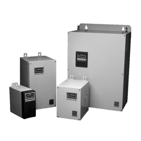
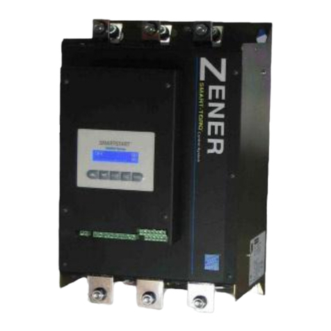
Zener 8000-V User manual

ZENER VARIDRIVE SOLUTIONS
ZENER 8000-V
Installation Manual
Document: IM00165
Printed: 27 February 2019

IM00165
PRODUCT
This manual provides installation information for the following ZENER 8000 models;
8V : 950 to 1100VAC
This manual provides basic control configuration information to suit more
common applications. Please refer to the ZENER 8000 Reference Manual
IM00140 http://www.zener.com.au/images/im00140.pdf for a detailed
explanation of each control feature, including communications protocols.
All documentation for this product can be found on our product support link:
http://www.zener.com.au/support-zener.php
ZENER TECHNOLOGY AND QUALITY ASSURANCE
Since 1976 Zener Electric has supplied many thousands of drives to industry. These drives have been installed
into numerous applications resulting in a wealth of in house experience. The ZENER 8000-V AC variable speed
controller is the culmination of this experience, modern technology and industrial application requirements.
The Zener Quality Assurance program ensures that every ZENER 8000-V manufactured has proven to operate
correctly in the production test bay before dispatch.
SAFETY
Your ZENER 8000-V must be applied, installed and operated in a safe manner. It is the responsibility of the user
to ensure compliance with all regulations and practices covering the installation and wiring of your ZENER 8000-
V. The instruction manual should be completely read and understood before attempting to connect or operate
the ZENER 8000-V. Only skilled personnel should install this equipment. This equipment contains a number of
components that are designated by their various manufacturers as “not for use in life support appliances,
devices or systems where malfunction of the components can reasonably be expected to result in personal
injury or death”. Customers using or selling Zener products for use in such applications do so at their own risk
and agree to indemnify Zener for any damage resulting from improper use or sale.
THE CONTENTS OF THIS MANUAL ARE SUBJECT TO CHANGE WITHOUT NOTICE
ZENER is a registered trademark of Zener Electric Pty Limited

ZENER 8000-V Installation Manual
IM00165 i
Contents
Explanation of symbols..............................................................................................................................................1
Warnings....................................................................................................................................................................1
Receiving....................................................................................................................................................................2
Software ....................................................................................................................................................................2
Installation.................................................................................................................................................................3
ZENER 8000-V mounting location .........................................................................................................................3
Installation Information.........................................................................................................................................3
ZENER 8000-V Mechanical Installation Information .................................................................................................4
V1 Module .............................................................................................................................................................4
V1 Module dimensions......................................................................................................................................4
V1 Module mounting cut-out detail..................................................................................................................5
V1 Module mounting clearance requirements .................................................................................................6
V2 Module .............................................................................................................................................................7
V2 Module dimensions......................................................................................................................................7
V2 Module mounting cut-out detail..................................................................................................................8
V2 Module mounting clearance requirements .................................................................................................9
Remote console mounting ..................................................................................................................................10
Panel Cut-out...................................................................................................................................................10
Installation of Remote Console .......................................................................................................................10
ZENER 8000-V Power wiring....................................................................................................................................11
AC line overcurrent protection device ................................................................................................................11
Coordination of supply circuit protection and switchgear..................................................................................11
Cable sizes ...........................................................................................................................................................11
Electrical Isolation ...............................................................................................................................................12
Motor thermal protection...................................................................................................................................12
Power Wiring for Single Units .............................................................................................................................13
Power Wiring for Parallel Units...........................................................................................................................14
Control Interconnection for Parallel Units ..............................................................................................................15
Control Cable Diagram ........................................................................................................................................15
Control Connector Identification.........................................................................................................................15
Earth leakage currents in IT supply system environments......................................................................................16
Basic VSD power circuit.......................................................................................................................................16
Common mode voltage and capacitive currents.................................................................................................17
Nature of the capacitive leakage current........................................................................................................17
Capacitive leakage current path......................................................................................................................17
Magnitude of capacitive leakage currents ......................................................................................................18

Contents
ii IM00165
Earth leakage monitoring instruments / devices............................................................................................ 19
Q&A..................................................................................................................................................................... 20
This seems very different to 415V VFDs installations. Why? ......................................................................... 20
Will using a screened motor cable reduce the capacitive earth leakage currents?....................................... 20
How can I minimise the capacitive earth leakage current and its impact on the installation?...................... 20
Can I add an EMC filter on the AC line to the drive? ...................................................................................... 21
What are the implications for touch potential around the installation? ....................................................... 21
Can pilot earth circuits be used in cables associated with 1000V VFDs?....................................................... 21
What happens if the earth connection to the motor is disconnected? ......................................................... 21
Electromagnetic Compatibility (EMC)..................................................................................................................... 22
Installation practices and EMC ........................................................................................................................... 22
Screened power cables and alternative materials ......................................................................................... 23
EIA/RS-485 Communications Wiring ...................................................................................................................... 24
Best practice ....................................................................................................................................................... 24
Terminating resistors...................................................................................................................................... 25
General ........................................................................................................................................................... 25
Shortcuts......................................................................................................................................................... 25
Extended Features Option Wiring .......................................................................................................................... 26
ZENER 8000-V Start Up........................................................................................................................................... 27
Operation Displays & Pushbuttons..................................................................................................................... 28
Local Mode Operation Example ..................................................................................................................... 29
Complete Menu.................................................................................................................................................. 30
Application Menu ............................................................................................................................................... 31
Loading an Application ................................................................................................................................... 32
Application user menu.................................................................................................................................... 33
Changing an Application ................................................................................................................................. 33
Control connections and configuration.............................................................................................................. 34
General ........................................................................................................................................................... 34
Factory default settings .................................................................................................................................. 34
Settings for your application........................................................................................................................... 34
Quick Setup..................................................................................................................................................... 34
Control Inputs ..................................................................................................................................................... 35
Selecting Standard Input Configuration ............................................................................................................. 35
Standard Industrial Terminals............................................................................................................................. 37
Typical Connections........................................................................................................................................ 37
Setup Guide .................................................................................................................................................... 38
APPLICATION: Machine Drive, Start/Stop, Jog Forward & Reverse ................................................................... 41

ZENER 8000-V Installation Manual
IM00165 iii
Expected Wiring...............................................................................................................................................41
One Time Installation/Application choice .......................................................................................................41
Application Parameters...................................................................................................................................41
APPLICATION: Water Pumping With Automatic Pressure Control .....................................................................42
Expected Wiring...............................................................................................................................................42
One Time Installation/Application choice .......................................................................................................42
Operation.........................................................................................................................................................42
Application Parameters...................................................................................................................................43
Pressure Control Performance ........................................................................................................................44
Additional detailed information..............................................................................................................................45
Communications Protocols......................................................................................................................................45
Transport considerations.........................................................................................................................................45
Maintenance considerations...................................................................................................................................45
Spare parts...............................................................................................................................................................45
Packing for transport...............................................................................................................................................45
Display Messages.....................................................................................................................................................46
Fault Messages ....................................................................................................................................................46
Status Messages ..................................................................................................................................................47
Specifications...........................................................................................................................................................49
Output Current Specifications.............................................................................................................................51
Troubleshooting guide ........................................................................................................................................51
Your ZENER 8000-V Setup Notes.............................................................................................................................54
Appendix A - Electrical distribution earthing systems.............................................................................................58
Electrical earthing................................................................................................................................................58
Protective earthing..........................................................................................................................................58
Functional earthing..........................................................................................................................................58
Electrical supply earthing arrangements.............................................................................................................58
TN system ........................................................................................................................................................58
IT system..........................................................................................................................................................58
Glossary ...................................................................................................................................................................60

Contents
iv IM00165

ZENER 8000-V Installation Manual
IM00165 1
Explanation of symbols
WARNING
Indicates a condition or practice that, if the warning is not strictly observed,
could result in personal injury or death.
CAUTION
Indicates a condition or practice, if the caution is not strictly observed, could
lead to damage or destruction of equipment or a significant impairment of
proper operation.
WARNING
This symbol is used to highlight an electrical hazard. Failure to strictly observe
the warning could result in electrocution.
i
This symbol is used to highlight additional information on the product’s
capabilities or a common error in installation, commissioning or operation.
Warnings
Read all operating instructions before installing, wiring, operating, servicing or inspecting the
ZENER 8000-V.
Ensure that the instruction manual is made available to the final user of the product as well as
all personnel involved in any aspect of installation, adjustment or maintenance. Your ZENER
8000-V must be applied and installed by suitably qualified and experienced personnel in
accordance with this manual, good engineering practice and all local rules and regulations to
the end use environment.
There are hazardous voltages inside the ZENER 8000-V whenever it is connected to an electrical
supply and for some time afterwards.
Before touching anything inside the ZENER 8000-V enclosure or other equipment connected to
the ZENER 8000-V terminals, disconnect all sources of electrical power, wait at least 11 minutes
for capacitors within the ZENER 8000-V to discharge to less than 50VDC and then ensure, by
measurement, that there is no hazardous AC or DC voltage present at any terminal.
The ZENER 8000-V contains high energy circuits that may be hazardous. Do not operate ZENER
8000-V with the door open or any part of the enclosure removed.
Do not touch the terminals of the ZENER 8000-V or any associated motor and wiring when it is
energised, even if the ZENER 8000-V and motor are stopped. Electric shock may result.

ZENER 8000-V Installation Manual _
2 IM00165
Do not modify this equipment electrically, mechanically or otherwise. Modification may create
safety hazards.
The ZENER 8000-V is designed to drive an appropriately rated and otherwise suitable 3 phase
induction motor. It is not suitable for single phase motors or other types of motor or non-motor
load. Use with inappropriate load types may create a safety hazard.
Where the ZENER 8000-V is used as a component part of another product, it is the purchaser’s
responsibility to ensure that the final product meets all of the necessary safety, EMC,
regulatory, operational and other requirements for that product. Requirements for the
purchaser’s final product may be substantially different to the requirements for stand-alone
inverters.
The ZENER 8000-V is manufactured under strict quality control arrangements, however
additional and independent safety equipment must be installed if the application is such that
failure of the product may result in personal injury or property damage.
Ensure that electrical noise generated by the product and any associated equipment does not
adversely affect the proper operation of other equipment or systems, particularly those that
have a safety function.
Install emergency stop circuitry that removes power from the ZENER 8000-V and does not
depend on any feature of the product for proper and safe operation. Do not use the braking
functions of the product for safety purposes.
The ZENER 8000-V has features that may be used to cause an automatic restart in certain
circumstances. The overall application (machine etc) must be designed such that automatic
restart is not hazardous.
Do not install this equipment in locations where mechanical damage to the enclosure is
possible. In particular, consider vehicles, vandalism and attack by insects or animals. Severe
equipment damage and safety hazards may result.
Receiving
Inspect the ZENER 8000-V for any shipping damage. If any damage is found, report it to the carrier immediately.
Do not attempt to operate the ZENER 8000-V if any obvious damage exists.
After the initial inspection, the ZENER 8000-V can be repacked and stored in a clean, dry location until it is
required for use.
DO NOT store this equipment in an area where the ambient temperature will fall below -20°C or rise above
70°C. DO NOT store this equipment in areas that are subject to condensation or corrosive atmosphere. Proper
storage is necessary to ensure satisfactory controller start up and performance.
Software
This manual applies to ZENER 8000-V software revision 5.2.x. The software revision is displayed briefly at power
up and may also be viewed in the service menu.
i
This manual provides basic control configuration information for the ZENER 8000-V to suit
more common applications. Please refer to the ZENER 8000-V Reference Manual IM00140 for
a detailed explanation of each control feature, including communications protocols.

ZENER 8000-V Installation Manual
IM00165 3
Installation
ZENER 8000-V mounting location
The ZENER 8000-V chassis is intended to be mounted in a switchboard style enclosure with the heatsink section
protruding through the rear wall of the enclosure. The input and output line reactors provided as part of the
ZENER 8000-V should be mounted within the switchboard, adjacent to, or on the enclosure floor, below the
ZENER 8000-V module chassis. The control console is separate to the ZENER 8000-V chassis and intended to be
mounted on the front of the switchboard enclosure for convenient operation. Mechanical protection may be
required to prevent damage to the heatsink section in some environments. The ZENER 8000-V portion within
the user’s switchboard enclosure is designed for use in a pollution degree 2
1
environment. The system
integrator and user are responsible for providing and maintaining this environment inside the switchboard
enclosure under all circumstances for the lifetime of the equipment.
Installation Information
CAUTION
The ZENER 8000-V must be mounted in a vibration free situation with heatsink fins
protruding through the wall of a switchboard type enclosure.
Do not mount the ZENER 8000-V where it is subject to heating by direct sunlight or
other heat radiating sources.
ZENER 8000-V must be mounted vertically. No other mounting orientation is
acceptable.
The thermal design of the user’s switchboard enclosure must be accommodate the
total heat dissipation of the ZENER 8000-V components together with the heat
dissipation any other equipment in the same enclosure and maintain the internal
ambient temperature within the range of 0 - 50°C without condensation.
Attention is drawn to the potential for condensation in vulnerable environments.
Additional precautions may be required for all enclosure types.
All of the parts associated with a drive system using parallel modules must be
installed in the same enclosure.
The installation location and environment should provide for safe access and
working conditions for maintenance personnel.
The mechanical design of the enclosure should provide for the safe removal and
replacement of drive modules and line reactors for maintenance purposes in a way
that suits the circumstances of the final installation site.
Do not drill holes in the ZENER 8000-V module enclosure except in the gland
plates.
Remove the module gland plate before drilling cable holes.
Do not allow metal shavings or any other conductive material to enter the
ZENER 8000-V module enclosure or line reactors. Serious damage may result.
1
Any pollution present is non-conductive

ZENER 8000-V Installation Manual _
4 IM00165
758
420
403
69
660
127 40 40
663
225
225
269
64
316.5
104 33
30
30
103.5
19
102.5
TOP GLAND PLATE
Opening 94mm x 54mm
COOLING FAN
Allow access for removal EARTH STUD (M8)
620
125
TOP GLAND PLATE
Opening 94mm x 54mm
BOTTOM GLAND PLATE
Opening 94mm x 54mm
M1 TERMINAL
M2 TERMINAL
M3 TERMINAL
L1 TERMINAL
L2 TERMINAL
L3 TERMINAL
V1 Module dimensions
ZENER 8000-V Mechanical Installation Information
Each ZENER 8000-V system consists of one module or a number of modules for connection in parallel. There
are two physical sizes of module, V1 and V2, with a number of different electrical ratings available in each
physical module size.
V1 Module
The inverter modules for ratings up to 66A are of V1 dimensions.

ZENER 8000-V Installation Manual
IM00165 5
50
329
329
50
10 105 105 105 105 10
758718
380
420
25mm x 25mm x 3mm ANGLE
M6 TAPPED HOLE
for mounting clamp
M8 TAPPED HOLES
M6 TAPPED HOLE
for mounting clamp
M6 TAPPED HOLE
for mounting clamp
M6 TAPPED HOLE
for mounting clamp
M6 TAPPED HOLE
for mounting clamp
M6 TAPPED HOLE
for mounting clamp
CUTOUT
V1 Module mounting cut-out detail

ZENER 8000-V Installation Manual _
6 IM00165
MOUNTING CUTOUT
As shown on Sheet 2
150
150
150
1018
380
380
150
AIR EXHAUST
This area must be kept clear
AIR INTAKE
This area must be kept clear
150
150
1018
INVERTER HEATSINK
This area must be kept clear
CUSTOMER'S PANEL
CUSTOMER'S PANEL
100 100
403
760
V1 Module mounting clearance requirements

ZENER 8000-V Installation Manual
IM00165 7
758 mm
30 mm
19 mm
651 mm
663 mm
103.5 mm
40 mm 40 mm
30 mm
224.8 mm
224.8 mm
403 mm
620 mm
125 mm
127 mm
493.5 mm
64 mm
582.5 mm 43 mm
316.5 mm
64 mm
28 mm
104 mm
BOTTOM GLAND PLATE
Opening 94mm x 54mm
BOTTOM GLAND PLATE
Opening 94mm x 54mm
TOP GLAND PLATE
Opening 94mm x 54mm
COOLING FAN ASSEMBLY
Allow access for removal
L1 TERMINAL
L2 TERMINAL
L3 TERMINAL
M1 TERMINAL
M2 TERMINAL
M3 TERMINAL
EARTH STUD (M8)
25.5 mm
36.5 mm
200.5 mm
V2 Module
The inverter modules for ratings of 84A and above are of V2 dimensions.
V2 Module dimensions

ZENER 8000-V Installation Manual _
8 IM00165
V2 Module mounting cut-out detail
50.5 mm
328.5 mm
328.5 mm
50.5 mm
10 mm 130 mm 130 mm 130 mm 130 mm 10 mm
758 mm
718 mm
611 mm
651 mm
25mm x 25mm x 3mm ANGLE
CUTOUT
131 mm
20 mm
14 mm 20 mm
M6 TAPPED HOLE
for mounting clamp M6 TAPPED HOLE
for mounting clamp
M6 TAPPED HOLE
for mounting clamp
M6 TAPPED HOLE
for mounting clamp M6 TAPPED HOLE
for mounting clamp
M6 TAPPED HOLE
for mounting clamp
M8 TAPPED HOLES

ZENER 8000-V Installation Manual
IM00165 9
125 mm 150 mm
50 mm50 mm
150 mm
50 mm50 mm
758 mm
277 mm
494 mm
751 mm
CUSTOMER'S PANEL
CUSTOMER'S PANEL
277 mm
AIRFLOW
i
For installations with inverter modules mounted side by side, the minimum mounting
pitch horizontally is 751mm.
Systems that use parallel connected modules (ratings 200A and above) have the
additional requirements that the modules be mounted in a horizontal row with a
mounting pitch not exceeding 1100 mm.

ZENER 8000-V Installation Manual _
10 IM00165
Outline of console
Panel Cut-out (92mm x 66mm)
92mm
66mm
110mm
88mm
Clearance for CAT-5 connector
Remote console mounting
Panel Cut-out
Ensure space is allowed for the console and the CAT-5
connection as shown. Allow 70mm behind the panel to
accommodate the depth of the remote console.
Cut out the panel as shown in the drawing below.
Installation of Remote Console
The console is secured in position by the rear clamps. Do not over
tighten.
An Earth termination is available if the user would like to earth all
exposed metal components including the front panel. The console
only uses extra low voltage so earthing is not required.
With power removed from the ZENER 8000, connect the CAT-5 cable
supplied to the console & the ZENER Drive.

ZENER 8000-V Installation Manual
IM00165 11
ZENER 8000-V Power wiring
AC line overcurrent protection device
An overcurrent protection device is required in the AC supply to the ZENER 8000-V. The purpose of this device
is twofold:
To provide thermal protection for the cables etc between the location of the overcurrent
protective device (usually at the origin of the relevant supply sub‑circuit) and the ZENER 8000-V. This is
predominantly a measure to prevent injury and property damage from melting and fire.
To limit the energy available at the location of a short circuit or near short circuit in the
unlikely, but possible, event of a major arcing fault in wiring or within the ZENER 8000-V enclosure. This
measure is to control the risk of personal injury and property damage due to arc flash,
conductor erosion, explosion and the like.
The first requirement is relatively slow and normally provided by fuses or the timed (traditionally
referred to as thermal) characteristic of a circuit breaker. Note that the protection offered by this device on the
AC line side of the ZENER 8000-V does not extend to the output (motor) side because the AC line side current
may be considerably less than the ZENER 8000-V output current when operating at less than full speed. This is a
consequence of the high efficiency of the ZENER 8000-V and the power required by the load being a
product of torque and speed, the AC input power (and current) reduce with speed, even if the load torque
remains high. The ZENER 8000-V itself provides both timed overcurrent (I2t) and instantaneous overcurrent
protection for the output wiring and motor.
The second requirement may be met with either the instantaneous trip function of a circuit breaker or a fuse.
The total amount of energy let through in the event of a short circuit or near short circuit event is usually the
critical factor in determining the injury risk, extent of physical damage and consequently the time and expense
involved in repair. The let through energy may be accessed in terms of the I2t (time integral of current squared)
let through the protective device in the process of interrupting the fault current. In order to minimise the I2t let
through and the associated risks of injury, property damage and downtime, we recommend the use of
appropriately rated current limiting
2
type fuses. In some circumstances, the user’s protection needs may be
met by a suitably selected circuit breaker however, we strongly recommend that any such selection be based on
detailed engineering evaluation and not simply a catalogue selection.
Coordination of supply circuit protection and switchgear
Either fuses or a circuit breaker must be connected as shown. The protective elements used and any upstream
switchgear (contactors, isolation switches etc) must be selected with due regard for the prospective short
circuit currents of the electrical supply and the requirements of your local electrical code. The selection should
provide for “type II” (no damage) coordination as per IEC 60947 or Australian Standard AS 3947.
Cable sizes
Power cables between the various system components are the responsibility of the installer and the
size and type to be used should be selected to suit the application and on the basis of the continuous current
rating of the ZENER 8000-V and a minimum temperature rating of 70C. Cables sizes should be selected
according to local wiring rules using the currents given in the table on page 51. Note that the power
terminals of the ZENER 8000-V enclosure and the input/output line reactors are intended for use with
cables terminated in crimp lugs with a single hole to match the diameter of the hole or bolt provided.
2
“Current limiting” describes the ability of an overcurrent protective device (fuse or circuit breaker) to reduce the peak
current that flows in a circuit, by opening and clearing the fault in a sub half-cycle time frame.

ZENER 8000-V Installation Manual _
12 IM00165
Electrical Isolation
A suitable means of isolating the ZENER 8000-V from the electrical supply must be provided in accordance with
your local electrical code. In the event that a second supply is connected to the relay contacts on the control
terminal strip (or otherwise brought into the ZENER 8000-V enclosure), suitable marking must be applied to the
outside of the ZENER 8000-V enclosure by the installer to indicate the dual supply arrangement in accordance
with your local electrical code and other safety requirements. A means of isolating the second electrical supply
source will also be required.
Motor thermal protection
The ZENER 8000-V provides an electronic type thermal overload function that relies on the measured motor
current to estimate the thermal conditions of the motor. For enhanced motor thermal protection, thermistors
should be installed in the motor winding and wired to the appropriate trip relay. The ZENER 8000 Extended
Features Option provides a thermistor relay function and other features.

ZENER 8000-V Installation Manual
IM00165 13
MOTOR
L1 L2 L3
M1 M2 M3
INVERTER
MODULE
2U
1V 1W1U
2V 2W
2U
1V 1W1U
2V 2W
AC line overcurrent protection
(see text for details)
3 Phase AC supply
Input line reactor
Output line reactors
Important notes:
Input and output line
reactor terminals should
not be used to terminate
field wiring
Customer’s field
wiring terminals
For screened cable
to be effective, the
screen must be
continuous and
have 360 degree
termination to the
metallic enclosure
at both ends
Power Wiring for Single Units

ZENER 8000-V Installation Manual _
14 IM00165
L1 L2 L3
M1 M2 M3
INVERTER
MODULE
2U
1V 1W1U
2V 2W
L1 L2 L3
M1 M2 M3
INVERTER
MODULE
2U
1V 1W1U
2V 2W
L1 L2 L3
M1 M2 M3
INVERTER
MODULE
2U
1V 1W1U
2V 2W
L1 L2 L3
M1 M2 M3
INVERTER
MODULE
2U
1V 1W1U
2V 2W
2U
1V 1W1U
2V 2W 2U
1V 1W1U
2V 2W 2U
1V 1W1U
2V 2W 2U
1V 1W1U
2V 2W
MOTOR
AC line overcurrent protection
(see text for details)
3 Phase AC supply
Input line reactors
Output line reactors
Customer’s field
wiring terminals
Important notes:
A direct earth bonding wire of not
less than 6mm2is required
between adjacent inverter
modules for functional purposes.
This is in addition to any earth wire
provided for safety purposes.
To ensure proper current sharing,
keep wiring to each inverter
module similar in length and
identical in wire CSA. Do not fit
fuses, test links or other
components directly in series with
individual line reactors
Input and output line reactor
terminals should not be used to
terminate field wiring
For screened cable
to be effective, the
screen must be
continuous and
have 360 degree
termination to the
metallic enclosure
at both ends
2, 3 or 4 parallel
modules may be
used, for various
ratings
Power Wiring for Parallel Units
Table of contents
Other Zener Controllers manuals
Popular Controllers manuals by other brands

MRC
MRC THROTTLEPACK 9900 quick start guide

POL-EKO
POL-EKO SMART instruction manual

Woodward
Woodward MicroNet Simplex Installation and operation manual

WASSELL
WASSELL WW10221N quick start guide

Kantech
Kantech KT-1 quick start guide

Water Analytics
Water Analytics AquaMetrix 2300 Installation and operation manual

Flowserve
Flowserve Automax Aviator Installation, operating, & maintenance instructions

Mitel
Mitel MiVOICE BUSINESS Installation and administration guide

Linear
Linear ANALOG DEVICES EZ-PD CCG3 Demo Manual

Grundfos
Grundfos Conex DIA-G Installation and operating instructions

INGENIA
INGENIA Everest XCR product manual

Warren Controls
Warren Controls ILEA-Ax installation instructions