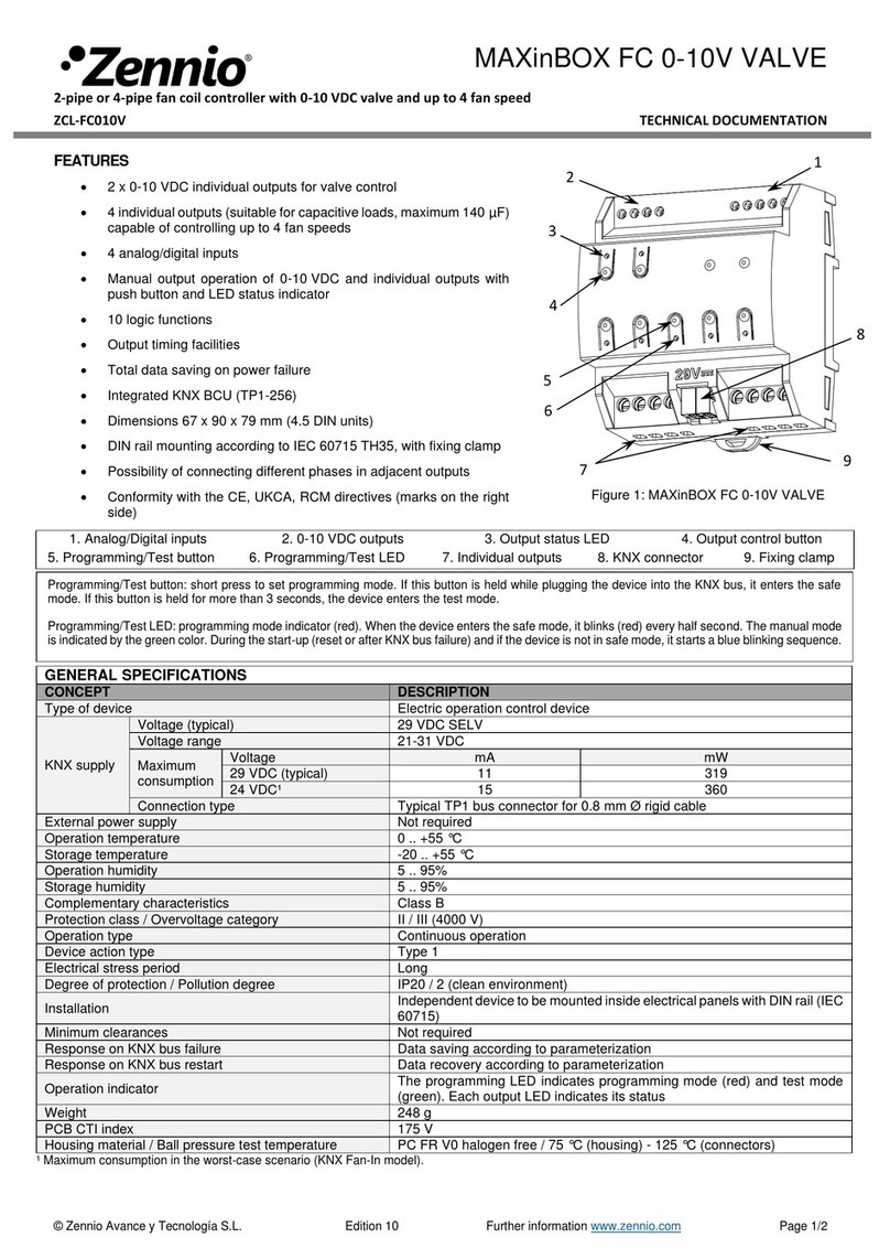
Zennio Analog User manual

Fan Coil ‘Analog’
https://www.zennio.com Technical Support: https://support.zennio.com
2
CONTENT
Content.......................................................................................................................................... 2
1 Introduction .......................................................................................................................... 3
2 Configuration......................................................................................................................... 4
2.1 Configuration.................................................................................................................... 4
2.2 Fan Coil X.......................................................................................................................... 4
2.2.1 Valve ......................................................................................................................... 7
2.2.2 Fan .......................................................................................................................... 11
2.2.3 Initialisation ............................................................................................................ 14
ANNEX I. Automatic Air Recirculation in Cooling Mode.............................................................. 16

Fan Coil ‘Analog’
https://www.zennio.com Technical Support: https://support.zennio.com
3
1INTRODUCTION
A variety of Zennio devices incorporate the ‘Analog’ Fan Coil control module, which
enables the control external fan coil units where both the opening of the valves and the
fan speed can be controlled through analog voltage outputs.
The fan coil units to be controlled may be two-pipe or four-pipe. Each pair of pipes
constitute a water circuit controlled by a valve, whose position is managed by a 0 –10
VDC analogue signal.
Typically, the two water circuits of a four-pipe fan coil unit correspond to the cooling and
heating functions, being therefore both modes available during the device operation.
The single water circuit of a two-pipe fan coil unit, on the other and, may be configured
for cooling, heating or both.
Important: In order to confirm whether a particular device or application program
incorporates the fan coil analog function, please refer to the device user manual, as
there may be significant differences between the functionality of each Zennio device.
Moreover, to access the proper fan coil analog user manual, it is always recommended
to make use of the specific download links provided at the Zennio website
(www.zennio.com) within the section of the specific device being parameterised.

Fan Coil ‘Analog’
https://www.zennio.com Technical Support: https://support.zennio.com
4
2CONFIGURATION
Please note that the screenshots and object names shown next may be slightly different
depending on the device and on the application program.
2.1 CONFIGURATION
After enabling the module, in the general configuration of the device, the "Fan Coil" tab
will be available in the ETS tab tree. In this tab, a box will be provided for each fan coil,
in order to configure them independently. Refer to the specific application program
manual to identify where these boxes are located.
ETS PARAMETERISATION
Figure 1. Fan Coil - Configuration
Fan Coil X [disabled/enabled]: enables the “Fan Coil X” tab in the left menu
(see section 2.2).
2.2 FAN COIL X
In this tab, the generic characteristics of the fan coil unit to be controlled are configured.
Among them, the type of fan coil of the installation must be selected:
A four-pipe fan coil unit, which requires the simultaneous management of two
independent circuits (one for heating and one for cooling).
A two-pipe fan coil unit, which requires the management of a single circuit (for
heating, for cooling or for both).

Fan Coil ‘Analog’
https://www.zennio.com Technical Support: https://support.zennio.com
5
In addition to the type of fan coil and the type of control, the general configuration
includes the following options:
Mode change minimum time: in cases where the fan coil has both heating and
cooling modes, a minimum time can be selected to ensure that the mode change
is carried out safely. This time will be applied between the fan deactivation and
the valve of the new mode opening.
Figure 2 shows the above, based on operation in cooling mode operation and after
receiving the command to switch to heating mode:
Figure 2. Minimum time for mode change
Fan coil always on: a communication object can be provided for the switch-on
and the switch-off of the fan coil control module, aswell as its corresponding status
object. Alternatively, it is possible to configure the module to maintain the fan coil
control permanently switched on.
Automatic Air Recirculation in Cooling Mode: sets whether in the cooling mode
the fan should remain on (thus improving the user comfort) even when the valve
is closed. See ANNEX I. Automatic Air Recirculation in Cooling Mode.
Initialization: enables to configure the behaviour of the 'Analog' fan coil module
after a bus fault or an ETS download. See section 2.2.3.
Heating
Heating (status)
Cooling Valve = 0
Fan = 0
Heating valve > 0
Fan > 0
Mode Change
Minimum Time

Fan Coil ‘Analog’
https://www.zennio.com Technical Support: https://support.zennio.com
6
ETS PARAMETERISATION
After enabling the Fan Coil X, in the "Configuration" tab (see section 2.1), a new tab of
the same name is added to the left tree.
Figure 3. Fan Coil X - General Configuration.
Type of Fan Coil [2 Pipes / 4 Pipes].
Mode (only available for “2 Pipes”fan coil unit) [Heating / Cooling / Cooling +
Heating].
For fan coil of "4 Pipes" or "2 Pipes" with "Cooling + Heating" mode active, there
will be the one-bit object “[FCn] Mode”for the selection of the desired mode, as
well as the corresponding status object “[FCn] Mode (Status)”.
Mode Change Minimum Time (only available for fan coil of "4 Pipes" or "2 Pipes"
with "Cooling + Heating" mode active) [[0…3600][s] / [0…1440][min] / [0…24][h]]:
time that will elapse from fan deactivation to the opening of the new mode valve.
Fan Coil Always On [disabled/enabled]: configures the module to maintain the
fan coil control permanently switched on. If disabled, the objects “[FCn] On/Off”
and “[FCn] On/Off (Status)”will allow, respectively, to switch on/off the control
and to know its status.
Automatic Air Recirculation in Cooling Mode [disabled/enabled]: sets whether
in the Cooling modethe fan should remain on, even when the valve is closed. See
ANNEX I. Automatic Air Recirculation in Cooling Mode.
➢Fan Speed [0…20…100][%]: speed that the fan will reach when the air
recirculation is activated. This speed can be modified through the object
"[FCx] Fan: Automatic Air Recirculation Speed".

Fan Coil ‘Analog’
https://www.zennio.com Technical Support: https://support.zennio.com
7
Initialization [Default / Custom]: enables configuration of the behaviour of the Fan
Coil 'Analog' module after a bus failure or an ETS download. If the "Custom" option
is selected, the "Initialization" sub-tab is enabled. See section 2.2.3.
2.2.1 VALVE
This section details the valve settings that are common for both modes, heating or
cooling. The control signal characteristics and limits can be configured, and an anti-seize
protection can be enabled for each valve.
Control signal scaling: adjusts the valve control signal (OV) by means of a
scaling function of the input control signal (IV), with different settings for cooling
and heating configurations.
The output control value (OV), resulting from the scaling function, is defined by
the following variables:
➢Input control value (IV): control value received from the thermostat. The
objects that will store this value will be "[FCx] Control Variable (Heating)"
and "[FCx] Control Variable (Cooling)".
➢Minimum/Maximum input value (X1 / X2): values of the input control
signal which determine from which value the valve shall start to open and
from which value the valve is considered fully open. For values below the
minimum the valve will remain closed and values above the maximum will
be ignored, as the valve is considered to be already open.
➢Minimum/Maximum output value (Y1 / Y2): valve control values
determining minimum and maximum opening percentages. These are
specific characteristics of each valve.
OV
IV
Y2
Y1
X1
X2

Fan Coil ‘Analog’
https://www.zennio.com Technical Support: https://support.zennio.com
8
The objects that will store the output control value, "[FCn] Valve: Control" (for
fan coil of two pipes) and "[FCn] Cooling Valve: Control" and "[FCn] Heating
Valve: Control" (for fan coil of four pipes), must be linked to the appropriate
actuator.
Example: 2-10V valve which, for installation reasons, is configured:
Y1 = 10%
Minimum valve opening value.
Y2 = 75%
Maximum valve opening value.
X1 = 33%
Minimum regulation value for the valve to start opening.
X2 = 66%
Control value at which the valve is considered fully open (in this case
75%).
oWith an input value (VE) of 20%, the valve does not open. Minimum input regulation
value 33%.
oWith an input value (VE) of 40%, the valve outlet value (VS) will be 23.8%.
oWith an input value (VE) of 70%, the valve outlet value (VS) will be 75%.
Control signal change limits: prevents damage to the valve due to small
changes in its position and/or permanent activation of the valve.
Anti-seize protection: automatic and independent functionality for each valve,
which prevents the valves from remaining in afixed position, either open orclosed,
for longer than the configured time. Every time the anti-seize period expires, the
valve will automatically switch to the inverse position, remaining at it until the
execution time ends. After that, the valve will recover the previous state or, if a
control or mode change command has been received during the run, to the
corresponding position.
Note: For safety reasons, if 4 pipes are configured and the anti-seize protection is
initiated on the cooling when it is closed and the heating valve is open, then both
will change their status avoiding having both valves open at the same time.

Fan Coil ‘Analog’
https://www.zennio.com Technical Support: https://support.zennio.com
9
ETS PARAMETERISATION
This section includes all parameters related to the configuration of the cooling and
heating valves.
Figure 4. Fan Coil - Cooling/Heating Valve: Control Signal Scaling.
The parameters are the following:
Control Signal Scaling
➢Minimum Input Value (X1) [0…100][%]: defines the minimum regulation
value to be received from the thermostat that will cause the valve to start
opening.
➢Maximum Input Value (X2) [0…100] [%]: defines the maximum regulation
value to be received from the thermostat that will cause the maximum
opening of the valve.
➢Minimum Output Value (Y1) [0…100] [%]: defines the minimum operating
value of the valve at which it will start to open.

Fan Coil ‘Analog’
https://www.zennio.com Technical Support: https://support.zennio.com
10
➢Maximum Output Value (Y2) [0…100] [%]: defines the maximum operating
value of the valve, maximum opening position.
Note: If, as a result of a parameterisation error, the minimum value of the control
signal (input or output) isgreater than amaximum value, 0% (minimum) and 100%
(maximum) will be taken as control signal scaling range.
Control Signal Change Limits
➢Minimum Change between Output Signals [0…5…100][%]: minimum
increase or decrease in the output signal value with respect to the last value
that caused a change in the valve position.
➢Minimum Time between Output Signals [[0…10…3600][s] /
[0…1440][min]]: minimum time that must elapse since the last action that
caused a change in valve position.
Notes:
•The parameter minimum change between output signals is not
considered if the command involves a change to the maximum value, or
a closing of the valve.
•These two parameters, minimum change and minimum time between
output signals, must be met simultaneously for the control signal to be
sent to the valve.
Anti-Seize Protection
➢Anti-Seize Protection [disabled/enabled]: enables or disables the valve
anti-seize protection function, and with it the objects "[FCx] Cooling Valve:
Anti-Seize Protection (Status)" and "[FCx] Heating Valve: Anti-Seize
Protection (Status)", which will take the value "1" when the function is
running or "0" otherwise.
•Periodicity [1…7…255][day(s)]: defines the maximum time that the
valve can remain in the same position.
•Duration [1…5…255][min]: defines the run time of the anti-seize
protection. During this time the valve will remain in the opposite position.

Fan Coil ‘Analog’
https://www.zennio.com Technical Support: https://support.zennio.com
11
2.2.2 FAN
The fan features an automatic control, in which its speed is calculated by the module
itself and an external reference, and a manual control, in which the fan speed will be
controlled externally. For both modes the fan speed will always comply a minimum and
a maximum allowed speed.
When both, the manual and the automatic control modes are enabled, a communication
object will let switching from one control mode to the other, although the receipt of a
manual command would itself trigger the switch to manual mode. In addition, it is
possible to set in parameters which of the two control modes must be active after
download, and also a time-out counter to return to automatic mode after a period of
time without receiving manual commands.
On the other hand, a delay to activate and deactivate fan can be defined for each
operating mode. These delays will establish how much time must elapse from the arrival
of the controlsignal fromthe valve that generates the fan on or off, until theoutput control
command is sentto thefan. If there is a parameterised minimum time for mode change
(see section 2.2), this delay will be applied together with the fan on and off delays as
follows:
Figure 5. Delay for fan activation/deactivation.
Heating
Heating (status)
Cooling Valve = 0
Fan = 0
Delay to deactivate
fan (Cooling)
Heating Valve > 0
Mode change
minimum time
Fan > 0
Delay to actívate
fan (Heating)

Fan Coil ‘Analog’
https://www.zennio.com Technical Support: https://support.zennio.com
12
ETS PARAMETERISATION
Figure 6. Fan Coil - Fan.
Control Mode [Automatic / Manual / Automatic + Manual]. If “Automatic + Manual”
is selected, the parameters corresponding to the mode change are displayed:
➢Mode after ETS Download [Automatic / Manual].
➢Mode Object Polarity [0 = Automatic; 1 = Manual / 0 = Manual; 1 =
Automatic]: sets the polarity of the object that enables switching from one
control mode to another ("[FCx] Fan: Manual/Automatic"), as well as its
status object ("[FCx] Fan: Manual/Automatic (Status)").
➢Return to Automatic Mode after Period of Time [disabled/enabled].
Enabling this functionality displays the parameters for its configuration:
•Manual Control Duration [0…30…1440][min] / [0…24][h]. If, after this
time, the fan has not received any new manual control command ("[FCx]
Manual Fan: Speed"), the automatic control mode will be restored. This

Fan Coil ‘Analog’
https://www.zennio.com Technical Support: https://support.zennio.com
13
time can be modified through the object "[FCx] Manual Fan: Manual
Control Duration".
Fan Speed Control.
An input signal to control the fan coil generates an output value according to the
following parameterisable limits:
➢Minimum value [1...20...100][%]. For any inputcontrol value that causes an
output lower than this limit, the output will be equal to the minimum value.
Note:
•For an input value 0, the output will be equal to 0, so the fan will be
deactivated, except when automatic air recirculation is applied in cooling
mode (see ANNEX I. Automatic Air Recirculation in Cooling Mode).
•If the control command received involves fan deactivation but opens the
valve, the fan will be set to the minimum value.
➢Maximum Value [1...100] [%]: maximum value allowed so that, for any input
control value that causes an output higher than this limit, the generated
output will be equal to the maximum value.
The generated output value will be sent to the communication object "[FCx] Fan:
Speed Control".
These limits also apply to manual fan speed control when through the "[FCx]
Manual Fan: Speed" object.
Activation delay
For each operating mode (cooling and heating) there will be the following
parameters:
➢Delay to Activate Fan [[0…3600][s] / [0…1440][min] / [0…24][h]]: time that
will elapse from the arrival of the control signal that turns on the fan to the
sending of the order that will make the activation effective.
➢Delay to Deactivate Fan [[0…3600][s] / [0…1440][min] / [0…24][h]]: time
from the arrival of the control signal that will turn off the fan, until the order
to fan deactivation is sent.

Fan Coil ‘Analog’
https://www.zennio.com Technical Support: https://support.zennio.com
14
2.2.3 INITIALISATION
The fan coil ‘Analog’ function module after ETS download, and for safety reasons, will
always initialise off. After a bus failure the module,by default, will keep its previous state.
This tab offers the possibilityto configure the initialization of the Fan Coil 'Analog' module
by defining aspects such as its initial state or whether an update of the input objects
and/or the sending of certain status objects is required after start-up.
If the input objects update functionality is enabled, the objects on which read requests
for update will be sent will be:
"[FCx] On/Off".
"[FCx] Mode".
"[FCx] Control Variable (Heating/Cooling)".
"[FCx] Fan: Manual/Automatic".
"[FCx] Manual Fan: Speed".
"FCx] Manual Fan: Manual Control Duration".
If, for the purpose of updating other devices in the system the status sending start-up
is enabled, the available status objects can be additionally selected to be sent:
"[FCx] On/Off (status)".
"FCx] Mode (status)".
"FCx] Fan: Manual/Automatic (Status)".
ETS PARAMETERISATION
After selecting the "Custom" option, in the Initialization parameter, in the "Fan Coil X"
tab (see section 2.2), a new tab of the same name is added to the left tree.
Figure 7. Fan Coil - Initialization.

Fan Coil ‘Analog’
https://www.zennio.com Technical Support: https://support.zennio.com
15
Initial Status [Previous / Off]. If “Previous” is selected, the status before the failure
status shall be maintained, except after programming, in which case the output
will be off.
Input Objects Update [disabled/enabled]: if enabled, a reading of the input
objects will be carried out after a bus fault or ETS download. The read requests
will start to be sent after the parameterized delay ([0...600][s]).
Send Status Object [disabled/enabled]: if enabled, several checkboxes will be
displayed to indicate the objects to be sent.
➢On/Off [disabled/enabled]. Available if the Fan Coil Always On parameter
(section 2.2) is disabled.
➢Mode [disabled/enabled]. Available if the selected type of fan coil is "4
Pipes" or "2 Pipes" with the "Cooling + Heating" mode active (see section
2.2).
➢Fan: Automatic/Manual [disabled/enabled]. Available if the fan control
mode selected for the fan is "Automatic + Manual" (see section 2.2.2).
The statuses will start to be sent after the parameterized delay [0...600][s].

Fan Coil ‘Analog’
https://www.zennio.com Technical Support: https://support.zennio.com
16
ANNEX I. AUTOMATIC AIR RECIRCULATION IN
COOLING MODE
If this function automatic air recirculation in cooling mode is activated and the system
is operating in cooling mode:
When the valve is closed, the fan must remain on or switch on.
In case the input control command is lower than the minimum value to activate
the valve, the fan speed will be the value specified by parameter and modifiable
by object “[FCn] Fan: Automatic Air Recirculation Speed”.
Once recirculation is active, events such as fan coil deactivation, a mode change or a
bus failure can force the fan to stop.
Whereas, if automatic air recirculation in cooling mode is not enabled or the system
is operating in heating mode:
When receiving a control command lower than the value that activates the valve,
both the valve and the fan will take a value of 0%.
The Table 1 below shows the specific effects of having or not having the automatic air
recirculation function enabled in different situations. The table is generated starting with
the valve closed.
Speed Control
Automatic
Recirculation
Current Mode
Implications
Valve
Fan
Automatic
Enabled
Heating
Closed
Switch Off
Cooling
Closed
Recirculation
Disabled
Heating
Closed
Switch Off
Cooling
Closed
Switch Off
Manual
Enabled
Heating
Closed
Switch Off
Cooling
Closed
Manual
Disabled
Heating
Closed
Switch Off
Cooling
Closed
Switch Off
Table 1. Automatic Air Recirculation.
Table of contents
Other Zennio Control Unit manuals
Popular Control Unit manuals by other brands

Acces I/O products
Acces I/O products ETH-IIRO-16 Series user manual

QTS
QTS AN-X4-ABRIO-HMI user manual

Siemens
Siemens SIDOOR AT40 System manual

Genebre
Genebre 2220 Installation, operation and maintenance manual

Vag
Vag GA INDUSTRIES Figures 251-D Installation, operation and maintenance manual

TLV
TLV V1P Series manual