manuals.online logo
Brands
  1. Home
  2. •
  3. Brands
  4. •
  5. Zennio
  6. •
  7. Control Unit
  8. •
  9. Zennio GetFace IP User manual

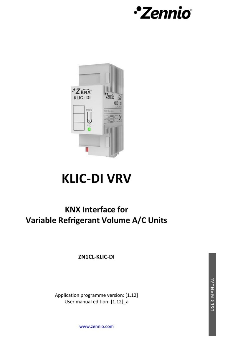
Zennio GetFace IP User manual


GetFaceIP
Surfaceinstallation‐Frame‐1module
ZVP‐CB1M
Assemblyinstructions


©ZennioAvanceyTecnologíaS.L.Ed.2Formoreinfowww.zennio.com
Page 1 / 1
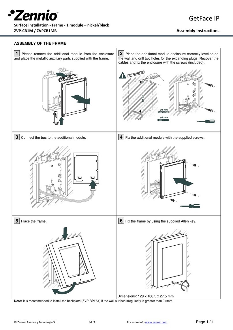
ASSEMBLY OF THE FRAME
1 Please remove the additional module from the enclosure
and place the metallic auxiliary parts supplied with the frame.
2 Place the additional module enclosure correctly levelled on
the wall and drill two holes for the expanding plugs. Recover the
cables and fix the enclosure with the screws (included).
3 Connect the bus to the additional module.
4 Fix the additional module with the supplied screws.
5 Place the frame.
6 Fix the frame by using the supplied Allen key.
Note: It is recommended to install the backplate (ZVP-BPLA1) if the wall surface irregularity is greater than 0.5mm.
Dimensions: 128 x 106.5 x 27.5 mm

GetFaceIP
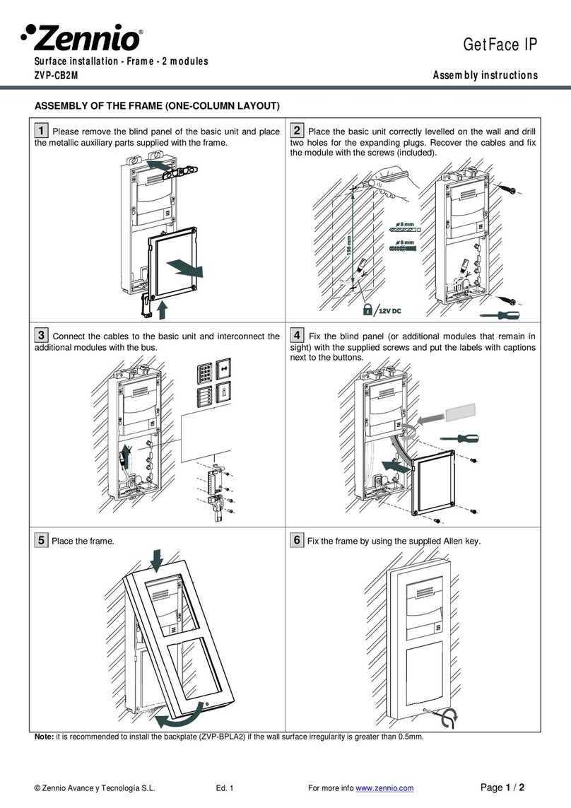
Surfaceinstallation‐Frame‐2modules
ZVP‐CB2M
Assemblyinstructions


©ZennioAvanceyTecnologíaS.L.Ed.2Formoreinfowww.zennio.com
Page 1 / 2
ASSEMBLY OF THE FRAME (ONE-COLUMN LAYOUT)
1 Please remove the blind panel of the basic unit and place
the metallic auxiliary parts supplied with the frame.
2 Place the basic unit correctly levelled on the wall and drill
two holes for the expanding plugs. Recover the cables and fix
the module with the screws (included).
3 Connect the cables to the basic unit and interconnect the
additional modules with the bus.
4 Fix the blind panel (or additional modules that remain in
sight) with the supplied screws and put the labels with captions
next to the buttons.
5 Place the frame.
6 Fix the frame by using the supplied Allen key.
Note: it is recommended to install the backplate (ZVP-BPLA2) if the wall surface irregularity is greater than 0.5mm.
Dimensions:
232 x 106.5 x 27.5 mm
©ZennioAvanceyTecnologíaS.L.Ed.2Formoreinfowww.zennio.comPage 2 / 2
ASSEMBLY OF THE FRAME (MULTIPLE-COLUMN LAYOUT)
1 Please remove the blind panels and the additional
modules. After that, assemble the additional module enclosures
by opening the gaps previously. Then, fix the assembly by using
the supplied parts and screws. Place the metallic parts supplied
with the frame.
2 Place the left assembly correctly levelled on the wall and
drill two holes for the expansive plugs. Recover the cables and
fix the module with the screws (included).
3 Place the right assembly on the wall by using the T-shape
parts. Mark the position of the holes, drill them and afterwards
place an expansive plug inside them.
4 Fix the right assembly to the wall with screws. Make the
connections of the basic unit and prepare the additional
modules. Pass the bus cable through the gaps.
5 Interconnect the additional modules with the bus as
indicated in the schema and then fix the additional modules with
screws.
6 Place the frames and fix them by using the supplied Allen
key.
Note: it is recommended to install the backplate (ZVP- BP2W2H) if the wall surface irregularity is greater than 0.5mm.
2x

GetFaceIP
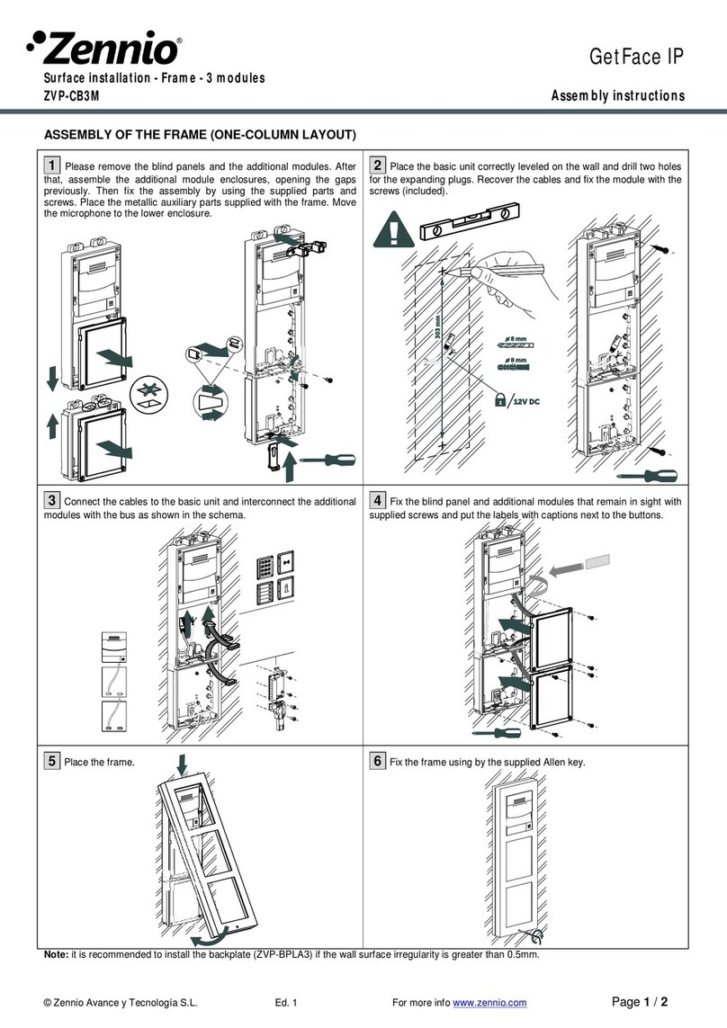
Surfaceinstallation‐Frame‐3modules
ZVP‐CB3M
Assemblyinstructions


©ZennioAvanceyTecnologíaS.L.Ed.2Formoreinfowww.zennio.com
Page 1 / 2
ASSEMBLY OF THE FRAME (ONE-COLUMN LAYOUT)
1
Please remove the blind panels and the additional modules. After
that, assemble the additional module enclosures, opening the gaps
previously. Then fix the assembly by using the supplied parts and
screws. Place the metallic auxiliary parts supplied with the frame. Move
the microphone to the lower enclosure.
2
Place the basic unit correctly leveled on the wall and drill two holes
for the expanding plugs. Recover the cables and fix the module with the
screws (included).
3
Connect the cables to the basic unit and interconnect the additional
modules with the bus as shown in the schema.
4
Fix the blind panel and additional modules that remain in sight with
supplied screws and put the labels with captions next to the buttons.
5
Place the frame.
6
Fix the frame using by the supplied Allen key.
Note: it is recommended to install the backplate (ZVP-BPLA3) if the wall surface irregularity is greater than 0.5mm.
Dimensions:
337 x 106.5 x 27.5 mm
©ZennioAvanceyTecnologíaS.L.Ed.2Formoreinfowww.zennio.comPage 2 / 2
ASSEMBLY OF THE FRAME (MULTIPLE-COLUMN LAYOUT)
1 Please remove the blind panels and the additional modules. After
that, assemble the additional module enclosures by opening the gaps
previously. Then, fix the assembly by using the supplied parts and
screws. Place the metallic parts supplied with the frame. Move the
microphone to the lower enclosure.
2 Place the left assembly correctly leveled on the wall and drill two
holes for the expansive plugs. Recover the cables, place the bus and fix
the left assembly with the screws (included).
3 Place the right assembly on the wall by using the T-shape parts.
Mark the position of the holes, drill them and afterwards place
expansive plugs inside.
4 Fix the right assembly to the wall with screws. Make the
connections of the basic unit and prepare the additional modules. Pass
the bus cable through the gaps.
5 Interconnect the additional modules with the bus as indicated in the
schema and then fix the additional modules with the screws.
6 Place the frames and fix them by using the supplied Allen key.
Note: it is recommended to install the backplate (ZVP-BP2W3H, ZVP- BP3W3H) if the wall surface irregularity is greater than 0.5mm.
4x

This manual suits for next models

1

Other Zennio Control Unit manuals

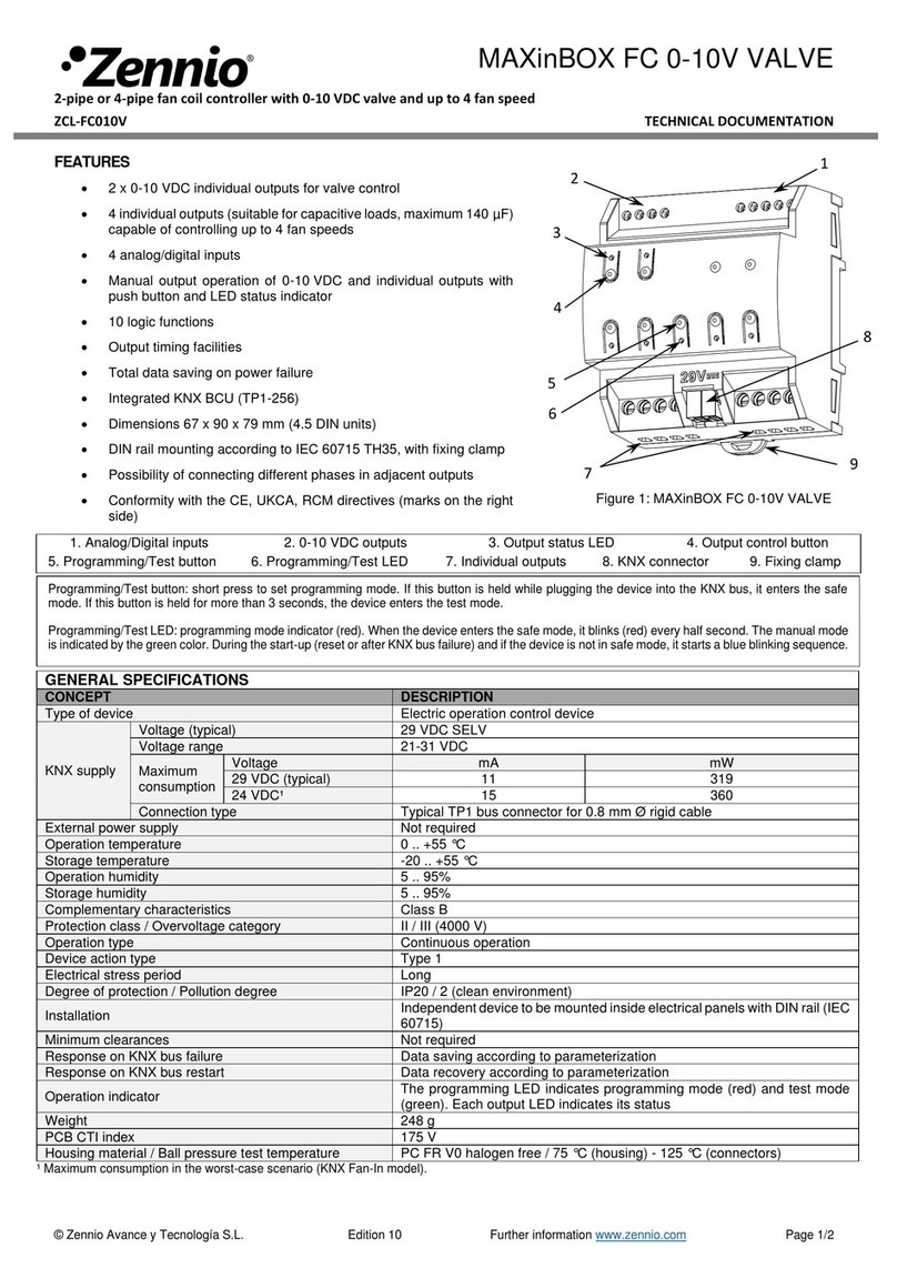
Zennio KLIC-DI User manual

Zennio

Zennio KLIC-DI User manual

Zennio ZVPCB1MB User manual

Zennio

Zennio ZVPCB1MB User manual

Zennio MAXinBOX FC Guide

Zennio

Zennio MAXinBOX FC Guide

Zennio ZVP-CB2M User manual

Zennio

Zennio ZVP-CB2M User manual

Zennio GetFace IP ZVP-CB3M User manual

Zennio

Zennio GetFace IP ZVP-CB3M User manual

Zennio MINiBOX 0-10V X3 Guide

Zennio

Zennio MINiBOX 0-10V X3 Guide

Zennio Analog User manual

Zennio

Zennio Analog User manual

Popular Control Unit manuals by other brands

RADWAG MW-01 Series user manual

RADWAG

RADWAG MW-01 Series user manual

Burkert 3232 operating instructions

Burkert

Burkert 3232 operating instructions

De Nora Capital Controls 1041B Series instruction manual

De Nora

De Nora Capital Controls 1041B Series instruction manual

XtendLan DPA-MEM user manual

XtendLan

XtendLan DPA-MEM user manual

SICK CDM420-0001 Fitting instructions

SICK

SICK CDM420-0001 Fitting instructions

Koheron CTL101 Series user guide

Koheron

Koheron CTL101 Series user guide

Nederman TAV 50 Series instruction manual

Nederman

Nederman TAV 50 Series instruction manual

Sanhua RFKA Series instructions

Sanhua

Sanhua RFKA Series instructions

roco multiMAUSPRO Getting started

roco

roco multiMAUSPRO Getting started

Watts LFM127-8 Installation, operation and maintenance

Watts

Watts LFM127-8 Installation, operation and maintenance

DITEC DAS200T quick reference

DITEC

DITEC DAS200T quick reference

Sentiotec Infrabox basic S Instructions for installation

Sentiotec

Sentiotec Infrabox basic S Instructions for installation

Baker Hughes Masoneilan Instructions for installation

Baker Hughes

Baker Hughes Masoneilan Instructions for installation

Burkert 2301 Series quick start

Burkert

Burkert 2301 Series quick start

Allen-Bradley Entek XM-123 user guide

Allen-Bradley

Allen-Bradley Entek XM-123 user guide

Hugo Lahme FitStar 577387 user manual

Hugo Lahme

Hugo Lahme FitStar 577387 user manual

Panasonic CA-RC3000EU operating instructions

Panasonic

Panasonic CA-RC3000EU operating instructions

NexDome 2.2m Dome Rotation Kit Installation and operation manual

NexDome

NexDome 2.2m Dome Rotation Kit Installation and operation manual

manuals.online logo
manuals.online logoBrands
  • About & Mission
  • Contact us
  • Privacy Policy
  • Terms and Conditions

Copyright 2025 Manuals.Online. All Rights Reserved.