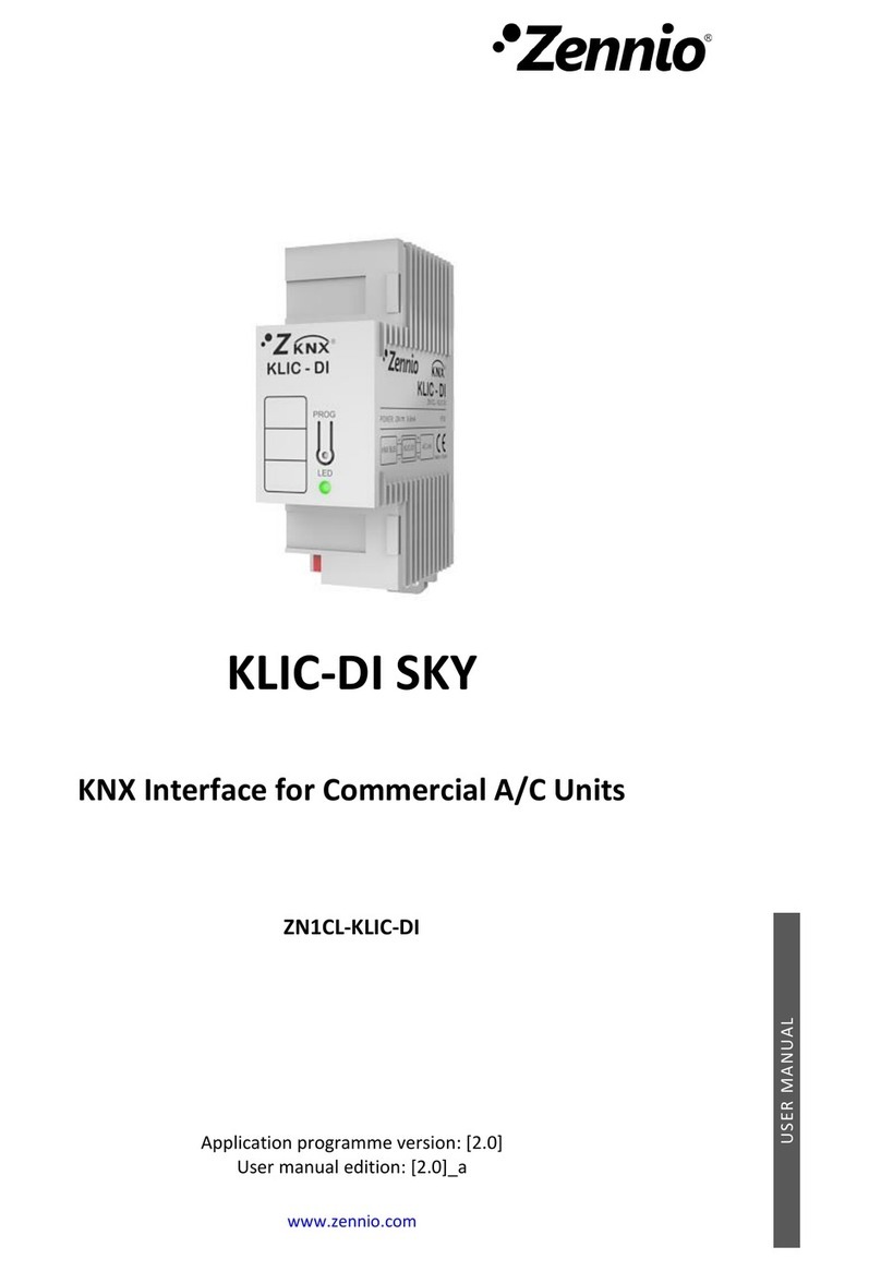
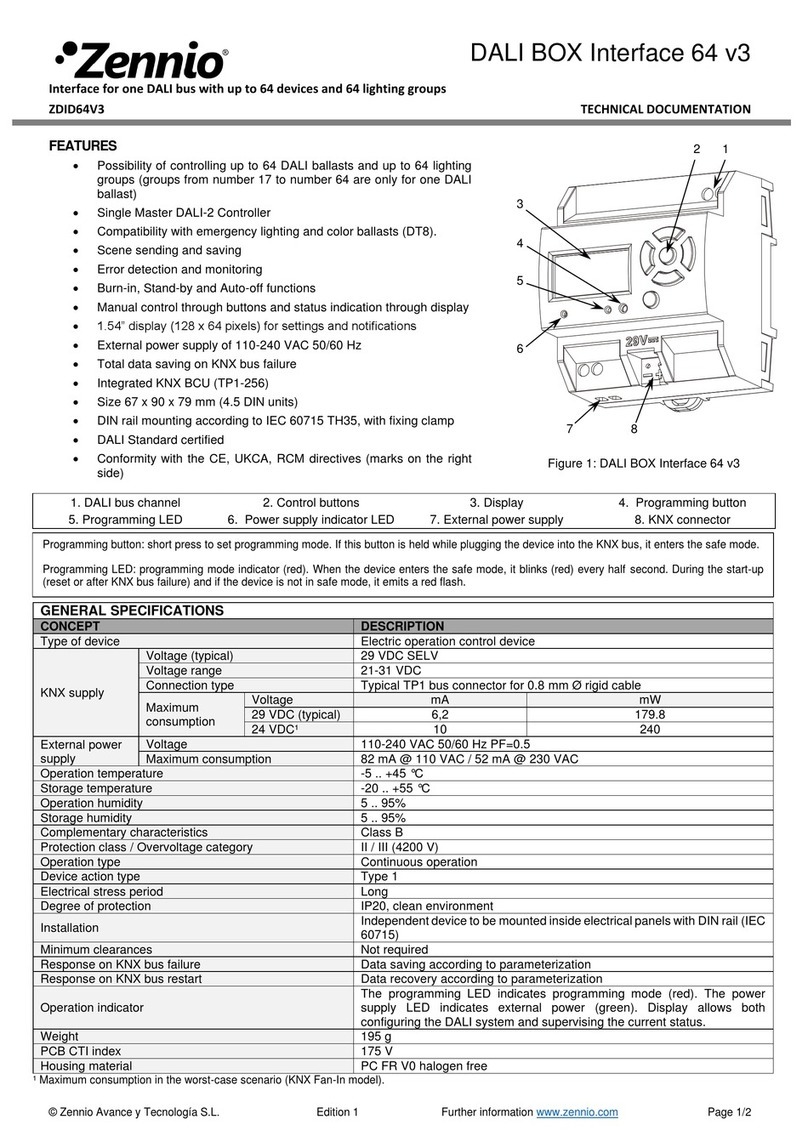
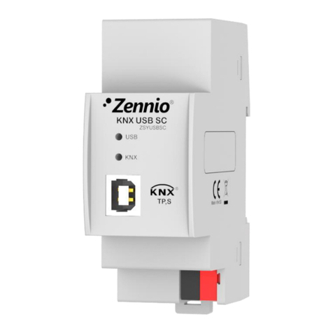
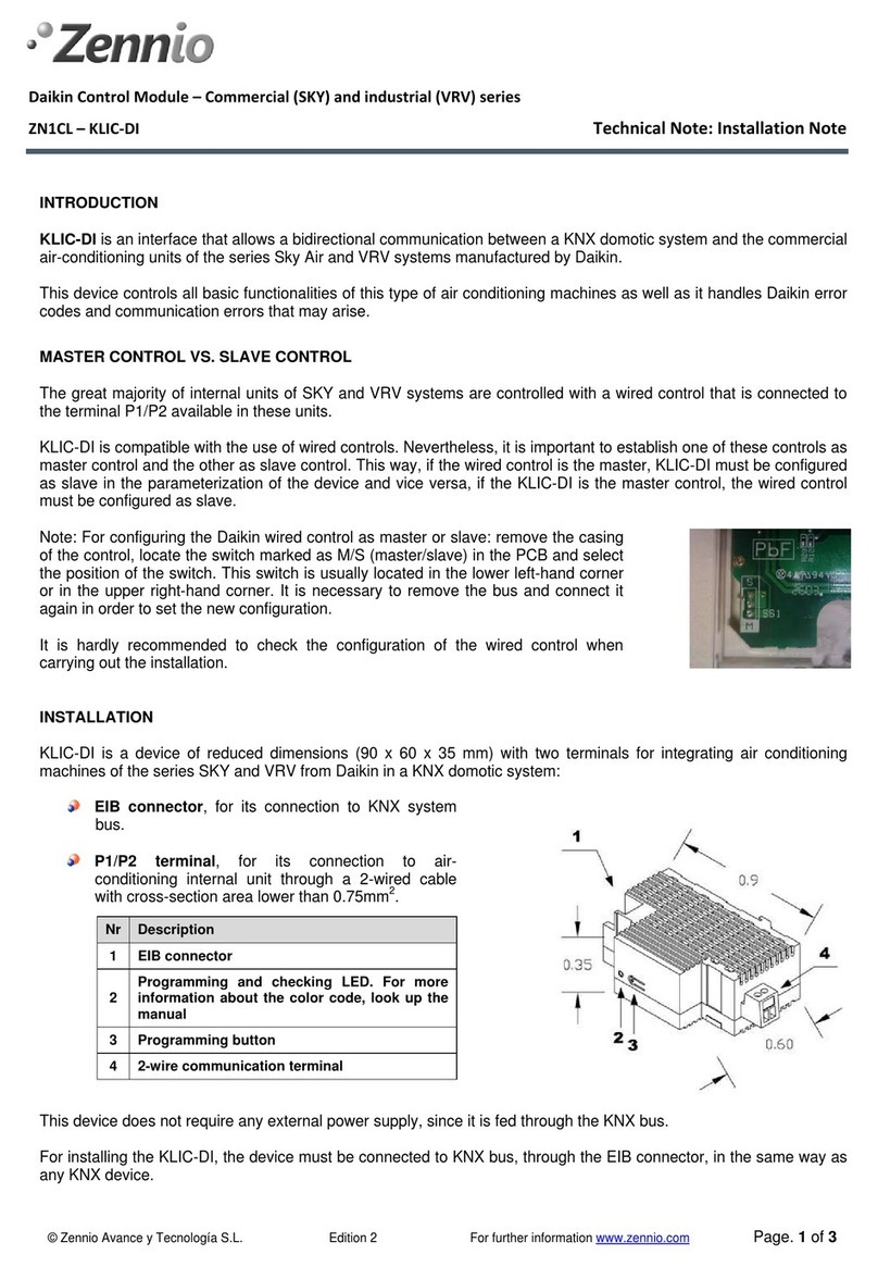
Zennio KLIC-DI User manual

KLIC-DI
INTERFACE KNX – DAIKIN
ZN1CL-KLIC-DI
Edition 4.0
Version 1.4
PRODUCT MANUAL

ZENNiO AVANCE Y TECNOLOGÍA www.zennio.com
2
Index
1. Introduction ............................................................................................................ 3
2. Installation .............................................................................................................. 5
2.1. KLIC-DI Installation ......................................................................................... 5
2.2. Elements Description ......................................................................................
3. Configuration .......................................................................................................... 8
3.1. Basic Control .................................................................................................. 8
3.2. Advanced Functionalities ................................................................................ 8
4. Parameterization .................................................................................................. 12
4.1. Default Configuration .................................................................................... 12
4.2. General ......................................................................................................... 14
4.3. Mode ............................................................................................................. 15
4.4. Fan speed ..................................................................................................... 15
4.5. Scenes .......................................................................................................... 17
4. . Temperature Limitation ................................................................................. 18
4.7. Automatic switch off ...................................................................................... 19
4.8. Errors management ...................................................................................... 19
4.9. Initial configuration ........................................................................................ 20
Annex I. Communication Objects ................................................................................ 22
Annex II. Correspondence Error Codes of Daikin Units ............................................... 24

ZENNiO AVANCE Y TECNOLOGÍA www.zennio.com
3
1. INTRODUCTION
The KLIC-DI is an interface that allows a bidirectional communication between a
KNX domotic system and the commercial air-conditioning units of the series Sky Air
manufactured by Daikin.
Due to this bidirectional communication, the air conditioning unit can be controlled
in the same way that using an IR remote controller and the real status of the air-
conditioning unit is checked and sent to the KNX bus for its monitoring.
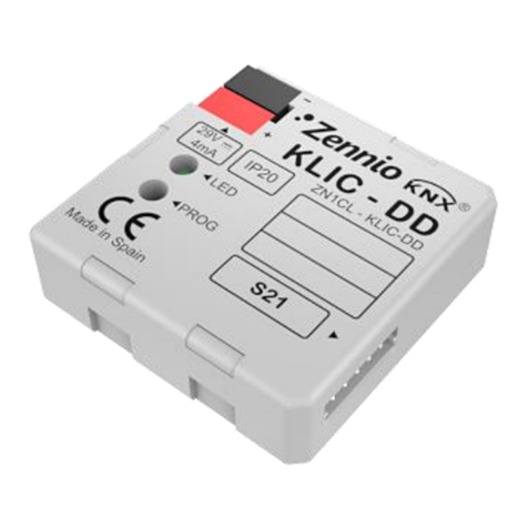
Figure 1 KLIC-DI
In case of using a wired remote control in the same communication bus of the unit,
the KLIC-DI will communicate with this remote control acting one device as master
control while the other device will act as slave control. It is important to verify that the
KLIC-DI and the wired remote control are configured with different type of control. This
way, the control acting as slave will update its status when the master orders it and will
communicate its status changes when they are modified from the own slave control.
Device Feature :
Small enclosure: 90 x 0 x 35 mm (2 DIN rail units)
Designed to be installed inside distribution boxes or electrical mounting boxes.
KLIC-DD controls commercial and industrial air conditioners (bi-directional
communication) of the series Sky Air and VRV from Daikin.
Daikin control protocol.

ZENNiO AVANCE Y TECNOLOGÍA www.zennio.com
4
Control over all Daikin air-conditioning functionality. Error management handles
Daikin error codes as well as any communication errors that may arise.
LED indicators allow monitoring of the bidirectional traffic flow.
Integrated EIB/KNX Bus Coupling Unit.
Complete data saving in case of Bus Power Failure.
CE Compliant

ZENNiO AVANCE Y TECNOLOGÍA www.zennio.com
5
2. INSTALLATION
2.1. KLIC-DI INSTALLATION
The KLIC-DI installation is performed the same way that any other KNX device. We
just need to connect the device to KNX bus through the specific KNX connector.
On the other hand, this device is connected to the Daikin internal unit PCB (P1/P2
connectors), using a 2-wire cable.
If the wired remote control from Daikin is also used, it is necessary to make sure
that the wired remote control is in mode slave if the KLIC-DI is configured as master
control. And vice versa, if the KLIC-DI is configured as slave control, the wired remote
control must be in master position.
Once the device is provided with power supply from the bus, both, the physical
address and the KLIC application program can be downloaded.
This device does not need any external supply, since it just works with the power
supply of KNX bus.
Connection to daikin P1/P2 bu diagram
Figure
2
Connecting KLIC
-
DI to P1/P2 bu
DAIKIN

ZENNiO AVANCE Y TECNOLOGÍA www.zennio.com
2.2. ELEMENTS DESCRIPTION
Prog: To set the device programming mode. When initially pushed, after BUS
Powering, “secure mode” is set.
Led: Led “On” indicates programming mode. Led blinking every 0,5s, the
device is set in “secure mode”. It also indicates bidirectional communication
between KLIC-DI and Daikin unit.
Diagram Leyend
A KLIC – DI
B Daikin Wired remote control
C Daikin SKY or VRV unit
P1 - P2 Daikin connection bu
1 - 2 Zennio connection terminal
* The wired remote control mu t operate in the oppo ite mode to
KLIC-DI
Note
The model FDXS
‐
‐‐
‐
E i controlled by KLIC-DD ( ee data heet) becau e the internal
unit doe not have P1/P2 port.
Figure
3
Connecting KLIC
-
DI to bu P1/P2 with wired remote cont
r
ol
( lave
mode)
DAIKIN
DAIKIN

ZENNiO AVANCE Y TECNOLOGÍA www.zennio.com
7
Communication Cable: 2-wire cable, direct to PI/P2 connectors that can be
found at the PCB of the internal unit, or in the wired remote control.
Besides including the programming red LED (typical in any KNX device), the KLIC-
DI incorporates two more LEDs, blue and green ones, in order to inform about the
bidirectional communication between KNX and Daikin, resulting very useful in the
installation process.
Nº De cription
1 EIB
connector
2 Programming LED
3 Programming button
4 2-wire communication terminal

ZENNiO AVANCE Y TECNOLOGÍA www.zennio.com
8
3. CONFIGURATION
3.1. BASIC CONTROL
With KLIC-DI, the air conditioning unit can be monitored and controlled the same
way it is done with the wired remote control provided with the air conditioning unit.
By means of bus KNX, it can be controlled the following basic functionalities of the
air conditioning system:
ON/OFF of the air conditioning unit.
Setpoint Temperature. Between 1 and 32 ºC.
Operating Mode: Auto, Heat, Dry, Fan and Cool.
Fan Speed: 2 or 3 speed levels configuration. (Check out the available levels in
the Daikin unit)
These functionalities have associated a machine status, which is periodically sent
to KLIC-DI. When KLIC-DI receives a status different from the previous one from the
machine, it updates the status of the corresponding parameter in the bus KNX.
3.2. ADVANCED FUNCTIONALITIES
Besides the basic control over the air conditioning system, KLIC-DI offers other
advanced functionalities that give an added value with regard to the wired remote
control:
Scene Configuration: allows establishing a specific parameters
combination for the air conditioning machine.
Temperature Limitation: Daikin air conditioning systems are limited in
temperature (usually to the range 1 -32 ºC. Please verify the range for a
particular model in the corresponding Daikin manual). This KLIC
functionality allows configuring custom temperature ranges for the modes
Heat and Cool by means of the ETS in such a way that the setpoint
temperature will remain in the range. In case of receiving from the bus KNX
a temperature command with a value out of the configured limits, the
temperature value sent to the machine will be the corresponding limit value.

ZENNiO AVANCE Y TECNOLOGÍA www.zennio.com
9
Indoor temperature and Reference temperature: the Sky Air machines has
several temperature sensors for measuring the temperature in different internal
points.
The Indoor temperature is the measured internal value and it is used together
with the Reference temperature for controlling the modes Auto-Cool and Auto-
Heat of the air-conditioning machine.
The Reference temperature is the real temperature in the room to acclimatize.
It is necessary to communicate this parameter to the machine by means of the
corresponding communication object and it is hardly recommended to link this
communication object with a temperature sensor (installed in the room) which
periodically updates the temperature value.
The modes Auto-Heat and Auto-Cool can be controlled in three different ways
by the Daikin machine:
1. The machine receives the Reference temperature and, according to a
pre-configured hysteresis by the Daikin installer, it establishes the
corresponding auto mode.
2. The machine uses the Indoor temperature and, according to a pre-
configured hysteresis by the Daikin installer, it establishes the
corresponding auto mode.
3. The machine establishes the auto mode according to the average value
of the Reference temperature and the Indoor temperature.
The temperature value used by the machine in order to switch beatween the
Modes Auto-Cool and Auto-Cool depends on the configuration established in
the Dakin machine installation. This value, in any of the previous cases is
compared to the setpoint temperature in such a way that if the setpoint
temperature is higher the Auto-Heat mode is established and if the setpoint
temperature is lower than this value, the Auto-Cool is established.
Take into account: It is hardly recommended to link the Reference temperature to a
temperature sensor that periodically monitors the real temperature in the room
because the way of switching between the different Auto modes might not be known
and this fact can lead to a wrong functioning of the Auto mode. The Reference
temperature has a default value equal to 25ºC.
Auto Switch Off: allows temporarily switching off the machine if a status
change in the communication object associated to it, takes place. An
example of this functionality could be the use of a window sensor,
associated to the auto switch off, that allows switching off the machine if the
window is opened.
ZENNiO AVANCE Y TECNOLOGÍA www.zennio.com
1
0
Error Management: this functionality allows the sending of messages to
the bus informing about errors. Errors management handles Daikin error
codes as well as any communication errors that may arise
Besides informing about the apparition of possible errors it can be also
configured the sending of the error type.
In case of internal errors, the numerical code associated to the error type is
shown in the following table:
Error Number
Type of Internal Error
1 Problems with the data reception (speed, parity, etc.)
2 Communication waiting time exceeded (Time-out)
3 Incorrect checksum
4 Incorrect response from the machine
Regarding the numerical code associated to the external errors type, look
up the manual of the installed air-conditioning system or the Annex II
Correspondence Error Codes of Daikin Units.
Initial Configuration:
All machine status must have an initial value after installing the system or a
power failure. With this purpose, it has been included in the KLIC the
possibility of defining the initial status for the ON/OFF, temperature, fan and
speed of the machine.
These initial values can be sent both to the bus KNX and the air conditioning
unit.
Type of Control: Ma ter/Slave
It is important to take into account the type of control, master or slave, with
which the KLIC-DI is going to be configured.
The remote control “master” in the installation is in charge of the
communication with the machine and it will retransmit the instructions and
status between the machine and the slave remote control in case of having
one. In spite of the master/salve configuration, all the functionalities can be
set from both remote controls.
This functionality allows including in the installation both the KLIC-DI and the
Daikin wired control and choosing the desired master/slave configuration
whenever the KLIC-DI and the wired control are not configured with the

ZENNiO AVANCE Y TECNOLOGÍA www.zennio.com
1
1
same type of control. In case of having both controls configured as masters,
the screen of the Daikin control will show the error “88” and the error “U5”
will be sent to the bus.
Take into account: When switching the type of control of the Daikin wired
control between master and slave, it is necessary to remove the power
supply from the wired control and connecting it again for rebooting the wired
control in the suitable mode
Important: The wired control BRC1E51A7 can only operate as master
control. In case of using this model of wired control in the installation, it is
necessary configuring the KLIC-DI as slave control.

ZENNiO AVANCE Y TECNOLOGÍA www.zennio.com
1
2
4. PARAMETERIZATION
For starting to parameterize the device it is necessary, once the ETS has been
opened, importing the data base of the product KLIC-DI SKY 1.0.vd2.
Then the KLIC is added to the project where it is desired to include the device. Click
with the right mouse button the right button on the device and select “Edit
Parameters.. for starting with the configuration.
In the following sections there is a detailed explanation about each of the different
functionalities of the device in ETS.
4.1. DEFAULT CONFIGURATION
This section shows the default configuration from which the device configuration
starts.
If the window “Edit Parameters is opened for the first time, the KLIC General
configuration by default will be found.
Next figure shows the General window with the default values:
Figure
4
Default General Configuration

ZENNiO AVANCE Y TECNOLOGÍA www.zennio.com
1
3
As we can see in the previous figure all the advanced functionalities: scenes,
temperature limitation, auto switch off, errors management and initial configuration are
disabled by default.
If the Mode and Fan are selected, it will be seen that both the Individual Modes and
the Simplified Modes (Cool/Heat) are disabled by default while the Fan is configured for
2 different fan speeds and the step control is also disabled.
In the next figure, it can be watched the available communication object by
default: they allow sending the ON/OFF to the Split, setpoint temperature, mode and
fan speed (two speeds), as well as receiving the status of these variables from the
Split.
Figure
6
Default Fan Configuration
Figure
5
Default Mode Configuration
Figure
7
Default Communication Object

ZENNiO AVANCE Y TECNOLOGÍA www.zennio.com
1
4
4.2. GENERAL
From the parameterization window General the advanced functionalities can be
enabled:
Scenes
Temperature Limitation
Auto OFF
Errors Management
Type of Control
Indoor Temperature Sending Time
Initial Configuration
As we select the functionalities in the pull down lists, the access to the functionality
configuration window will appear in the Menu at the left and the corresponding
communication objects are enabled.
This window also allows configuring the type of control for the remote control:
Ma ter/Slave
And the Sending Time for the Indoor Temperature. This temperature is sent by the
machine when the indoor temperature changes. In order to avoid an excessive sending
Figure
8
General

ZENNiO AVANCE Y TECNOLOGÍA www.zennio.com
1
5
of telegrams with this temperature, it has been implemented this parameter. This way,
the indoor temperature will be sent every certain period of time specified with this
parameter and only if the temperature has changed.
4.3. MODE
As it has been previously seen in the default configuration, the specific Mode
window allows the user select:
Individual Mode
When selecting the “Individual Modes”, two 1-bit communication objects will be
enabled, one for controlling the mode and another one for receiving the status
from the split, for each mode (Auto, Cool, Only Fan, Heat and Dry) besides the
1-byte communication objects for controlling and indicating the Mode that exist
by default.
If the option “Individual Modes” is activated, the operating mode of the machine
will be sent by means of the 1-bit Sending object associated to the mode.
Moreover the Mode will be also sent to the bus KNX by means of both the 1-
byte Mode objects for controlling and indicating the status of the corresponding
mode.
Simplified Mode
The selection of the “Simplified Modes” will enable a 1-bit communication object
with the same name that will allow choosing between Mode Cool (value 0) and
Mode Heat (value 1).
For this communication object, the corresponding status communication object
does not exist.
Figure 9 Mode
4.4. FAN SPEED
In this window it can be selected the number of fan level that the air conditioning
unit has: 2 or 3 levels besides the auto level.

ZENNiO AVANCE Y TECNOLOGÍA www.zennio.com
1
The fan speed has associated two 1-byte communication objects that respectively
controls and indicates the fan speed. The control object records the fan speed in
percentage. For this reason this value will be interpolated in such a way that
corresponds to the selected number of levels. The status object will show the fan
speed according to the interpolated percentages.
Two Level of Fan
If the fan speed configuration has 2 levels, the fan speed percentages will be
interpolated in the following way:
Initial Speed
Percentage
Interpolated Speed
Percentage Level
0 49% 25 % Minimum
50-100 % 100 % Maximum
Three Level of Fan
On the other hand, with a fan speed configuration of 3 levels, the fan speed
percentages will be interpolated according to next table:
Initial Speed
Percentage
Interpolated Speed
Percentage Level
0 32% 25 % Minimum
33- 5 % 50 % Medium
-100% 100 % Maximum
Besides configuring the number of levels the Fan window allows selecting the “Step
Control”.
Step Control
The selection of “Step Control” enables a 1-bit object for increasing or
decreasing the fan speed level:
Value “1”: Increase
Figure
10
Fan Speed

ZENNiO AVANCE Y TECNOLOGÍA www.zennio.com
1
7
Value “0”: Decrease
The “Step Control” is not cyclical which means that if the fan speed is Minimum
(0%), when the speed level is decreased, the speed will remain at this mode
until the level is increased again. The same way, when the speed level is at
100%, the level will remain at this maximum until the speed is decreased.
4.5. SCENES
A scene involves the synchronized sending of several commands to the air
conditioning unit with the objective of generating a determined climate environment in
the room.
KLIC offers the possibility of configuring up to 4 scenes.
Once the Scenes are enabled in General, the option Scenes appears in the Menu.
Figure
12
Scene Configuration Example
Figure
11
Scene

ZENNiO AVANCE Y TECNOLOGÍA www.zennio.com
1
8
For each of the 4 scenes, the variables that can be configured are:
Scene1-4:
Scene Number: Scene number within the installation.
ON/OFF: No change, switching ON or OFF the Split.
Temperature: No change or temperature value between 1 °C and 32°C.
Mode: No change, auto, heat, dry, fan or cool.
Fan: No change, minimum, medium o maximum.
4.6. TEMPERATURE LIMITATION
The air conditioning unit has defined upper and lower temperature limits that cannot
be exceeded (the limits are usually 32ºC and 1 ºC respectively). Nevertheless, KLIC
offers the possibility of establishing new temperature limits if they are specified within
the Daikin limits of the unit that is going to be used (Look up the Daikin unit manual).
The temperature limits can be personalized for the two modes with associated
temperature: Cool and Heat.
Figure 13 Temperature Limitation

ZENNiO AVANCE Y TECNOLOGÍA www.zennio.com
1
9
Once the limitation is enabled, when a value out of the range is sent from the bus
KNX, the value that will be sent to Daikin unit will be the corresponding temperature
limit and this new temperature value will be notified to the bus KNX.
As a new functionality, it has been included a 1-bit communication object that will
allow the user enabling (object to “1”) or disabling (object to “0”) these personalized
temperatures restoring the Daikin default range.
Take into account: When configuring in ETS the temperature limitation, this
functionality is automatically enabled by default and the personalized ranges will
control the unit performance when it switches on.
4.7. AUTOMATIC SWITCH OFF
When this option is enabled, the air conditioning unit will be temporarily switched off
if a status change in the associated binary communication object is produced.
This functionality has two configurable parameters:
Delay for Auto-OFF: Number of seconds that KLIC-DI delays the air
conditioning unit switching off.
4.8. ERRORS MANAGEMENT
The Errors Management window allows enabling the sending of messages to the
bus indicating any error that may arise: internal errors of the communication between
the KLIC-DI and the Daikin unit or external errors, errors in the own Daikin unit.
It can be enabled the internal errors, the external errors or both:
Internal Error : Yes or no.
External Error : Yes or no.
Figure
14
Auto
-
OFF

ZENNiO AVANCE Y TECNOLOGÍA www.zennio.com
2
0
Every error type has associated two communication objects: the binary one
indicates if an error has occurred and the 1-byte object that indicates the code
identifying the error.
4.9. INITIAL CONFIGURATION
The initial configuration window allows configuring the initial machine status after
the installation or a power failure.
The variables that can be initialized are the following:
ON/OFF: Last, ON or OFF.
Temperature: Last or custom.
Mode: Last, auto, heat, dry, fan or cool.
Fan: Last, auto, minimum, minimum-medium, medium, maximum-medium or
maximum.
Moreover, it can be configured the Sending of status to the Bus or Split and when it
must be carried out:
Send Initial Configuration to BUS?: Yes or no.
Delay: number of seconds that the KLIC delays the sending of status to the
BUS
Figure
15
Error Management
Other manuals for KLIC-DI
2
This manual suits for next models
1
Table of contents
Other Zennio Recording Equipment manuals

Zennio
Zennio KIPI User manual

Zennio
Zennio KLIC-DD User manual

Zennio
Zennio DALIBOX Interface 64/32 User manual

Zennio
Zennio KNX USB SC User manual

Zennio
Zennio KLIC-DI SKY User manual

Zennio
Zennio ZRX-KCI4SO User manual

Zennio
Zennio KNX KCI 4 S0 User manual

Zennio
Zennio DALIBOX ZDI-DLB4 Guide

Zennio
Zennio DALIBOX ZDI-DLB6 Guide

Zennio
Zennio BIN 44 User manual