© Zennio Avance y Tecnología S.L. Edition 5 Futher information www.zennio.com Page 1/2
DALIBOX Broadcast 4CH
KNX - DALI Broadcast Interface for up to 4 channels
ZDI-DLB4 TECHNICAL DOCUMENTATION
FEATURES
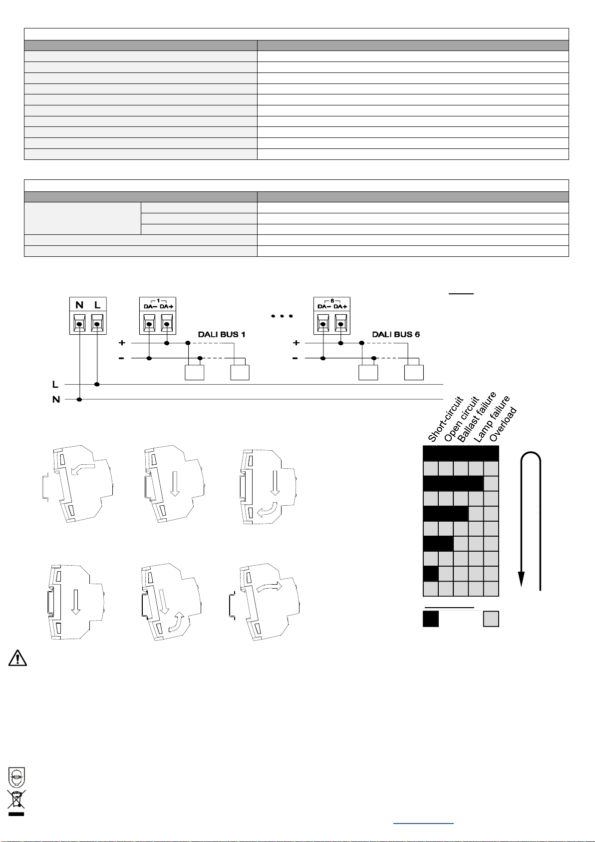
•Control of up to 20 DALI ballasts per channel in up to 4 channels only for logarithmic curve.
•Ballast replacement allowed with automatic detection.
•Error detection and monitoring (except multiaddress DALI ballasts).
•Burn-in, Stand-by and Auto-off functionality for each channel.
•Not suitable for emergency lighting control.
•Optional manual dimming control.
•External 110-230VAC 50/60Hz power supply.
•Total data saving on KNX bus failure.
•Integrated KNX BCU.
•Dimensiones 60 x 90 x 79mm (4,5 unidades DIN).
•DIN rail mounting (EN 50022), through pressure.
•DALI Standard compatible.
•Conformity with the CE directives (CE-mark on the right side).
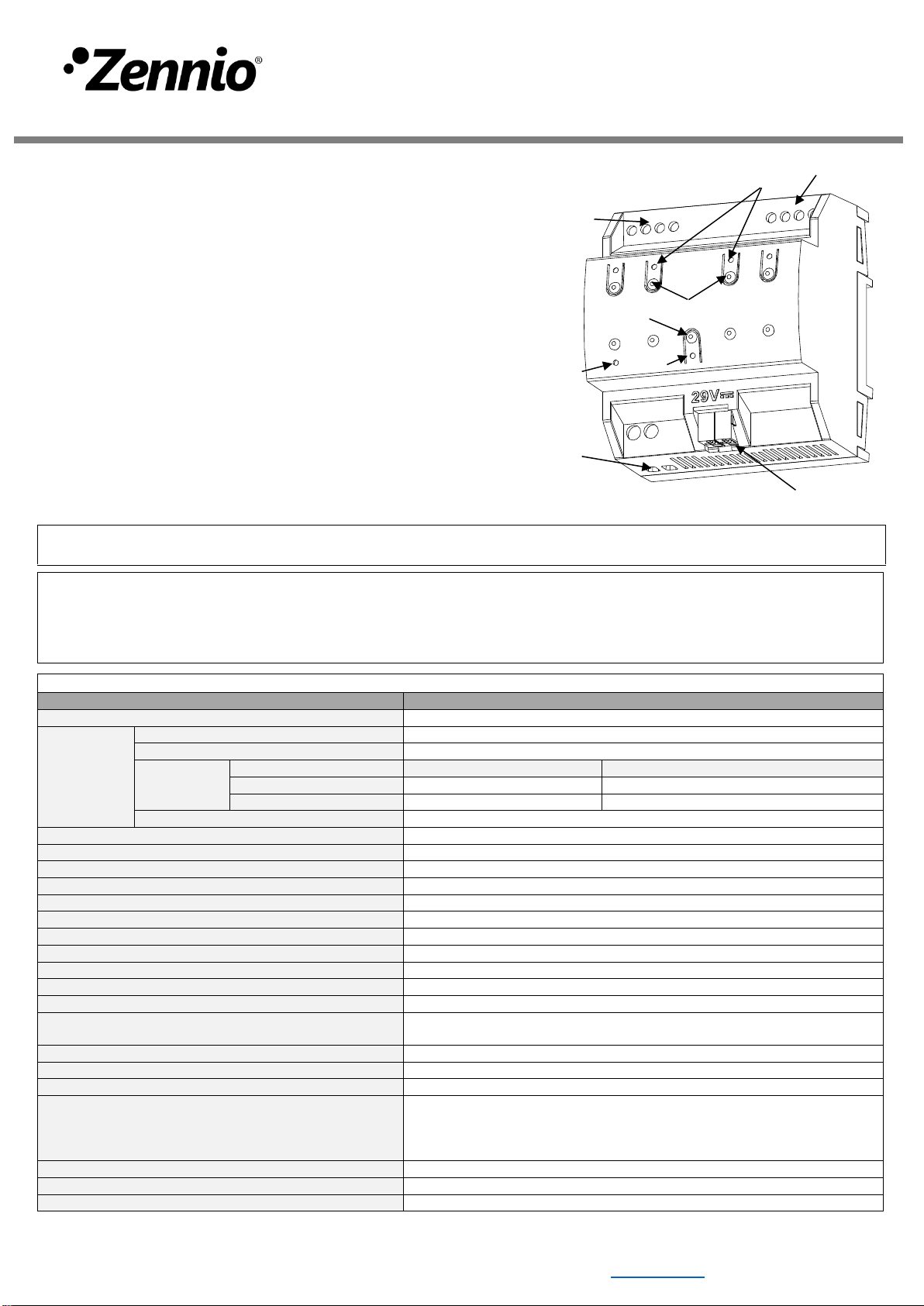
3. DALI channel control button
4. DALI channel status LED
5. Programming/Test button
Figure 1: DALIBOX Broadcast 4CH
Programming/test button: short press to set programming mode. If this button is held while plugging the device into the KNX bus, it enters the safe
mode. If this button is held for more than 3 seconds, the device enters the test mode.
Programming/Test LED: programming mode indicator (red). When the device enters the safe mode, it blinks (red) every half second. The manual mode
is indicated by the green color. During the start-up (reset or after KNX bus failure) and if the device is not in safe mode, it emits a red flash.
Electric operation control device
Typical TP1 bus connector for 0.80mm Ø rigid cable
Complementary characteristics
Independent device to be mounted inside electrical panels with DIN rail (EN
50022)
Response on KNX bus failure
Data saving according to parameterization
Response on KNX bus restart
Data recovery according to parameterization
The programming LED indicates programming mode (red) and test mode
(green). Each output LED indicates its status (fixed = active output; flashing
= error in the output). Power supply LED indicates the presence of supply
voltage.
¹ Maximum consumption in the worst case scenario (KNX Fan-In model)