manuals.online logo
Brands
  1. Home
  2. •
  3. Brands
  4. •
  5. Zennio
  6. •
  7. Recording Equipment
  8. •
  9. Zennio ZDID64V3 User manual

Zennio ZDID64V3 User manual

© Zennio Avance y Tecnología S.L. Edition 1 Further information www.zennio.com Page 1/2
DALI BOX Interface 64 v3
Interface for one DALI bus with up to 64 devices and 64 lighting groups
ZDID64V3 TECHNICAL DOCUMENTATION
FEATURES
•Possibility of controlling up to 64 DALI ballasts and up to 64 lighting
groups (groups from number 17 to number 64 are only for one DALI
ballast)
•Single Master DALI-2 Controller
•Compatibility with emergency lighting and color ballasts (DT8).
•Scene sending and saving
•Error detection and monitoring
•Burn-in, Stand-by and Auto-off functions
•Manual control through buttons and status indication through display
•1.54” display (128 x 64 pixels) for settings and notifications
•External power supply of 110-240 VAC 50/60 Hz
•Total data saving on KNX bus failure
•Integrated KNX BCU (TP1-256)
•Size 67 x 90 x 79 mm (4.5 DIN units)
•DIN rail mounting according to IEC 60715 TH35, with fixing clamp
•DALI Standard certified
•Conformity with the CE, UKCA, RCM directives (marks on the right
side)
1. DALI bus channel
2. Control buttons
3. Display
4. Programming button
5. Programming LED
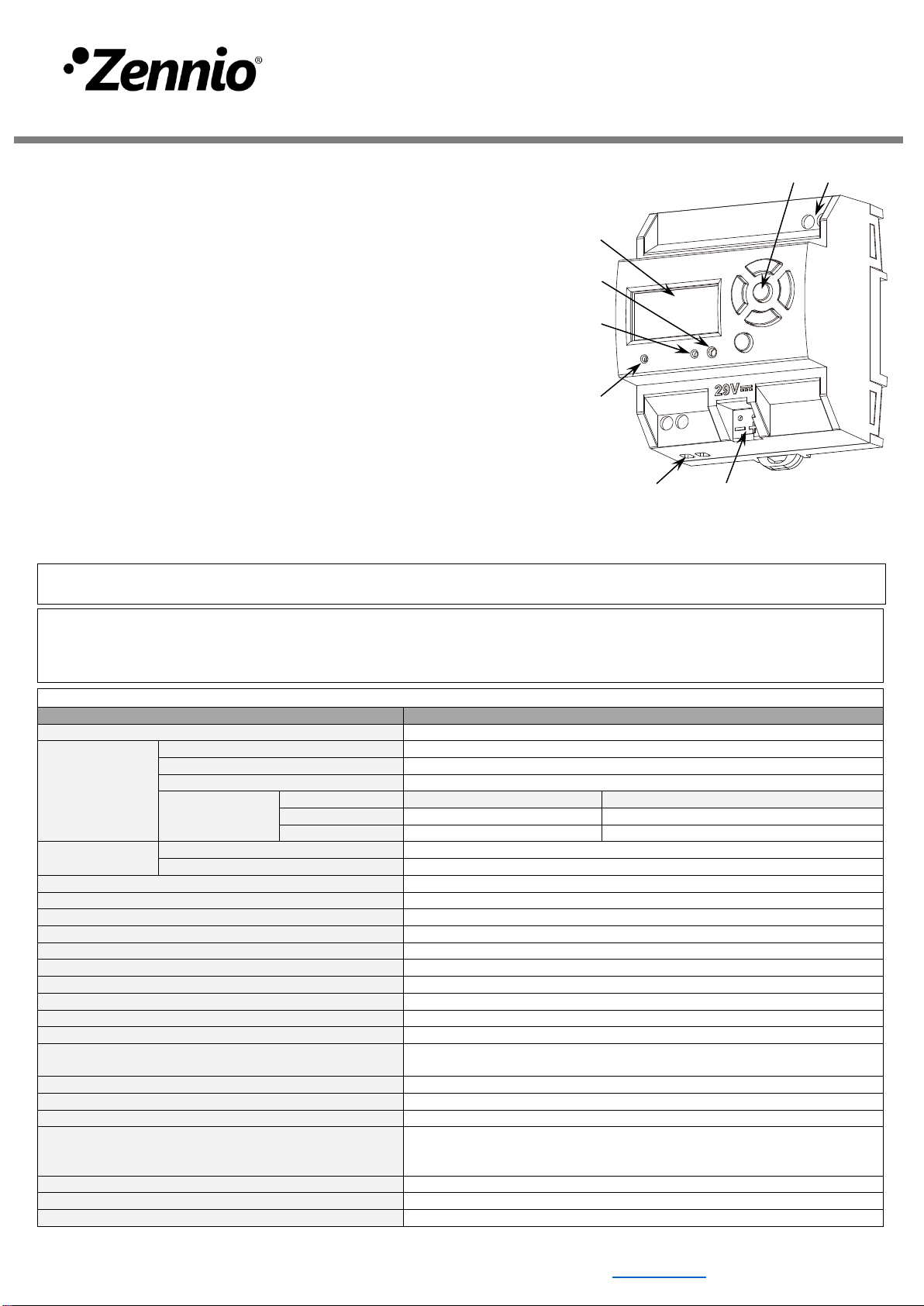
6. Power supply indicator LED
7. External power supply
8. KNX connector
Figure 1: DALI BOX Interface 64 v3
Programming button: short press to set programming mode. If this button is held while plugging the device into the KNX bus, it enters the safe mode.
Programming LED: programming mode indicator (red). When the device enters the safe mode, it blinks (red) every half second. During the start-up
(reset or after KNX bus failure) and if the device is not in safe mode, it emits a red flash.
GENERAL SPECIFICATIONS
CONCEPT
DESCRIPTION
Type of device
Electric operation control device
KNX supply
Voltage (typical)
29 VDC SELV
Voltage range
21-31 VDC
Connection type
Typical TP1 bus connector for 0.8 mm Ø rigid cable
Maximum
consumption
Voltage
mA
mW
29 VDC (typical)
6,2
179.8
24 VDC¹
10
240
External power
supply
Voltage
110-240 VAC 50/60 Hz PF=0.5
Maximum consumption
82 mA @ 110 VAC / 52 mA @ 230 VAC
Operation temperature
-5 .. +45 °C
Storage temperature
-20 .. +55 °C
Operation humidity
5 .. 95%
Storage humidity
5 .. 95%
Complementary characteristics
Class B
Protection class / Overvoltage category
II / III (4200 V)
Operation type
Continuous operation
Device action type
Type 1
Electrical stress period
Long
Degree of protection
IP20, clean environment
Installation
Independentdevice to be mounted inside electrical panelswith DIN rail (IEC
60715)
Minimum clearances
Not required
Response on KNX bus failure
Data saving according to parameterization
Response on KNX bus restart
Data recovery according to parameterization
Operation indicator
The programming LED indicates programming mode (red). The power
supply LED indicates external power (green). Display allows both
configuring the DALI system and supervising the current status.
Weight
195 g
PCB CTI index
175 V
Housing material
PC FR V0 halogen free
¹ Maximum consumption in the worst-case scenario (KNX Fan-In model).
1
3
2
7
5
4
6
8
© Zennio Avance y Tecnología S.L. Edition 1 Further information www.zennio.com Page 2/2
SAFETYINSTRUCTIONSAND ADDITIONAL NOTES
•Installation should only be performed by qualified professionals according to the laws and regulations applicable in each country.
•Do not connect the mains voltage nor any other external voltage to any point of the KNX bus; it would represent a risk for the entire
KNX system. The facility must have enough insulation between the mains (or auxiliary) voltage and the KNX bus or the wires of other
accessories, in case of being installed.
•The facility must be equipped with a device that ensures the omnipolar sectioning. Installation of a 10 A mini-circuit-breaker is
recommended. To prevent accidents, it must remain open in case of manipulation of the device.
•The device has a short-circuit protection fuse that, in case of activation, should only be rearmed or replaced by the Zennio technical
service.
•This device contains a security short-circuit proof transformer.
•Once the device is installed (in the panel or box), it must not be accessible from outside.
•For indoor use only.
•Keep the device away from water (condensation over the device included) and do not cover it with clothes, paper or any other material
while in use.
•The WEEE logo means that this device contains electronic parts and it must be properly disposed of by following the instructions at
https://www.zennio.com/en/legal/weee-regulation.
•This device contains software subject to specific licences. For details, please refer to https://zennio.com/licenses.
DALI OUTPUT SPECIFICATIONS AND CONNECTIONS
CONCEPT
DESCRIPTION
Number of channels
1
Output type / Voltage
DALI bus / 18 VDC SELV
Guaranteed current per channel
200 mA
Maximum current per channel
250 mA
Maximum DALI ballasts per channel
64
Maximum length of cable
300 m (@ 1.5 mm²)
Short-circuit protection
YES
Overload protection
YES
Over-voltage protection
YES
Connection method
Screw terminal block (0.5 Nm max.)
Cable cross-section
1.5-4 mm² (IEC) / 26-10 AWG (UL)
EXTERNAL POWER SUPPLY SPECIFICATIONS AND CONNECTIONS
CONCEPT
DESCRIPTION
Power supply protection
fuse
Voltage
250 V
Current
4 A
Response type
F (Fast acting)
Connection method
Screw terminal block (0.5 Nm max.)
Cable cross-section
1.5-4 mm² (IEC) / 26-10 AWG (UL)
WIRING DIAGRAMS
Figure 2: Mounting DALI BOX Interface 64 v3
on DIN rail
110-240 VAC
50/60 Hz
Ballast n
(n≤64)
Ballast 1
⚠In case of ballast replacement,
please follow the steps defined in
the user manual.
⚠In case of a DALI channel short
circuit, the device will monitor the
DALI channel in order to switch on
the output at full current just as the
short circuit is removed.
Attaching DALI BOX Interface 64 v3 to DIN rail:
Removing DALI BOX Interface 64 v3 from DIN rail:

Other Zennio Recording Equipment manuals

Zennio KLIC-DI SKY User manual

Zennio

Zennio KLIC-DI SKY User manual

Zennio ZRX-KCI4SO User manual

Zennio

Zennio ZRX-KCI4SO User manual

Zennio KNX ZRX-KCI4S0 Guide

Zennio

Zennio KNX ZRX-KCI4S0 Guide

Zennio KLIC-DI User manual

Zennio

Zennio KLIC-DI User manual

Zennio BIN 44 User manual

Zennio

Zennio BIN 44 User manual

Zennio KNX USB SC User manual

Zennio

Zennio KNX USB SC User manual

Zennio KNX KCI 4 S0 User manual

Zennio

Zennio KNX KCI 4 S0 User manual

Zennio ZRX-KCI4SO Guide

Zennio

Zennio ZRX-KCI4SO Guide

Zennio DALIBOX Interface 64/32 User manual

Zennio

Zennio DALIBOX Interface 64/32 User manual

Zennio DALIBOX ZDI-DLB4 Guide

Zennio

Zennio DALIBOX ZDI-DLB4 Guide

Zennio KLIC-DI Quick start guide

Zennio

Zennio KLIC-DI Quick start guide

Zennio DALIBOX ZDI-DLB4 Guide

Zennio

Zennio DALIBOX ZDI-DLB4 Guide

Zennio ZDI-DLI User manual

Zennio

Zennio ZDI-DLI User manual

Zennio KLIC-DD User manual

Zennio

Zennio KLIC-DD User manual

Zennio DALIBOX ZDI-DLB6 Guide

Zennio

Zennio DALIBOX ZDI-DLB6 Guide

Zennio DALIBOX ZDI-DLB4 Guide

Zennio

Zennio DALIBOX ZDI-DLB4 Guide

Zennio KIPI User manual

Zennio

Zennio KIPI User manual

Zennio KNX ZRX-KCI4S0 Guide

Zennio

Zennio KNX ZRX-KCI4S0 Guide

Popular Recording Equipment manuals by other brands

Mackie HDR 24 installation guide

Mackie

Mackie HDR 24 installation guide

urmet domus 1058/010 Installation and user manual

urmet domus

urmet domus 1058/010 Installation and user manual

Alesis MULTIMIX8 USB2.0 Reference manual

Alesis

Alesis MULTIMIX8 USB2.0 Reference manual

Advantech MIO-3150 Startup manual

Advantech

Advantech MIO-3150 Startup manual

Alesis TransActive user guide

Alesis

Alesis TransActive user guide

Nortel Succession 1000 Installation and configuration

Nortel

Nortel Succession 1000 Installation and configuration

Pneuance Audio Pneupod NP-1 Setup Instruction

Pneuance Audio

Pneuance Audio Pneupod NP-1 Setup Instruction

Vacron 16CH H.264 user manual

Vacron

Vacron 16CH H.264 user manual

Siemens DLC installation instructions

Siemens

Siemens DLC installation instructions

Juzisound Total SOLO Sampler 2 quick start guide

Juzisound

Juzisound Total SOLO Sampler 2 quick start guide

Signet DL50/K Installation and setup guide

Signet

Signet DL50/K Installation and setup guide

Sound Devices 788T User guide addendum

Sound Devices

Sound Devices 788T User guide addendum

Bailey 40 Series Instruction

Bailey

Bailey 40 Series Instruction

Hosa Technology TRACKLINK UXA-110 Connection and Setup Procedures

Hosa Technology

Hosa Technology TRACKLINK UXA-110 Connection and Setup Procedures

Next MX350 user manual

Next

Next MX350 user manual

Stereoping DELUXE DELAY manual

Stereoping

Stereoping DELUXE DELAY manual

MULTI MEASURING INSTRUMENTS MPR-601W instruction manual

MULTI MEASURING INSTRUMENTS

MULTI MEASURING INSTRUMENTS MPR-601W instruction manual

Siemens RNI installation instructions

Siemens

Siemens RNI installation instructions

manuals.online logo
manuals.online logoBrands
  • About & Mission
  • Contact us
  • Privacy Policy
  • Terms and Conditions

Copyright 2025 Manuals.Online. All Rights Reserved.