ZEP 212 CD User manual

Service ManualService Manual
For full warranty information, contact your delivering distribu-
tor or contact the manufacturer at info@warrantysvc.com
212 CD
p/n N84201

_________________
INSTALLATION DATE
______________________________________________________
MAKE/MODEL SERIAL NUMBER
______________________________________________________
SELLER
______________________________________________________
ADDRESS CITY/STATE/ZIP
______________________________________________________
NOTES:
SEM-00027B 20100303

1
Specifications
Specifications
1
English to Metric Conversions
1 gal/m = 3.7843 L/m
1 hp = .7457 kw
100 psi = 6.8964 bar
1 ft = .3048 m
1 in = 2.54 cm
1 lb = .4536 kg
(˚F – 32)
1.8 =˚C
Performance
Discharge Volume 2.0 gal/m / 7.5 L/m
Pump Head Pressure 1200 psi / 83 Bar
General
Minimum Inlet Water Pressure
over 65 psi may require water inlet regulator 10 psi / 0.69 Bar
Weight (Dry) 106 lbs / 48 kg
Spray Tips #4.0 (0˚,15°,25°,40°)
(#4.0 - 65˚) p/n JA0-650400-2B
(#4.0 - 15˚) p/n JA0-15040-2
Dimensions L – 29”, H – 23”, W – 22”
Trigger Gun & Wand Trigger
p/n C210a-00701
- Trigger Gun p/n J06-00121
- Trigger Wand p/n J06-00174
Hose Assembly
E212-00710
- Assembly, Hose 3/8” x 25’ P/N K02-03125E1
- Coupler P/N W04-31231-B
Chemical Low Pressure Metered
- Assembly, Hose p/n 4120-00904P
Water Pump Triplex, Oil Bath, Ceramic Plunger
p/n N07-00121
Electrical
Machine Voltage 115v 60Hz 1Ph
Current 18.4 AMP
Toggle Switch – SPST 15A p/n F04-00716
PUMP MOTOR
Motor Part Number F02-000138-UC
Motor Horsepower 2.3HP / 1.7 KW
Motor Speed 3450 RPM
Motor Voltage 115v / 230v 60 Hz 1PH
Motor Rating UL / ODP / C-Face


1
OPERATION TABLE OF CONTENTS
ELECTRIC DRIVEN COLD WATER CLEANER
TROUBLESHOOTING
•Machine 8
•Pump See Parts List Section
SERVICE
•Pump See Parts List Section
•Fuel Filter See Parts List Section
•Trigger Gun See Parts List Section
• Unloader See Parts List Section
• Machine Breakdown See Parts List Section
• Chemical Metering Valve See Parts List Section
COMPONENT ADJUSTMENT
Chemical Metering
•Flow Adjustment See Parts List Section
Unloader
•Pressure Adjustment See Parts List Section
WARRANTY Inside Back Cover
SPECIFICATIONS Inside Front Cover
SCHEMATIC Last Page
SAFETY INSTRUCTIONS
•Safety Symbols 3
•General 3
•Mechanical 4
•Electrical 4
INSTALLATION
•Electrical 5
•Extension Cord 5
•Water Supply 4
•Barrier 4
•Water Conditions 4
•Freezing 4
•Chemicals 4
OPERATION
•Pre Start-Up 5
•Start-Up 5
•To Clean, Apply Chemical, To Rinse 5
•Shut Down 6
MAINTENANCE
Machine
•Spray Tip Maintenance 7
•Belt Tension 7
•Schedule 7
•Flushing, Storage 7
Page Number Page Number
Supersedes 08-19-05 Z08-00481TC 05-18-06 Z08-00481TC

2
SAFETY, INSTALLATION, AND OPERATION
ELECTRIC DRIVEN COLD WATER CLEANER
1. Before operating this machine, read and observe
all safety, unpacking, and operating instructions.
Failure to comply with these instructions could
create a hazardous situation.
2. The operator of this equipment should not operate
this equipment when fatigued or under influence of
alcohol or drugs.
3. The operator of this equipment should be
thoroughly familiar with its operation and trained
in the job to be accomplished.
4. The operator of this equipment should wear
protective face shields and other protective
clothing as required for safe operation.
5. Keep all protective covers and shields in place.
Operating this machine with moving parts could
allow operator or bystander serious injury or even
death.
6. Do not operate the machine if any mechanicalfailure
is noted or suspected. Keep all shields in place.
7. Always point the gun assembly in a safe direction
and do not direct spray on the cleaner.
GENERAL SAEFTY
Supersedes 08-19-05 Z08-00481 05-18-06 Z08-00481
Read and understand this “OPERATOR’S
MANUAL” and “LABELS
ON THE MACHINE” before
starting.
MACHINE UNPACKING
ALL CLEANERS ARE CAREFULLY INSPECTED AND
CARTONED TO PROTECT AGAINST SHIPPING
DAMAGE. IF THERE IS DAMAGE OR MISSING PARTS,
THE TRANSPORTATION COMPANY AGENT SHOULD
MAKE A NOTATION TO THAT EFFECT ON THE BILL.
REFER TO THE PARTS LIST IN THIS MANUAL AND
ADVISE WHAT PARTS ARE MISSING OR DAMAGED.
IF AVAILABLE, GIVE THE INVOICE NUMBER ON ALL
ORDER BILLS. THIS PROCEDURE WILL ENABLE
NEEDED PARTS TO BE SHIPPED QUICKLY.
READ ALL Installation, Operation, and Maintenance
instructions before operating the machine.
NOTE: Refer to CLEANER MODEL for SERIAL NUMBER
location.
NOTE: Dimensions are in inches unless otherwise note.
The safety alert symbol. This symbol is used
to identify safety information about hazards that can
result in personal injury.
A signal word (DANGER, WARNING, or CAUTION) is used
with the alert symbol to indicate the likelihood and the
potential severity of injury. In addition, a hazard symbol
may be used to represent the type of hazard
DANGER indicates a hazard which, if not avoided,
will result in death or serious injury.
WARNING indicates a hazard which, if not avoided,
could result in death or serious injury.
CAUTION indicates a hazard which, if not avoided,
might result in minor or moderate injury.
CAUTION, when used without the alert symbol,
indicates a situation that could result in damage to
the equipment.
IMPORTANT SAFETY
INSTRUCTIONS
WARNING: RISK OF INJECTION OR
SEVERE INJURY. KEEP CLEAR OF
NOZZLE. DO NOT DIRECT DISCHARGE
STREAM AT PERSONS. THIS EQUIPMENT
IS TO BE USED ONLY BY TRAINED
OPERATORS.
AVERTISSEMENT:RISQUE D’INJECTION ET
DE BLESSURES GRAVES. SE TENIR À
L’ÉCART DU JET. NE PAS DIRIGER LE JET
DE SOTIE VERS D’AUTRES PERSONNES
CONFIER L’UTILISATION LE JET DE SOTIE
VERS D’AUTRES PERSONNES. CONFIER
L’UTILISATION DE CE MATÉRIEL À UN
OPÉRATEUR QUALIFIÉ.
ADVERTENCIA:RIESGO DE LA INYECCIÓN
O SEVERO LESIÓN. CLARO DE LA
SUBSISTENCIA DEL INYECTOR. NO DIRIJA
LA CORRIENTE DE LA DESCARGA EN LAS
PERSONAS. ESTO EL EQUIPO DEBE SER
UTILIZADO SOLAMENTE POR LOS
OPERADORESENTRENADOS.

3
5. All wiring and electrical connections should
comply with the National Electrical Code (NEC)
and with local codes and practices.
6. Fuses or circuit breakers should be compatible
with machine requirements. (See ELECTRICAL
section of MODELSPECIFICATIONS for power
requirements.)
7. High voltage may be present within this machine.
Servicing should only be performed by properly
trained personnel.
SAVE THESE SAFETY
INSTRUCTIONS
1. BARRIER: We recommend a barrier be installed
between the machine and wash area to prevent
moisture from coming in direct contact with
electrical controls, motors and transformers. This
will increase the machine’s life and lessen
electrical problems.
2. WATER SUPPLY: This machine must have a water
supply meeting or exceeding the maximum
discharge volume specified in the PERFORMANCE
section, and a minimum water inlet pressure
specified in the GENERAL section of the MODEL
SPECIFICATIONS.
3. WATER CONDITIONS: Local water conditions affect
the coil adversely more than any other element. In
areas where troublesome conditions may exist with
like equipment (such as water heaters), we
recommend the use of a water softener.
4. FREEZING: This machine must be protected from
freezing according to STORAGE section of MACHINE
MAINTENANCE.
5. CHEMICALS: Mix chemicals per the chemical
manufacturers printed directions. Follow all mixing,
handling, application, and disposal instructions.
Wear gloves, boots, goggles, and protective clothing
appropriate for the chemical being used.
INSTALLATION
Supersedes 08-19-05 Z08-00481A 05-18-06 Z08-00481A
8. Do not leave this machine unattended when it is
operating
9. All installations must conform to all applicable
Local codes. Contact your electrician, plumber,
utility company or seller for details.
10. If a water leak is found, DO NOT OPERATE THE
MACHINE. Shut off the motor and repair.
11. Follow instructions on how to stop the machine
and bleed pressures quickly. Be thoroughly
familiar with the controls.
12. When starting a job, survey the area for possible
hazards and correct before proceeding.
13. If chemicals are used in conjunction with this
equipment, read and follow the product label
directions.
14. Do not start the machine unless the gun assembly is
firmly gripped by the machine operator. Failure to do
this could result in injury from flying hose and gun
assembly.
1. All guards, shields, and covers must
be replaced after adjustments are
made to prevent accidental contact
with hazardous parts.
2. Drive belts must be inspected and tightened
periodically to operate at optimum levels.
3. Inspect machine for damaged or worn
components and repair or replace to avoid potential
hazards. Do not operate the machine if any
mechanical failure is noted or suspected.
4. Always use the correct size spray tip specified in
the GENERAL section of the MODEL
SPECIFICATIONS or MODEL EXPLODED VIEW.
5. Do not start the machine until you have observed
all safety instructions and operating found in the
operating manual.
1. This machine must be electrically grounded.
Failure to have the machine grounded may
result in the operator being electrically
shocked and even death.
2. Do not plug–in or un–plug machine with wet
hands.
3. Keep power cords and connections (connectors)
out of water.
4. If an extension cord must be used to operate this
machine, it should be as short as possible. The
extension cord must be properly sized and fitted
with a grounding type plug and receptacle.
MECHANICAL SAFETY
ELECTRICAL SAFETY

4
Supersedes 08-19-05 Z08-00481B 05-18-06 Z08-00481B
ELECTRICAL INSTALLATION
PRE START-UP
OPERATING
INSTRUCTIONS
WARNING: ELECTRICAL SHOCK HAZARD
AVERTISSEMENT: LE DANGER ELECTRIQUE DE CHOC
ADVERTENCIA: CHOQUE ELÉCTRICO PELIGRO
1. The first time the machine is operated, after
repairs have been made, or if the machine has set
for a period of time (30 days or more) follow the
following procedures.
A. Check the tension of the belt (if so equipped)
per instructions in MACHINE MAINTENANCE.
B. Flush the machine per instructions in
MACHINE MAINTENANCE.
C. Install float tank drain plug (if so equipped).
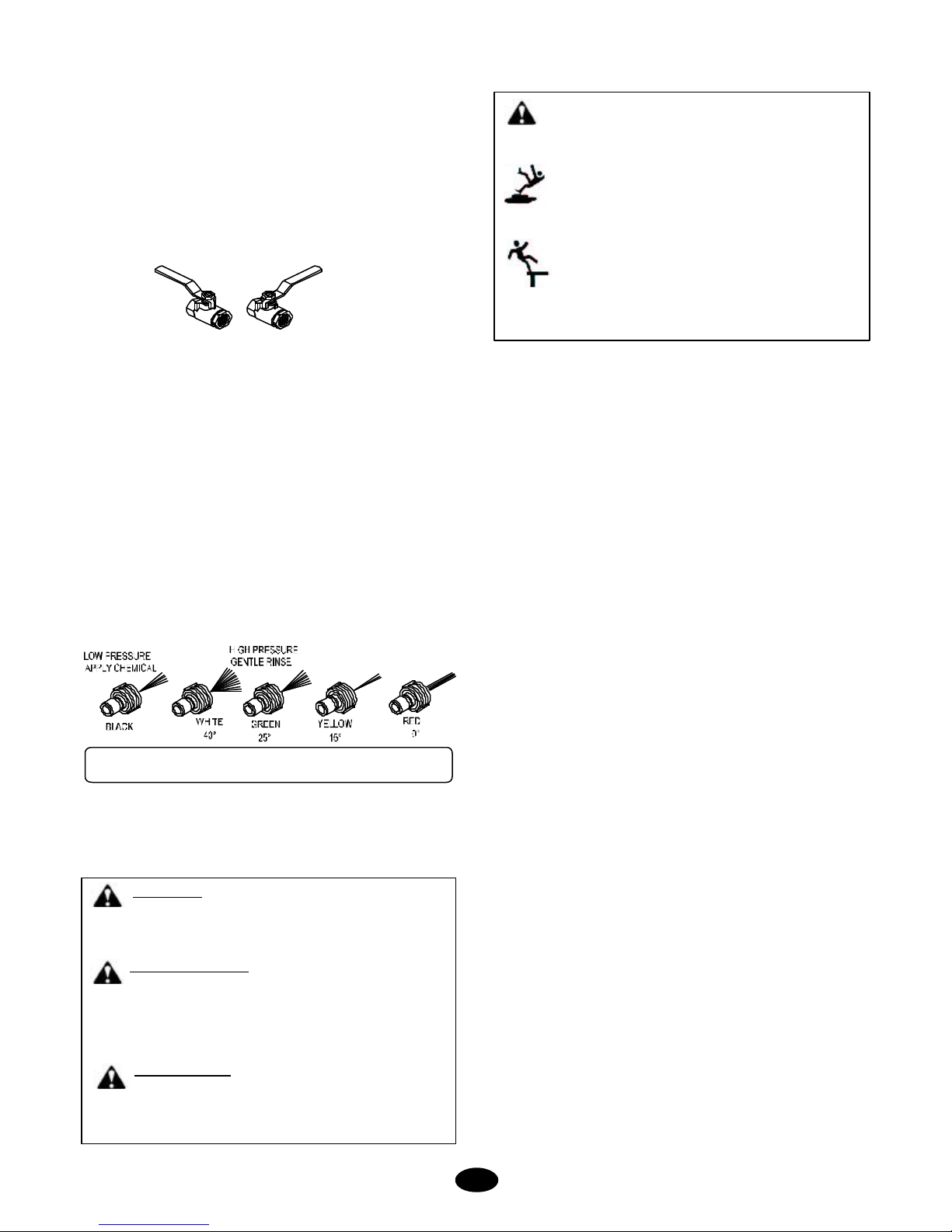
D. Open float tank ball valve (if so equipped).
CAUTION: Always use the factory supplied wash
hose with your machine. Do not substitute other
hoses as a potential safety problem may develop.
CAUTION: If machine has been exposed
to sub-freezing temperatures, it must be
thoroughly warmed to above freezing before
operating. Failure to warm machine can cause
damage to the pump packings and other
components.
2. Read and observe all items in “CLEANER
INSTALLATION”.
♦ Refer to the MAINTENANCE SCHEDULEfor any
maintenance to be performed before operation.
♦ELECTRICAL: Connect the machine to an
electrically grounded circuit that is fuse or circuit
breaker protected. Do not use any type of adapter.
If the correct type of receptacle is not available,
have one installed by a qualified electrician.
♦OIL LEVEL: Check the oil level in the water pump.
♦BELT: Make sure belt tension and condition is as
specified in MACHINE MAINTENANCE.
♦METERING VALVE ( if so equipped): Make sure
the metering valve is closed before operation. If air
enters the system through this valve, poor
performanceandmachinedamagewilloccur. Refer
to the metering valve insert for proper operation.
♦WATER SUPPLY: This machine must have a water
supply meeting or exceeding the maximum
discharge volume specified in the PERFORMANCE
section, and a minimum water inlet pressure of 40
PSI /12.1KGM.
♦LIME: Water containing large amounts of lime,
calcium or other similar materials can produce a
coating on the inside of the spray tip, impact nozzle
and coil pipe.
1. ELECTRICAL: Connect the machine to an
electrically grounded circuit that is fused or circuit
breaker protected. The circuit must match that
specified in the ELECTRICAL section under
MODEL SPECIFICATIONS.
WARNING: To reduce risk of electrocution, keep all
connections dry and off the ground. Do not
touch plug with wet hands.
CHART FIGURES ARE BASED ON NOT MORE THAN
100 FOOT
(Based on Ambient Temperature of 86°F (30°C)).
*Use Amp Draw indicated the same or higher than your
machine output.
EXAMPLE: Machine Amp Draw 51, use 55 (2 Conductor).
The thermostat type of cord shall be C, PD, E, EO, EN, S,
SO, SRD, SJ, SJO, SV, SVO, SP.
The thermo set plastic types shall be ET, ETT, ETLB, ETP,
ST, STO, SRDT, SJT, SJTO, SVT, SVTO, and SPT.
2. EXTENSION CORD: The use of an extension cord
that has undersize wire compared to the amp draw of
your machine will adversely limit the starting load
carrying abilities of the motor and machines
performance. Use only 3-wire extension cords that
have 3-prong plugs and 3-pole cord connectors that
accept the plug from the product. Use only
extension cords that are intended for outdoor use.
These extension cords are identified by a marking
“Acceptable for use with outdoor appliances; store
indoors while not in use.” Use only extension cords
having an electrical rating not less than the rating of
the product. Do not use damaged extension cords.
Use an extension cord in good repair free of frays or
cracks in the outer covering. Do not abuse
extension cord and do not yank on any cord to
disconnect. Keep cord away from heat and sharp
edges. Always disconnect the extension cord from
the receptacle before disconnecting the product from
the extension cord.

5
Supersedes 08-19-05 Z08-00481C 05-18-06 Z08-00481C
♦FLOAT TANK: Check the float tank (if so equipped)
to assure it is full and the float valve shuts off securely.
♦BALL VALVE: Check the position of the ball valve on
the outlet side of the float tank (if so equipped) that
it is in the open position.
♦SPRAY TIP:Choose the correct spray tip for the job
to be performed.
Quick-Connect spray tipshave fixed spray patterns that
are more consistent than those produced by an adjust-
able nozzle. Each tip is color-coded for easy
identification.
White (40°): produces a wide-fan spray for general
cleaning and rinsing.
Green (25°): provides a narrower-fan spray for tough
stains in cleaning applications.
Yellow (15°): maintains a tight-fan spray with intense
cleaning power for heavy-duty cleaning and paint
preparation.
Red (0°): creates a concentrated pinpoint water jet for
stubborn stains on concrete, masonry, or steel, and for
stripping paint.
1. With the gun assembly in hand (on trigger gun models
hold the trigger gun valve in open position) and with
a good flow of water turn the switch to the “pump”
position.
CAUTION: A good flow of water must be flowing
from the end of a gun for 30 seconds, before
proceeding. Lack of water can cause damage to
the water pump and like components.
CAUTION: On a machine equipped with a trigger
gun valve, if the trigger gun valve remains in the closed
position for more than 3 minutes, water pump damage
may occur.
CAUTION: Do not operate with the trigger gun valve
closed for more than 3 minutes or water pump damage
may occur.
2. TO CLEAN:
A. Start on the lower portion of the area to be cleaned
andworkupusinglong,even,overlappingstrokes.
B. Dirt is generally removed easily if grease and/or
oil are not present. However if grease and/or oil
are present, hot water and chemical will
accelerate in the cleaning process.
3. TO APPLY CHEMICAL:
CHEMICAL: Use factory recommended chemicals
for best cleaning action and for extended pump life.
Contact your dealer for chemicals available. Follow
instructions on chemical container.
Note : If the valve is open without the chemical line
in a source the water pump will draw air causing
the system not to pressure up.
Mix chemicals per label instructions. Use necessary
safety percautions.
When chemical is desired, the system must be
switched over to the low pressure nozzle to draw
chemical.
A. Insert chemical screen into chemical container.
B. Adjust metering valve or injector. Install your
injector tip.
C. If the gun assembly is equipped with variable or
multiple nozzle assembly, adjust to low
pressure, multiple nozzle assembly, adjust as
desired.
OPEN CLOSED
BALL VALVE POSITION
START-UP
WARNING: RISK OF INJECTION OR SEVERE INJURY.
KEEPCLEAR OF NOZZLE.DO NOTDIRECTDISCHARGE
STREAM AT PERSONS. THIS EQUIPMENT IS TO BE
USED ONLY BY TRAINED OPERATORS.
AVERTISSEMENT:RISQUE D’INJECTION ET DE
BLESSURES GRAVES. SE TENIR À L’ÉCART DU JET.
NE PAS DIRIGER LE JET DE SOTIE VERS D’AUTRES
PERSONNES CONFIER L’UTILISATION LE JET DE SOTIE VERS
D’AUTRES PERSONNES. CONFIER L’UTILISATION DE CE
MATÉRIEL À UN OPÉRATEUR QUALIFIÉ.
ADVERTENCIA:RIESGODELAINYECCIÓNOSEVERO
LESIÓN. CLARO DE LA SUBSISTENCIA DEL INYECTOR.
NO DIRIJA LA CORRIENTE DE LA DESCARGA EN LAS
PERSONAS. ESTO EL EQUIPO DEBE SER UTILIZADO
SOLAMENTE LOS OPERADORESENTRENADOS.
WARNING: Use of pressure washer can create puddles
and slippery surfaces.
High pressure spray could cause you to fall if you are too close
to the cleaning surface.
• Keepspray nozzlebetween 8to24 inchesaway from
cleaning surface.
• Operate this unit on a stable surface.
• The cleaning area should have adequate slopes and
drainage to reduce the possibility of a fall due to slippery
surfaces.
• Be extremely careful if you must use the pressure
washerfrom aladder,scaffolding oranyother relatively
unstable location.
• Firmly grasp spray gun with both hands when using high
pressure spray to avoid injury when gun kicks back.

6
UPSTREAM CHEMICAL INJECTION:
When injecting chemicals “upstream” what you are doing
is introducing chemicals to the water flow as it enters the
actual pump inlet and requires a float tank. The popularity
of this type of chemical injection is due to the fact that this
allows chemicals to be applied at full pressure
a major advantage for productivity.
DOWNSTREAM CHEMICAL INJECTION:
Mounted to the outlet of the pump or the coil a
downstream injector introduces chemicals to the water flow
AFTER it leaves the pump or the coil. This effectively
eliminates the major risks of exposing the inner workings
of a pump to harsh chemicals. When chemical is
desired, the system must be switched over to the low
pressure nozzle to draw chemical.
A. Engage the trigger safety latch on the spray
wand. Pull back the Quick-Connect collar on
the end of the wand and remove the tip. Now
insert “black” tip into the fitting, and release
the collar. You can draw chemical only with the
“black” low pressure nozzle.Tug on spray tip to
make sure the connection is secure. Rotate to
desired spray angle. For most effective
cleaning, keep spray tip from 8 to 24 inches
away from the cleaningsurface.
B. Insert chemical screen into chemical container.
C. Turn the burner switch to the “off” postion.
There will be air in the chemical line. Air heats
very quickly and needs to be eliminated
before the burner can be turned on.Open the
metering valve counter clockwise with the
trigger gun open allowing the chemical to
come up the chemical line. Chemical should
begin moving up the chemical line. Once t he
chemical line is completely full, trigger the gun
on and off numerous times to break any
possible air locks. Turn burner system switch to
“on” position.
D. If the gun assembly is equipped with variable or
multiple nozzle assembly, adjust to low
pressure.
E. If the gun assembly is equipped with a dual
lance wand open the valve.
Do not allow the detergent to dry on the surface
(prevents streaking).
TO RINSE:
A. If the machine is equipped with a panel mounted
metering valve, close the chemical metering valve
(if so equipped). NOTE: It is advisable to dip the
chemical screen in a container of clean water and
open the valve 1 minute to clean the valve of any
remaining residue.
B. If the gun assembly is equipped with variable or
multiple nozzle assembly, open and close to clean
nozzle of any remaining residue.
C. After a clear flow of water is noted from the end
of the wand, start from the top, working downward
using long, overlapping strokes.
1. Turn the switch to the pump off position.
2. Turn off the water supply.
3. If freezing conditions may exist, refer to STORAGE in
MACHINE MAINTENANCE.
CAUTION: You cannot draw an abrasive product such
as an aluminum brightner. It will cause an non-
warrantable premature pump failure.
SHUT-DOWN

7
MACHINE
MAINTENANCE
Electric Driven Cold Water Cleaners
BELT TENSION
STORAGE
SPAN
DEFLECTION
SPAN
SPRAY TIP MAINTENANCE
FLUSHING
x
05-12-06 Z08-02783 05-12-06 Z08-02783
6. Remove spray tip from gun assembly.
7. With the gun assembly in hand (on trigger gun models
hold the trigger gun valve in open position) and with a
good flow of water turn switch to the PUMP position
CAUTION: DO NOT RUN PUMP WITHOUT WATER,
AS THIS WILL CAUSE DAMAGE TO THE PUMP AND
VOID WARRANTY.
8. When clean water flows from the gun, turn switch to
the “OFF” position. Reinstall spray tip.
10. With the gun assembly in hand turn on the switch. On
trigger gun models hold the trigger gun valve in open
position.)
11. When clean water flows from gun, turn switch off the
PUMP position
11. If freezing conditions may exist, refer to “STORAGE”
section.
13. Turn off and disconnect the water supply. Disconnect
elctrical supply.
1. Rinse the chemical line by inserting the screen into a
container of clear water and open the metering valve 1
minute to clean it of any remaining residue. Be sure
the chemical metering valve is closed when finished.
2. Disconnect the water supply. Remove the spray tip
nozzle from gun assembly and wire to machine.
3. Check the position of the ball valve (if so equipped) on
the outlet of the float tank assuring it is in the closed
position.
4. Attach an air chuck to the air valve stem on the pump
assembly. With the trigger gun in the open position,
apply air until a mixture of air and very little water is
coming from the gun wand . Allow air to blow for 60
seconds. Turn switch to the “OFF” position. Remove
the air chuck.
5. Fill a 1-gallon container with Ethylene Glycol type
antifreeze. Minimumshouldbeamixtureof½ antifreeze
and ½ water strength before each use, as the antifreeze
will dilute with use.
6. Install a 2-ft garden hose to the water inlet. Insert the
other end into a container of antifreeze solution.
7. With the gun assembly in hand turn on the switch. On
trigger gun models hold the trigger gun valve in open
position.)
8. Turn off the switch just prior to running out of antifreeze
mixture.
9. Disconnect electrical supply, and the gun and hose.
10. Place machine in a dry place protected from weather
conditions.
1. Correct belt tension will allow a 1/64- inch deflection
for each inch of span between pulley centers with a
6-pound force applied in the middle of the span.
EXAMPLE: A 6-pound force applied at the middle of
an 8 inch span should produce a deflection of 8/64
inch or 1/8 inch.
2. Belts can be tightened or loosened by loosening the
nuts holding the pump assembly to the motor mount.
Then tighten or loosen the j-bolt on the motor mount.
Retighten the pump assembly after the desired
tension is reached.
1. Remove the spray tip from the gun assembly.
2. Blow out debris with compressed air from the outside
in. Any debris remaining in the inlet side of the nozzle
should be cleaned out. If lime or chemical scale is
present in the inlet side, the nozzle may be soaked
in descaling solution or replaced. If the tip is worn,
replace with one specified in the GENERAL section
of MODEL SPECIFICATIONS or MODEL
EXPLODED VIEW.
3. Before replacing spray tip flush the machine per
“FLUSHING”.
4. Reinstall Spray tip to gun assembly.
1. Connect machine to an electrically grounded circuit
that is fuse or circuit breaker protected.
2. Connect machine to a pressurized water supply
meeting the requirements specified in the GENERAL
section of the MODEL SPECIFICATIONS.
3. Turn on the water supply.
4. Check the float tank (if so equipped) to assure it is
full and the float valve shuts off securely.
5. Check the position of the ball valve (if so equipped)
on outlet line of the float tank assuring it is in the
open position.

8
MACHINE MAINTENANCE SCHEDULE
EACH HR AFTER FIRST EVERY EVERY EVERY
DAILY 8 HRS 50 HRS 50HRS 100 HRS 500 HRS YEARLY
ELECTRIC DRIVEN OIL FIRED
CLEANERS
OIL BATH WATER PUMP:
Oil Level- check and add as needed per PUMP
SERVICE insert.
Oil Change- drain and refill per PUMP SERVICE
insert. CAUTION: Used oil must be disposed into
an enviromental safe container and brought to an oil
recycling center.
Oil contamination- Milky color indicates water.
HOSES:
Blistering, Loose Covering
Abrasion of cover exposing reinforcement.
Cuts exposing reinforcement.
BELTS:
Cracks or fraying
Belt Tension- For correct tension, see MACHINE
MAINTENANCE insert.
LEAKS:
Check for water and buildup of scale at pipe
connections.
SCREEN-WATER:
Check Inlet Hose Screenfor debris.
Check float Tank Hose Screen ( if so equipped)
for debris.
Check Water Filter (if so equipped) for debris see
breakdown elsewhere in this manual.
SPRAYTIP:
Check tip for debris.
GUARDS AND SHIELDS:
Check that all guards and sheilds are in place and
secure.
PUMP MOTOR WITH GREASE FITTINGS:
Remove drain plug. Use 1 or 2 full strokes of shell
“DOBLIUM RB”, Cheveron”SR1 No.2” or Texaco
“PREMIUM RB”. Operate for 20 minutes and replace
drain plug.
FREEZING TEMPERATURES:
Freezing temperatures break coils and water
pumps. See STORAGE in the MACHINE MAINTE-
NANCE section for cold weather instructions.
Supersedes 11-23-03 Z08-02767 05-12-06 Z08-02767

98
ELECTRICMOTOR DRIVENCOLDWATERCLEANERS
1. Poorcleaning
action.
2. Machine will not
draw chemical.
3. Lowoperating
pressure.
4. Excessive,
unusual noise.
5.Beltsslipping.
A. Hard water.
B.Low pressure.
C.Little or no chemicalbeingdrawn.
D.Improper chemical.
E.Improperchemicalmixture.
F. Lowdischargepressure.
A. Nochemicalsolution.
B. Metering valve not open.
C.Chemicallinestrainerclogged.
D. Airleak in Chemical line.
E. Metering valve clogged.
F.Restrictororificetoolargeormissing.
A. Insufficeint water supply.
B. Incomingwater hose too small.
C. Watersupply hose toolong.
D. Beltslippage.
E. Worn belt.
F. Spray tip worn or wrong size.
G. Dirty or worn check valves in water
pump.
H.Watersupplyhosekinked.
I. Inlet filter screen clogged.
J. Motor runs slow.
K. Airleak in inletplumbing.
L. Defective water pump.
M.Leaking discharge hose.
N.Chemicalmeteringvalveopenand
sucking air.
O. Defective unloader.
P. Inlet ball valve not fully open (if so
equipped).
A. Pump.
B. Defective motor.
C. Pulleysrubbing.
D. Misalignmentofpump&motor
A. Beltstoo losse.
B. Excessivebackpressure.
C. Defective water pump.
A. Connect the machine to a water softner.
B.See“Lowoperatingpressure.”
C.See“machinewillnotdrawchemical.”
D.Obtain proper chemical.
E. Mix chemical per the label. Follow all the mixing,
handling,application,anddisposalinstructions.
F.See“Lowoperatingpressure.”
A.Replenish supply.
B. Turn metering valve knob to open.
C.Removescreenandcleaan.
D.Tightenallfittingsandhosesforthechemicalline.
E.Disassembleandclean.
F. Installpropersizeorifice.
A.The water supply mustmeetorexceedthemaximum
discharge volume specified in the PERFORMANCE
sectionof the MODEL SPECIFICATIONS section , and
minimumwater inlet pressure of10PSI/0.68 BAR.
B.Uselargerwatersupplyhose.
C.Useshorterwatersupplyhose.
D. Tighten belt per instructions inMACHINE
MAINTENANCE insert.
E. Replace bely per CLEANER EXPLODED VIEW.
F. Replacewithspray tip specified in theGENERAL
section of MODEL SPECIFICATIONS.
G. See PUMP TROUBLE SHOOTING.
H.Straighten hose.
I. Cleanwaterfilterscreenorhoseinletscreen.
J. See“Pumpmotorstartssloworoverheatsand
stops.”
K. Tightenall fittings.
L . See PUMP TROUBLESHOOTING.
M. If a water leak is found, DO NOT OPERATE THE
MACHINE. Disconnect the power andreplace hose.
N.Resupplychemical,placesoapscreeninwater,or
shut off metering valve.
O.Repairorreplaceunloadervalve.
P. Open inlet ball valve completely. (Handle parallel w/
valve boody).
A. See PUMP TROUBLESHOOTING.
B.CallservicetechnicianortakeenginetoReapir/
Warranty station.
C. Adjustshieldsorpulley(s).
D. Realignpumpandengine.
A. Tighten per instruction on MACHINE MAINTENANCE.
B. See“ExcessiveBackPressure.”
C. See PUMP SERVICE.
REMEDY
CLEANERTROUBLESHOOTING
POSSIBLE CAUSE
TROUBLE
Supersedes01-16-04 Z08-02784 01-17-07 Z08-02784

10
Supersedes01-16-04 Z08-02784A 01-17-07 Z08-02784A
CLEANERTROUBLESHOOTING(CONT.)
ELECTRICMOTOR DRIVENCOLDWATERCLEANERS
TROUBLE POSSIBLE CAUSE REMEDY
A. Spray tip built up with lime.
B. Water pump turning too fast.
C. Releif valve defective.
A. Defective belt.
B. Defective Pump.
C.Defective accumulator.
A. No power.
B. Defective motor starter or
ON/OFF switch.
C. Defective motor.
A. Pump frozen
B. Defective Motor.
C.Defective water pump
D.Excessive back pressure.
A. Low voltage.
B.Excessivebackpressure.
C. Defective motor.
A. Motor starter “kicked out” (if so
equipped) or thermal overload
tripped.
B.Excessivebackpressure.
C. Defective motor.
A. Incoming voltage incorrect.
B.Notlargeenoughextensioncord.
C.Toolongextensioncord.
A.Machine improperly grounded.
B. Outlet not grounded.
C. “Adapter” used.
D. Defective extension cord.
A. Remove and clean, or replace spray tip with tip
specified in GENERAL section of MODEL
SPECIFCATIONS.
B. See MODEL SPECIFICATIONS.
C.Remove and replace.
A. Removeandreplaceusingbeltspecifiedin
CLEANER EXPLODED VIEW or the GENERAL
section of MODEL SPECIFICATIONS.
B. See PUMP TROUBLESHOOTING.
C. Recharge/replace.
A. Useadifferent outlet, check fuses inmain
disconnect switch. Replace fuse if blown.
B. Callservice technician.
C.Callservicetechnichian,ortakemotortorepair/
Warranty station.
A.Machinemustbe thoroughly warmed to above
freezing.
B.CallservicetechnicanortakemotortoRepair/
Warranty station.
C. See PUMP SERVICE.
D.See“ExcessiveBackPressure.”
A. See “Low voltage.”
B. See“ExcessiveBackPressure.”
C. Callservicetechnichian, or take motor toRepair/
Warranty station.
A. Turn motor starter off to reset, then turn on, or push
thermal overload reset button on motor.
B. See“ExcessiveBackPressure.”
C. Callservicetechnichian, or take motor toRepair/
Warranty station.
A. Haveaqualifiedtechniciancheckmotorterminal
voltage. Correct voltage is inMODEL
SPECIFICATIONS.
B.Useanextensioncordwithamperesorwattsrating
as high or higher than that of theMODEL
SPECIFICATIONS.
C.Shorten extension cord.
A. STOP! Operating machine. call service
technichian.
B. Haveproperly wired outlet installed.
C. Discard“Adapter” andusegroundedoutlet.
D. Replaceextension cordwithgroundedtype
connectorsandamperesor watts rating as high or
higher in MODEL SPECIFICATIONS.
6. Excessive back
pressure.
7. Excessive vibration.
8. Pumpmotorwillnot
start (motor does not
hum).
9. Pumpmotorwillnot
start (motor hums).
10. Pumpmotor starts
slow or overheats
and stops.
11. Pumpmotor stops
and will not start.
12. Low voltage.
13.Machine shocks
operator.

2Final Assembly
Final Assembly
SERIAL NUMBER
ASSEMBLY, FINAL
p/n: E212-20420
3/9/2009
ITEM
NO. PART NUMBER PART DESCRIPTION QTY.
1 4120-00902P ASSEMBLY, CHEMICAL LINE 1
2 C210A-00701 ASSEMBLY, GUN 1
3 E212-00603 ASSEMBLY, CLEANER 1
4 E212-00710 ASS'Y, HOSE - 3/8 X 25 5000
PSI 1
5 F04-00451 GROMMET, RUBBER 5
6 J00-15040-2 TIP, SPRAY - #1504 1
7 JA0-65400-2B TIP, SPRAY 1
8 W02-00033 CLAMP, HOSE 1
9 Z01-00018 HANDLE, GRIP 2
1
3
4
2
55 7
3
6
8
9

3
Trigger Gun & Wand
Trigger Gun & Wand
2
1
3
3/25/2009
p/n: C210A-00701
ASSEMBLY, GUN
ITEM
NO. PART NUMBER PART DESCRIPTION QTY.
1 J06-00121 GUN, TRIGGER RL24 1
2 J06-00174 WAND, GUN - 24" 1
3 W04-24221-2 COUPLER, SOCKET 1
E212-00710 PART LIST
ITEM PART NUMBER PART DESCRIPTION
1 W04-31231-B Coupler, 3/8M X 3/8FNPT
2 K02-03125-1 Assembly, Hose – 3/8 X 25’

4Trigger Gun & Wand
3/3/2010
p/n: E212-00603
ASSEMBLY, CLEANER
ITEM
NO. PART NUMBER PART DESCRIPTION QTY.
1 435G-00130 FRAME, MOUNTING 1
2 AR58-02003 ROD, CRS - 5/8" X 20 1/4" 1
3 E212-00501 ASSEMBLY, PUMP 1
4 F02-00093-P COVER, PLATE W/HOLE -
MOTOR 1
5 F02-00138-UC MOTOR, ELEC - 2.3HP 1
6 F04-00179 CORDSET - GFI 115V X 15' 1
7 F04-00310 CONNECTOR, CONDUIT 1
8 F04-00716 SWITCH, TOGGLE - 115V -
15AMP 1
9 F04-00716-1 PLATE, TOGGLE SWITCH 1
10 G02-00018A ASS'Y, TIRE & RIM - 10" 2
11 H04-31306 SCREW, CAP - 5/16 X 3/4 6
12 H04-37509 SCREW, CAP 4
13 H05-31303 WASHER 4
14 H05-37500 WASHER, FLAT - 3/8 6
15 H06-31300 NUT, LOCK - 5/16" 6
16 H06-62500 NUT, PAL 2
17 H10-31302 MOUNT,RUBBER-WASHER
5/16 DIA. HOLE 2
18 Z01-00124 TOGGLE, SWITCH BOOT 1
12
1
3
510
5
4
18
8
7
6
13

5
General Assembly
General Assembly
3/3/2010
p/n: E212-00603
ASSEMBLY, CLEANER
ITEM
NO. PART NUMBER PART DESCRIPTION QTY.
1 435G-00130 FRAME, MOUNTING 1
2 AR58-02003 ROD, CRS - 5/8" X 20 1/4" 1
3 E212-00501 ASSEMBLY, PUMP 1
4 F02-00093-P COVER, PLATE W/HOLE -
MOTOR 1
5 F02-00138-UC MOTOR, ELEC - 2.3HP 1
6 F04-00179 CORDSET - GFI 115V X 15' 1
7 F04-00310 CONNECTOR, CONDUIT 1
8 F04-00716 SWITCH, TOGGLE - 115V -
15AMP 1
9 F04-00716-1 PLATE, TOGGLE SWITCH 1
10 G02-00018A ASS'Y, TIRE & RIM - 10" 2
11 H04-31306 SCREW, CAP - 5/16 X 3/4 6
12 H04-37509 SCREW, CAP 4
13 H05-31303 WASHER 4
14 H05-37500 WASHER, FLAT - 3/8 6
15 H06-31300 NUT, LOCK - 5/16" 6
16 H06-62500 NUT, PAL 2
17 H10-31302 MOUNT,RUBBER-WASHER
5/16 DIA. HOLE 2
18 Z01-00124 TOGGLE, SWITCH BOOT 1
12
1
3
510
5
4
18
8
7
6
13

6Water Pump
Pump Assembly
ITEM
NO. PART NUMBER PART
DESCRIPTION QTY.
1 C04-00121 SCREEN, GARDEN
HOSE 1
2 C05-00270-1 NUT, GARDEN
HOSE 1
3 C05-00272 ADAPTER,
GARDEN HOSE 1
4 N07-00121 PUMP, WATER 1
5 W04-34231-A COUPLER, QUICK
DISCONNECT 1
ASSEMBLY, PUMP
p/n E212-00501
WATER OUTLET
WATER INLET
CHEMICAL INLET
3
2
5
4
1

7
Water Pump
GENERAL TT9061EBFUI
DIM ENSIONS
BREAKDOWN, PUMP - N07-00121
PERFORMANCE
DISCHARGE VOLUME................................................................ 2.11 GPM / 7.9 LPM
PUMP HEAD PRESSURE............................................................ 1500 PSI / 103 BAR
GENERAL
CRANKSHA FT ROTATION...................CLOCKWISE A ND COUNTERCLOCKWIS E
MAXIM UM SPEED....................................................................................... 3400 RPM
MAXIMUM PUMPED FLUID T EMPERATURE........................................ 165°F / 74°C
INLET PRESSURE …...... -9 IN HG@75°F TO 116 PSI / -0.3 BAR@24°C TO 8 BAR
WEIGHT (WET).............................................................................. 11.5 LBS / 5.2 KG
LUBRICATION
OIL CHANGE INTERVALS
……………………...AFTER FIRST 50 HOURS TH EN A FTER 500 HOURS
OIL TYPE ...................................................SAE 20 OR SAE 30 ( NON DET ERGENT)
CRANKCASE CAPACITY ......................................................... 11.2 FL OZ / 0.33 LT
TORQUE
VALVE PLUG ......................................................................... 72 FT LBS / 10.0 KG M
MOUNT TO CRANKCASE ....................................................... 16FT LBS / 2.2 KG M
CONNECTING ROD CAP TO CONNECTING ROD .................. 9 FT LBS / 1.6 KG M
*PLUNGER SCR EW TO CROSSHEA D ………………............. 15 FT LBS / 2.0 KG M
REAR C RANKCASE COV ER TO CRANKCASE ...................... 7 FT LBS / 1.0 KG M
HEAD TO CRANKCASE ……………………………….............. 15 FT LBS / 2.0 KG M
*NOTE: W h en plunger screw is removed, it is important you install a new copper washer
and flinger washer to ensure prope r fit and seal of ceramic plunger. Each time plunger
screw is torq ued, copper washers conform to plu nger. If same copper washers are used,
pl unger cracking or p o o r seal may result
.
SPECIFICATIONS
12-06-05 Z08-05301
PART DESCRIPT ION ITEM QTY
N07-99001 VALVE ASSEMB LIES
ASS’ Y, C HECK V ALVE
O-R ING
34
36
6
6
N07-99083 OIL SEALS
OIL SEAL 46 3
N07-99084 PLUGS & O-RINGS
PLUG
O-R ING
38
39
6
6
N07-99086 PACKING RETAINER
- 15 MM
O-R ING
O-R ING
RETAINER, PACKING
24
25
26
3
3
3
N07-99096 PLUNGER PACKING
- 15 MM
O-R ING
O-R ING
RETAINER, PACKING
P ACKI NG, V
AD AP TER, MALE
23
24
26
27
28
1
1
1
1
1
N07-99097 PLUNGER PACKING
- 15MM
O-R ING
O-R ING
P ACKI NG, V
AD AP TER, MALE
24
25
27
28
3
3
3
3
3
PARTS PACKAGES
Pump Breakdown
Table of contents
Other ZEP Pressure Washer manuals