ZEP Pressure Washers User manual

Service ManualService Manual
For full warranty information, contact your delivering distribu-
tor or contact the manufacturer at info@warrantysvc.com
6
.

This symbol is used to identify safety information about hazards
that can result in personal injury.
A signal word (DANGER, WARNING, or CAUTION) is used
with the alert symbol to indicate the likelihood and the potential
severity of injury. In addition, a hazard symbol may be used to
represent the type of hazard.
Indicates a hazard which, if not avoided, will result in death or
serious injury.
Indicates a hazard which, if not avoided, could result in death
or serious injury.
Indicates a hazard which, if not avoided, might result in minor
or moderate injury.
CAUTION, when used without the alert symbol, indicates a
situation that could result in damage to the equipment.
DANGER
CAUTION
WARNING
CAUTION
______________________________________________________
INSTALLATION DATE PART NUMBER
______________________________________________________
MAKE/MODEL SERIAL NUMBER
______________________________________________________
SELLER
______________________________________________________
ADDRESS CITY/STATE/ZIP

3
Specifications
SEM-00011F 20101006
Specifications
PERFORMANCE
Discharge Volume
3.0 gal/m / 11.4 L/m
Pump Head Pressure
2000 psi / 138 bar
Temperature Rise
120˚F @ 2.0 gal/m / 49˚C @ 7.6 L/m
Temperature Limit (optional)
210˚F / 99˚C
Combustion Smoke/Bacharach
Scale
#1 OR #2 SMOKE
Carbon Monoxide Allowed
0.01%
Draft/Stack Installation
0.2” – 0.04” WC READING
Heat Input
172,200 Btu/Hr / 43,394 Kcal/Hr
GENERAL
Minimum Inlet Water Pressure over 65 psi may require water inlet regulator
10 psi / 0.68 bar
Stack Size
8” OD / 203.2 mm OD
Weight
420 Lbs / 191 Kg
Fuel Tank Capacity
4.5 gal / 17 L
Pump to Coil Hose p/n Y01-00016
Spray Tip
(#4.0 - 15˚) p/n JA0-15040-2
Discharge Hose Assembly 3/8” x 50’ 4000psi
P/N K02-03150E5
Belt
p/n R02-00229
Trigger Gun & Wand
p/n J06-00158-B
- Trigger Gun p/n J06-00158
- Trigger Wand p/n J06-00104EZ
Coil
Standard Coil & SS Wrapper 14”OD x ½”ID x 95’ Schedule 40
p/n W216RS-05207
Coil Back Pressure (New)
5 psi / 0.34 bar
Coil Back Pressure Requiring
Descaling
50 psi / 3.40 bar

4Specifications
ELECTRICAL
Machine Voltage
230v 60hz 1PH
Current
24 A
Temp Control, Adjustable (optional)
Panel Mount p/n F04-00830
Temp Control, Adjustable (optional)
Outlet Mount p/n F04-00818
Temp Control (optional)
p/n F04-00845
Power Cord
p/n 320AX-00344
Cam Switch
p/n F04-00743B
Pump Motor
Motor P/N F02-00087-U
Motor Horsepower 4.0 HP / 3.0 KW
Motor Speed 3450 RPM
Motor Voltage 208v / 230v 60hz 1PH
BURNER
Burner Part Number V00-173189, V00-173191
Burner Type Pressure Atomizing
Fuel Type Kerosene, #1 or #2 Diesel
Fuel Pressure 125 PSI / 9 BAR
Fuel Nozzle (1.10 80 Degree A) P/N V1.10 80DA
Fuel Consumption 1.23 GPhr/4.7LPhr
Fuel Pump (Dan Foss) P/N V-100714-001
Voltage 230V 60 Hz 1PH
Motor Horsepower 1/7 HP
Motor Speed 3450 RPM
Fuel Filter P/N V04-00311
Burner Nozzle 1.10 80 Degree A
p/n V1.10 80DA
Fuel Consumption 1.23 Gal/Hr / 4.7 L/Hr
Fuel Pressue 125 Psi

5
Trigger Gun and Wand
6/2/2009
p/n: J06-00158-B
ASSEMBLY, GUN & WAND - 42"
ITEM
NO. PART NUMBER PART DESCRIPTION QTY.
1 J06-00104E ASSEMBLY, WAND - 42" 1
2 J06-00158 GUN, TRIGGER 1
3 W04-24225-A COUPLER, 1/4F X 1/4FNPT 1
2
1
3
Trigger Gun & Wand Assembly
2102-00710 PART LIST
ITEM PART NUMBER PART DESCRIPTION
1 W04-31231-B Coupler, 3/8M X 3/8FNPT
2 K02-03150E5 Assembly, Hose – 3/8 X 50’
4120-00902P PART LIST
ITEM PART NUMBER PART DESCRIPTION
1 C04-00131 Screen, Chemical
2Z01-08413-2 Hose, Poly Braid – 84”
2
1
Trigger Gun and Wand

6Trigger Gun and Wand
1. Remove screws from handles and remove handle
housings.
2. With 18mm socket remove retainer being careful
to catch the spring and ball as they fall out of the
housing.
3. Remove and replace parts with those found in the
kit.
4. Assembly in reverse order.
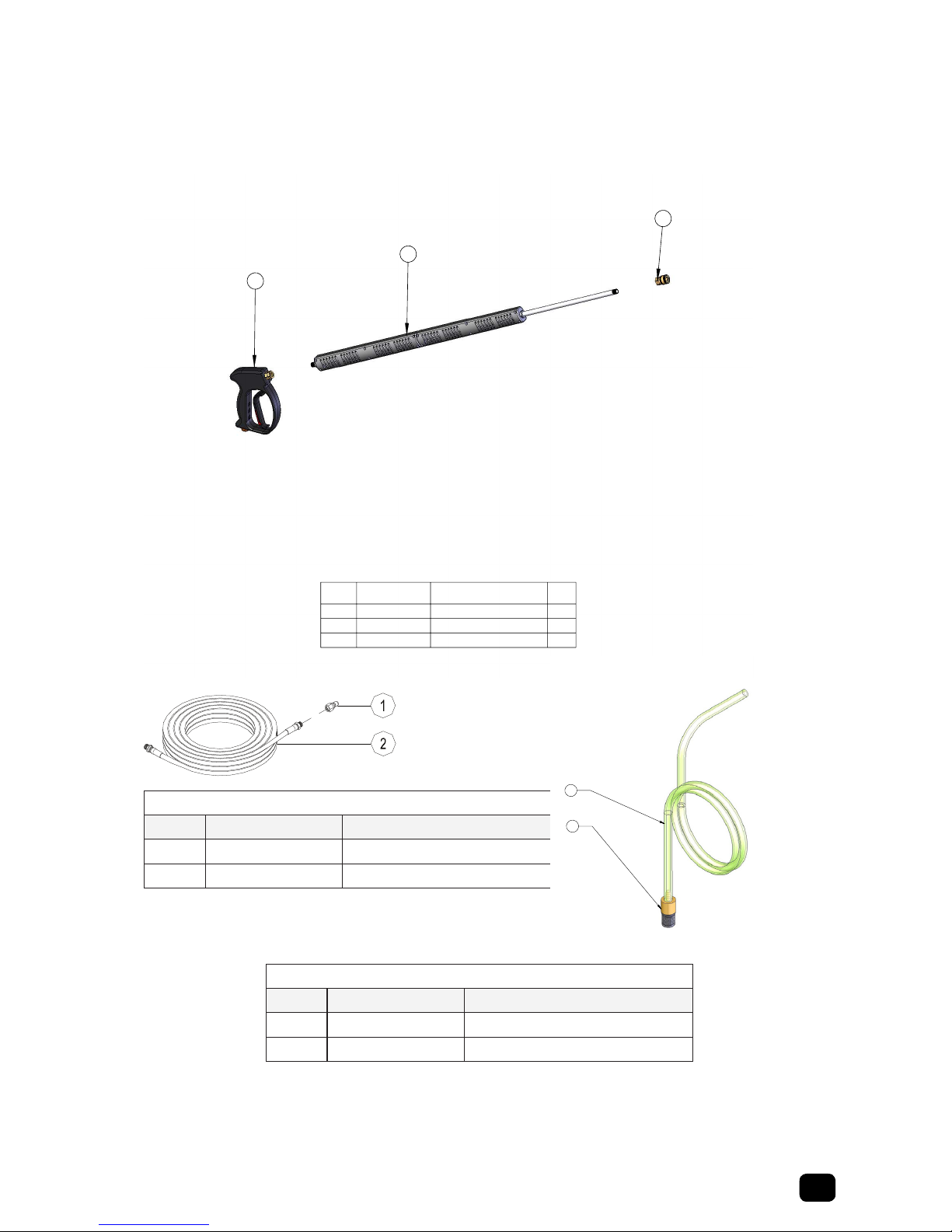
PART LISTS
ITEM PART NUMBER PART DESCRIPTION QTY.
1 C07-01300-08 O-RING - 1/16CS X 5/16ID 1
2 C07-01425 FILTER, WATER 1
3 J06-00121-07 O-RING - 3/32 CS X 1/8 ID 1
4 J06-00121-15 BALL, SS 5/16 1
5 J06-00132-19 SCREW, SELF TAP - 3.5MM X 18MM 7
6 J06-00158-01 FITTING, DISCHARGE - 1/4 FNPT 1
7 J06-00158-02 PIN, TRIGGER - 5MM X 27.5MM 1
8 J06-00158-03 CAM 1
9 J06-00158-04 TRIGGER 1
10 J06-00158-05 LATCH, SAFETY 1
11 J06-00158-06 FITTING, INLET - 3/8 FNPT 1
12 J06-00158-08A SEAT, VALVE 1
13 J06-00158-09 WASHER, FLAT 1
14 J06-00158-10 WASHER, FLAT - BRASS 1
15 J06-00158-11 HOUSING, VALVE 1
16 J06-00158-12A RETAINER, VALVE 1
17 J06-00158-13 SPRING, COMPRESSION 1
18 J06-00158-14 PIN, VALVE - 4MM X 44MM 1
19 J06-99158A HOUSING, HANDLE 1
REPAIR INSTRUCTIONS
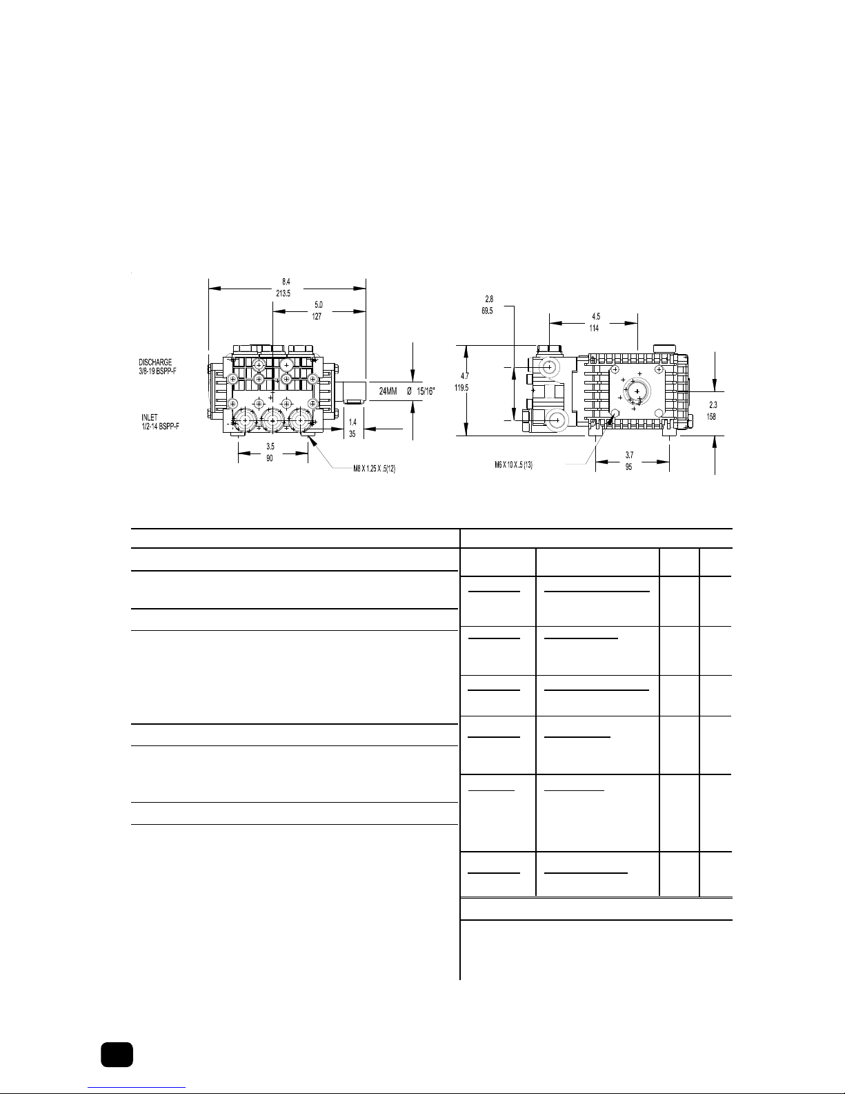
SPECIFICATIONS 23467
1
BEVEL SIDE
TOWARDS BALL DISHED SIDE
TOWARDS BALL
KIT, REPAIR PART - NUMBER J06-99158C
5
BREAKDOWN, GUN - TRIGGER
EXPLODED VIEW - P/N J06-00158
16
17
2
4
1
12 18 13 3
14
15
6
19 5
9
10
7
8
19
MAXIMUM VOLUME..............10.0 GPM / 37.9 LPM
MAXIMUM PERSSURE.........5000 PSI / 344.7 BAR
RATED TEMPERATURE....................300 F / 150 C
WEIGHT........................................1.8 LBS. / 0.8 KG
INLET .........................................3/8" NPT FEMALE
OUTLET......................................1/4" NPT FEMALE
YG3500
WARNING:
DO NOT USE ACID CONCENTRATES
THROUGH THE GUN
WARNING:
Never secure trigger gun in an open
postion (trigger pulled back) by
means other than the operator's hand.
Bodilay harm may occur if the operator
loses control of the trigger gun.
CAUTION:
Always engage trigger safety latch
when not in use.

7
Pump Assembly
Pump Assembly
11
2
1621247
15
6
19
20
18
17
12
3
1
5
13
25
9
4
10
14
4
22
8
ASSEMBLY, PUMP
9/11/2008
ITEM NO.
PART NUMBER
PART DESCRIPTION
QTY.
1
C03-00810
VALVE, AIR
1
2
C07-03700X
VALVE, UNLOADER (SILVER)
1
3
E04-00001-58
BUSHING, PIPE
1
4
E04-00005-48
BUSHING, PIPE
2
5
E07-00001-4
CROSS, PIPE
1
6
E08-00006-48
ELBOW, PIPE
1
7
E08-00011-58
ELBOW, PIPE
1
8
E09-00003-2
PLUG, PIPE
1
9
E10-00005-4
TEE, PIPE
1
10
E13-00010-2
NIPPLE, PIPE
1
11
E14-00010-68
NIPPLE, 3/8MNPT-CLOSE PS PIPE SCH80
1
12
E15-00010-48
NIPPLE, BRASS 1/2"
1
13
E15-00025-48
NIPPLE, BRASS 1/2"
1
14
F04-00761
SWITCH, VACCUM
1
15
K21-02214-1/4
ASSEMBLY, HOSE-OIL, DRAIN
1
16
K33-01300
HOSE, WATER - 3/8 X 13"
1
17
N07-00180
PUMP, WATER - 4PGM @ 2500PSI
1
18
N07-20046-P
MOUNT, PUMP
1
19
R03-00674
PULLEY, V
1
20
R04-00001
BUSHING, PULLEY
1
21
W02-00032
CLAMP, HOSE
2
22
W02-10016-8
BARB, HOSE
1
23
W02-10030-8
BARB, HOSE
1
24
W02-10040-8
BARB, HOSE
1
25
W02-10057-8
BARB, HOSE
1

8Pump Breakdown
Pump,Water
N07-00016
10-03-08 Z08-03934
PUMP, WATER
DIMENSIONS - P/N N07-00180
PERFORMANCE
DISCHARGE VOLUME.................................................. 4 GPM / 15.1 LPM
PUMP HEAD PRESSURE............................................ 2500 PSI / 172 BAR
GENERAL
CRANKSHAFT ROTATION.CLOCKWISE AND COUNTERCLOCKWISE
MAXIMUM SPEED............................................................. 1450 / 1750 RPM
MAXIMUM PUMPED FLUID TEMPERATURE............................ 165°F / 74°C
INLET PRESSURE -9 IN HG@75°F TO 116 PSI / -0.3 BAR@24°C TO 8 BAR
WEIGHT .......................................................................... 19.0 LBS / 8.6 KG
LUBRICATION
OIL CAHNGE INTERVA..........AFTER FIRST 50 HRS THEN AFTER 500 HRS
OIL TYPE .......................................SAE 20 OR SAE 30 (NON DETERGENT)
CRANKCASE CAPACITY .................................................4.0 FL OZ / 0.4LT
TORQUE
VALVE PLUG ...................................................... 73.7 FT LBS / 10.7 KG M
MOUNT TO CRANKCASE ......................................14.7 FT LBS / 2.0 KG M
REAR CRANKCASE COVER TO CARNKCASE ....... 7.3 FT LBS / 1.0 KG M
*HEAD TO CRANKCASE .......................................14.7 FT LBS / 2.0 KG M
*NOTE: When plunger nut is removed, it is important you install a
new copper washer and flinger washer to ensure proper fit and
seal of ceramic plunger. each time plunger screw is torqued, copper
washers conform to plunger. If same copper washers are used,
plunger cracking or poor seal may result.
TX1813S17
ACCESSORIES
Oil - Case - (6) One Pint Bottles................ p/n N07-0ILCA
Oil - Bottle - (1) One Pint Bottle.............. p/n N07-0ILCA-1
Oil - Case - (24) One Pint Bottles............ p/n N07-0ILCA-2
PART NO. DESCRIPTION ITEM QTY
N07-99123 VALVE ASSEMBLIES
ASS’Y, CHECK VALVE 36 6
0-RING 26A
N07-99124 VALVE PLUGS
PLUG 38 6
0-RING 27 6
N07-99159 CROSSHEAD SEALS
SEAL, CROSSHEAD 45 3
N07-99161 V-PACKINGS
SEAL, WATER -18 MM 26 3
PACKING, V-18MM 37 3
N07-99167 V-PACKINGS
SEAL, WATER - 18MM 26 1
PACKING, V - 18MM 37 1
REATINER, SEAL- 24 1
N07-99163 SEAL RETAINER
RETAINER, SEAL 24 3
SPECIFICATIONS PARTS PACKAGES
Parts List
Item p/n Description Item p/n Description
1 N07-20018 Screw, Cap 24 N07-98083 Retainer, Seal
2 N07-20019 Retainer, Bearing 25 N07-98016 O-Ring
3 N07-40029 Cover, Crankshaft 26 N07-98030 Seal, Water – 18mm
4 N07-20021 O-Ring 27 N07-99163 Adapter, Female – Front 18mm
5 N07-20022 Bearing, Roller 28 N07-98084 Packing, V – High Press 18mm
6 N07-20024 Dipstick, Oil 29 N07-20049 Plug, Pipe
7 N07-98023 Crankcase 30 N07-20050 Plug, Pipe
8 N07-98038 Crosshead 31 N07-20051 Washer, Flat
9 N07-98034 Rod, Connecting 32 N07-20011 Washer, Flat
10 N07-29026 O-Ring 33 N07-98001 Head, Pump – Brass
11 N07-98026 Cover, Rear 34 N07-20003 Washer, Flat
12 N07-20027 Screw, Cap 35 N07-98002 Screw, Cap – 8mm x 65mm
13 N07-98029 Indicator, Oil Level 36 N07-99123 Kit, Valve Assembly
14 N07-80009 O-Ring 37 N07-20004 O-Ring
15 N07-20030 Plug, Pipe 37A N07-20009 O-Ring
16 N07-20028 O-Ring 38 N07-47010 Plug, Pipe
17 N07-98032 Pin, Crosshead 39 N07-12056 Nut, Hex
18 N07-17931 Crankshaft 40 N07-98085 Adapter, Plunger
19 N07-98033 Key 41 N07-44040 Plunger – 18mm
20 N07-98045 Seal, Oil 42 N07-20039 Washer, Flinger – Copper
21 N07-20046 Mount, Pump 43 N07-98028 O-Ring
22 N07-20047 Washer, Lock 44 F04-76509 Ring, Anti-Extrusion
23 N07-20048 Screw, Cap 45 N07-99159 Kit, Crosshead
N07-00180

9
Pump Breakdown
Parts List
Item p/n Description Item p/n Description
1 N07-20018 Screw, Cap 24 N07-98083 Retainer, Seal
2 N07-20019 Retainer, Bearing 25 N07-98016 O-Ring
3 N07-40029 Cover, Crankshaft 26 N07-98030 Seal, Water – 18mm
4 N07-20021 O-Ring 27 N07-99163 Adapter, Female – Front 18mm
5 N07-20022 Bearing, Roller 28 N07-98084 Packing, V – High Press 18mm
6 N07-20024 Dipstick, Oil 29 N07-20049 Plug, Pipe
7 N07-98023 Crankcase 30 N07-20050 Plug, Pipe
8 N07-98038 Crosshead 31 N07-20051 Washer, Flat
9 N07-98034 Rod, Connecting 32 N07-20011 Washer, Flat
10 N07-29026 O-Ring 33 N07-98001 Head, Pump – Brass
11 N07-98026 Cover, Rear 34 N07-20003 Washer, Flat
12 N07-20027 Screw, Cap 35 N07-98002 Screw, Cap – 8mm x 65mm
13 N07-98029 Indicator, Oil Level 36 N07-99123 Kit, Valve Assembly
14 N07-80009 O-Ring 37 N07-20004 O-Ring
15 N07-20030 Plug, Pipe 37A N07-20009 O-Ring
16 N07-20028 O-Ring 38 N07-47010 Plug, Pipe
17 N07-98032 Pin, Crosshead 39 N07-12056 Nut, Hex
18 N07-17931 Crankshaft 40 N07-98085 Adapter, Plunger
19 N07-98033 Key 41 N07-44040 Plunger – 18mm
20 N07-98045 Seal, Oil 42 N07-20039 Washer, Flinger – Copper
21 N07-20046 Mount, Pump 43 N07-98028 O-Ring
22 N07-20047 Washer, Lock 44 F04-76509 Ring, Anti-Extrusion
23 N07-20048 Screw, Cap 45 N07-99159 Kit, Crosshead
N07-00180

10 Pump Maintenance
6
7
2
6
3
1
General
PACKING EXTRACTION KIT P/N Z09-00028
COMPLETE TOOL KIT P/N Z09-00021
Valve Service
1. Remove the plugs holding the valve assemblies.
2. Remove and discard o-rings from the plugs. Clean plugs with
solvent or soap and water. Allow to dry.
3. Using needle nose pliers, ngers, or hook shaped tool,
remove the valve assemblies from the head. Remove and
discard the o-rings from the valve assemblies and/or head.
Examine each valve assembly and discard damaged parts.
Refer to the PUMP BREAKDOWN for part numbers of any
replacement items.
4. Clean any accumulated debris from the valve cavities and
ush with water.
5. Wash the valve assemblies in clean water and rinse. While
still wet, test each valve assembly by sucking on the valve
seat. A properly sealing valve will allow a good vacuum to
be developed and maintained, while a malfunctioning valve
will not. Good valve assemblies should be set aside for
installation in step 7.
6. Malfunctioning valve assemblies must be replaced.
7. Lubricate a new o-ring with the pump crankcase oil and install
into valve cavity in the head. Install a good valve assembly
into the cavity as illustrated.
8. Lubricate a new o-ring with pump crankcase oil and place on
a plug cleaned in step 2 above.
9. Install a plug into the pump head. Tighten plug by hand.
10. Torque the plug to the value indicated in the TORQUE section
of the pump specications.
11. Repeat steps 7 through 11 for remaining valve assemblies.
Head Removal
1. Remove the cap screws holding the pump head to the
crankcase. A metric tool is required for this step. Be careful
not to lose the washer on each cap screw.
2. Remove the head by rotating the crankshaft and tapping
the head away from the crankcase with a soft mallet. Keep
rear surface of the head parallel to the front surface of the
crankcase to prevent binding on the plungers.
3. Once the head is removed, protect the plungers from damage.
Plunger Service
1. Remove pump head per HEAD REMOVAL.
2. Remove any packings and retainers left on the plungers by
pulling them straight off.
Pump Maintenance

11
Pump Maintenance
3. Examine each plunger, looking for a smooth surface free of
any scoring, cracks, or pitting. Any defective plungers should
be removed per PLUNGER REMOVAL.
4. Discard and replace any defective plungers.
5. Reinstall the plunger per PLUNGER INSTALLATION.
6. Reinstall head per HEAD INSTALLATION.
Plunger Removal
NOTE: When the plunger screw is removed, it is important to install new
o-ring, anti-extrusion, and copper washers.
1. When the plunger screw is removed, it is important to install a
new o-ring, anti-extrusion, and copper washers.
2. Remove the plunger retaining screw by turning
counterclockwise. Remove and replace copper washer.
3. Remove and discard o-ring and anti-extrusion ring from
retainer screw.
4. Remove the plunger from the cross head and examine it for
cracks, scoring, or pitting.
5. Remove and discard copper inger washer, clean with solvent
and allow to dry.
Plunger Installation
1. Install the copper inger washer onto the cross head.
2. Slide the plunger onto the crosshead.
3. Lubricate an o-ring with crankcase oil and install into the
groove on the plunger screw. Install the anti-extrusion ring

12 Pump Maintenance
into the groove next to the o-ring. NOTE: The o-ring should
be nearest the screw head and the anti-extrusion ring nearest
the threads.
4. Apply a drop of thread sealant to the threads of the retainer
screw.
5. Thread the plunger retainer screw into the cross head making
sure the copper at washer is installed onto the screw.
6. Torque the plunger retainer screw to the value indicated in the
torque section of the pump specications.
Packing Service
1. Remove the head per PUMP HEAD REMOVAL.
2. Remove any packings and female adapters left on the
plungers by pulling them straight off. Insert proper packing
extractor onto the extractor hammer. Insert packing extractor
and tool through the packings and adapters remaining in the
head. Tighten the hammer and remove the remaining items
in the head. Remove packings and o-rings from adapters.
Discard the o-rings and packings.
3. Clean the packing canities in the head and rinse with clean
water.
4. Clean exposed plungers. Clean male and female adapters
with soap and water and allow it to dry.
5. Examine male and female adapters, discard worn items. Trial
t the female adapters into the head checking for binding or
damage. Discard and replace damaged items
6. Lubricate packing cavities in the head and all packings and
adapters with pump crankcase oil.
7. Lay head on the bench with packing cavities up. Install one
male adapter in each cavity with the at side down.
8. Install one v-packing into each cavity with the lips pointing
down. A packing insertion tool of the appropriate size is
recommended for this operation.
9. Install the re-stop ring with the lips pointing down.
10. Install a front female adapter into each cavity with the at side
up. Make certain the adapter goes all the way down into the
cavity.
11. Install the low pressure packing with the at side down.
12. Install the rear female adapter into each cavity with the lips
pointing down.
13. Lubricate o-rings with pump crankcase oil and install one into
the groove of each adapter.
14. Install one adapter and o-ring into each cavity with the at
side up. Each adapter and o-ring assembly should push into
the head to approximately 1/16 inch of being ush with the
surface of the head. Only hand pressure should be required
to perform this operation. This step is VERY IMPORTANT.
If the rear female adapter does not t is obtained, proceed
to step 16. If a proper t is not obtained, remove the female

13
Pump Maintenance
5
3
1
7
6
4
2
8
7
adapters from the offending cavity and reinstall items per steps 8 through 15.
15. Install head per HEAD INSTALLATION.
Head Installation
1. Prepare pump head per instructions in PACKING SERVICE.
2. Rotate the plungers so the outer plungers are projecting the same distance from the crankcase.
3. Lubricate the exposed plungers with crankcase oil.
4. Start the head onto the plungers and, using a soft mallet, tap the head evenly until it comes in
contact with the crankcase.
5. Start the cap screws through the head and into the crankcase. Do not forget the lock washer on
each screw.
6. Tighten all cap screws by hand.
7. Torque the cap screws to the value indicated in the TORQUE section of PUMP SPECIFICATIONS.
Torque the cap screws in the order listed below.

14 Pump Maintenance Records
Oil Change
Month/Day/Year Operating Hours Oil Brand & Type
Pump Service
Month/Day/Year Operating Hours Type of Service
Pump Maintenance Record

15
Unloader Valve Breakdown
Unloader Valve
C07-03700X, C07-03800X, C07-05700X
Unloading Adjustment
1. Install an appropriate pressure gauge in
pump head outlet. The gauge should
have a range twice the operating
pressure.
2. Loosen nut (Item 23) and turn the
knob (Item 26) counter clockwise until
minimum spring tension.
3. Open the trigger gun, start the pump,
and observe pressure gauge reading.
Slowly tighten the knob.
4. Close and open the trigger gun to check
unloading pressure and bypass function
of the unloader valve. The unloading
pressure should not exceed operating
pressure more than 400 PSI.
5. Lock the setting by tightening the nut
(Item 23)
Note: Once the operating pressure is reached,
turning the knob clockwise will increase the
unloading pressure only.
Specications
Maximum Flow 7.8 gal/m / 30 L/m
Max Unloading Press
C07-05700X 2900 psi / 200 bar
C07-03700X 3650 psi / 252 bar
C07-03800X 4350 psi / 300 bar
Maximum Temperature 190˚F / 88˚C
Weight 2.1 lbs / 0.91 kg
Bypass 1/4 FNPT
Inlet & Discharge 3/8 FNPT
Item Part Number Description Qty Kit
C07-03700X
C07-03800X
C07-05700X
1C07-03700X-01 Piston 1 *
2C07-03700-15 Pin, Roll 1 *
3C07-03700-28 Ring, Anti-Extrusion 2 *
4C07-03700-29 O-Ring – 3/32 x 7/16ID x 3043 1 *
5C07-03700X-02 Housing, Unloader – 3/8” 1
6C07-0370019B Gasket, Washer – 14 x 8.3 x 1.5 1
7C07-0370019A Plug – 3/8” 1
8C07-03700-6B Gasket, Washer – 11.4 x 6.5 x 1.5 1
9C07-03700-6A Plug – 1/4” 1
10 C07-03700-2 O-Ring – 11/16ID 3 *
11 C07-02000-20 O-Ring 1 *
12 C07-03700-4 Orice, Shutter 1 *
13 C07-03700-3 Spring, Compression 1 *
14 C07-03700X-03 Fitting, Outlet 1
15 N07-20028 O-Ring – 1/16CS x 7/16ID 1 *
16 C07-03700X-04 Guide, Piston – SS 1 *
17 C07-03700X-05 Ball, SS – 11/32 1
18 C07-03700-23 Spring, Compression 1
19 C07-03700X-06 Guide, Ball 1
20 C07-03700-12 Ring, Anti-Extrusion 2 *
21 8RS6-000SV01 O-Ring – 1/16CS x 1/2ID 1 *
22 C07-03700X-07 Guide, Piston 1
23 C07-03700-7 Nut, Lock – M8 2
24
C07-05700X-08 Spring – yellow 2900 psi 1
C07-03700X-08 Spring – grey 3650 psi 1
C07-03800X-08 Spring – black 4350 psi 1
25 C07-03700X-09 Follower, Spring 1
26 C07-03700X-10 Knob, Adjustment 1
27
C07-05700X-11 Cover, Knob – orange 2900 psi 1
C07-03700X-11 Cover, Knob – blue 3650 psi 1
C07-03800X-11 Cover, Knob – grey 4350 psi 1
C07-03700XK Kit, Repair - Parts Package
1/17/2008
Unloader Valve Breakdown

16 Float Tank Assembly
Float Tank Assembly
4
2
1
7
8
3
6
5
ASSEMBLY, TANK - FLOAT
ITEM
NO.
Part Number
PART DESCRIPTION
QTY.
1
2120-04120B
TANK, FLOAT
1
2
4120-10540
ASSEMBLY, RESTRICTOR
1
3
C03-00631
FLOAT VALVE
1
4
C04-00120
FILTER, SOAP SCREEN
1
5
C05-00271
WASHER, GARDEN HOSE
1
6
C05-00274
ADAPTER, GARDEN HOSE
1
7
E09-00002-P
PLUG, PIPE - NYLON
1
8
W02-10057-8
BARB, HOSE
1

17
Float Tank Assembly
3
5
4
6
8
9
10
17
15
14
1
12
7
13
16
11
2
18
PARTS LIST
VALVE, FLOAT - P/N C03-00631
SPECIFICATIONS
8/8/2008
ITEM
NO. PART NUMBER PART DESCRIPTION QTY.
1 C03-00625-10 SCREW, WING - 10-32UNF 1
2 C03-00628 FLOAT, PLASTIC 1
3 C03-00631-01 NUT,HEX - 3/8FNPT 1
4 C03-00631-02 WASHER, FLAT - RUBBER 1
5 C03-00631-03 NIPPLE, BRASS - 3/8NPT 1
6 C03-00631-04 SEAT, VALVE-NYLON 1
7 C03-00631-05 HOUSING, VALVE 1
8 C03-00631-06 PISTON 1
9 C03-00631-07 ROD, PISTON-5/16CS X 1 1/4
PLASTIC 1
10 C03-00631-08 GUIDE, PISTON 1
11 C03-00631-10 SCREW, CAP 1
12 C03-00631-11 ARM, FLOAT 1
13 C03-00631-14 NUT, HEX - BRASS 1
14 C03-00631-16 LEVER - BRASS 1
15 C03-00631-17 KEY, COTTER 1
16 C03-00631-18 NIPPLE, TOE 1
17 C03-0631-09 NUT, RETAINER 1
18 H05-18700 WASHER, FLAT 1
MAXIMUM VOLUME.............................7 GPM / 26 LPM
MAXIMUM PRESSURE........................140 PSI / 10 BAR
MAXIMUM TEMPERATURE ......................140 F/60 C
PORT SIZE - INLET..........................................3/8" NPT
DIMENSIONS...11.4 X 4.1 X 2.8 IN / 290 X 104 X 71MM
WEIGHT...................................................0.6 LB / 0.3 KG
HOUSING MATERIAL .........................................BRASS
O-RING MATERIAL............................................BUNA-N

18 Burner Assembly
Burner Assembly
1
4
2
3
6
7
8
ASSEMBLY, BURNER
ITEM
NO.
Part Number
PART DESCRIPTION
Defaul
t/QTY.
1
AS16-01204-PB
BRACKET, TRANSFORMER
1
2
E08-00006-2
ELBOW, PIPE
1
3
E13-00010-2
NIPPLE, PIPE - 1/4"
1
4
H04-19011
SCREW, SELF TAP
2
5
V00-17318
BURNER, OIL - 230V
1
6
V04-0031
FILTER , FUEL
1
7
W02-10019-8
BARB, HOSE
1
8
W02-10031
BARB, HOSE
1

19
Burner Assembly
Maintenance Procedures
Priming the machine
Shut off the fuel tank valves. Spin off the clear bowl, ll with
clean fuel and coat the round gasket (3) with fuel. Reinstall the
clear bowl and tighten ¼ to 1/3 turns after the gasket contacts
the upper housing. Turn on the fuel tank valves. Start the
machine and check that there are no leaks.
Draining water
Check the collection bowl daily. Drain off water
contaminants by unscrewing the clear bowl turning counter-
clockwise. Start the machine and allow air to purge from the
fuel system prior to operating the equipment.
Element replacement frequency
Frequency of element replacement is determined by
contamination level in the fuel. Replace the element every 500
hours.
Note: Foul smelling diesel fuel is an indication of
microbiological contamination. A change in fuel source is
recommended. Always carry a spare lter element as one
tank full of contaminated fuel will plug the fuel lter element
prematurely.
Element replacement procedure
1. Shut off the fuel tank valves.
2. Unscrew the clear bowl turning counter-clockwise.
3. Remove and discard the lter element.
4. Follow listed procedures under “PRIMING.”
2
3
1
4
FILTER, FUEL - 1/4F X 1/4F
p/n: V04-00314
2/26/2010
ITEM
NO. PART NUMBER PART DESCRIPTION QTY.
1 V04-00314-1 HOUSING, UPPER-1/4F X 1/4F
ALUMINUM 1
2 V04-00314-2 O-RING, 1
3 V04-00314-3 SCREEN,FILTER-SS ELEMENT 1
4 V04-00314-4 BOWL, FILTER-CLEAR
PLASTIC 1
Trouble Possible Cause Remedy
1. Fuel bowl leaking. A. Deteriorated gasket.
B. Housing Cracked.
C. Bowl rim cracked, nicked, or
scratched.
D. Gasket missing.
E. Loose Fuel Bowl.
A. Remove and Replace Gasket.
B. Remove and Replace Housing.
C. Remove and Replace Bowl.
D. Replace Gasket.
E. Tighten Fuel Bowl Onto Filter.
2. Air leaking into system
(indicated by air bubbles in
bowl during operation).
A. Cracked Component.
B. Loose Filter bowl.
A. Inspect Filter Bowl, Filter Housing, and
Gasket.
B. Tighten Fuel Bowl Onto Fuel Filter.

20 Buner Breakdown
Burner Breakdown
Table of contents
Other ZEP Pressure Washer manuals