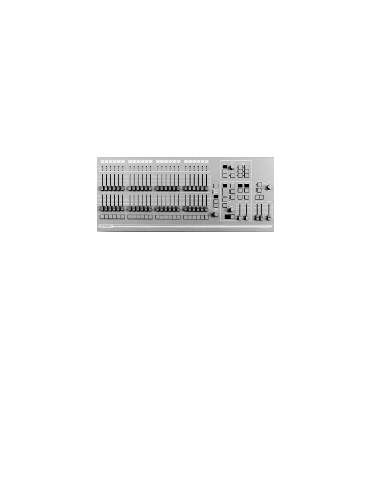
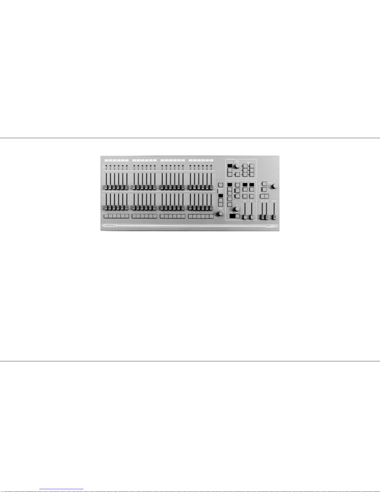
Setting up the Desk for Programming
1 Set ALL faders at zero, set Grand Master to
full.
2 Turn the Mode switch to Program. Program
light will come on.
3 Push the Master A fader to full.
4 Check memory Page is showing ‘1’.
Programming a Memory
1 Select the memory Page required using the
page ‘+’ and ‘-’ controls.
2 Press the Flash/Preview button to select the
memory (1-24) that you wish to program. The
Preview lights will show any previously
programmed scene; the Preview light of the
memory selected will flash slowly and the
Page display will change from 1 (for example)
to P1, a reminder that the page selected is
being previewed.
3 Set up a scene on the Outputs using Preset
A, other Memory Masters or a static Step
from an Effect Pattern.
4 Briefly press the Program button to record
the output levels in to memory. The new
memory is immediately displayed on the
yellow Preview leds, to verify that this
information has been recorded.
5 Repeat steps 1 to 4 to program additional
memories.
Clearing a Memory
1 Select a memory to be programmed or
program a new memory as described above.
2 Set the Grand Master down to zero.
3 Briefly press Program to clear the memory by
storing a scene with all levels at 0. Any
preview lights that were on go off.
Blind Programming
This is possible using the Level Match feature
described on page 11.
Editing (Using Level Match in Program)
1 Set up and record a scene in memory. Leave
the desk in Program.
2 Move all faders to 0, leave Grand Master at
10.
3 Press the memory Flash/Preview button of
the memory you want to edit and hold it
down until the Preview lights flash to preview
the scene that was recorded.
The channel Preview lights will flash quickly
on any channels where the channel level on
Preset A needs to be decreased to match the
programmed level. The channel Preview
lights will flash slowly on any channel where
the channel level on Preset A needs to be
increased to match the programmed level.
To see the level on the output leds / dimmers
move the Master A to full.
4 To edit any channels, adjust the appropriate
Preset A channel fader until the associated
channel Preview light is on continuously.
Be careful! When the Preset A fader level
is at the recorded level, the fader ‘catches’
the level and then has LIVE control.
5 Now move the fader to the required level.
The preview light is still on continuously, this
shows the fader and memory are at the same
level. The memory has now been edited -
simply cancel Level Match by pressing the
Flash/Preview button once.
HINTS
*
Programming Appears Not To Work
Check that the Grand Master and Master A are up to full,
since with Master A at zero, a blank memory will be
programmed. Simply fade up the Grand Master or Master A
and reprogram the memory.
*
The scene recorded is not the scene that was
wanted.
Check that none of the Memory Masters or the Effects Master
were up whilst you were programming. If any of these
masters were on, this will be shown on the Output Lights and
the memory that will be recorded will be the mixture of levels
set by Preset A and levels set by the Memory Masters that
were up. This is an essential feature of the desk.
*
Reprogramming a Memory
If the memory chosen is not empty (shown by the preview
lights coming on), pressing the Program button will overwrite
any previous information with the current settings of Preset A;
the old memory will be lost.
*
Changing the Memory Selected
To change the memory that you have selected within a Page,
simply press another memory Flash/Preview button. To
remove the memory preview information from the Preview
lights in Run, press the Flash/Preview button of the memory
once again.
*
‘PC’ in the Page Display
When ‘PC’ is shown (Preview Ch), this means that ‘Ch’ was
showing in the Page display when the memory was selected.
Pressing the Flash button again will return the display to ‘1’ or
using the Page +/- buttons will move to the correct Page
required.
*
Flash Function
In Program Mode the Flash Function is disabled.
*
Page CH:
Is a preprogrammed memory page where Memory Master 1
is programmed with Channel 1 and Memory Master 2s is
programmed with Channel 2 etc.
p9/4
Programming the Memory
7359700/p9/4 Page 9