ZF 400 Series User manual

ZF 400 Family
Operating Instructions

MANUALE DI RIPARAZIONE
Copyright © ZF Padova S.r.l.
This document is protected by copyright. Complete or partial reproduction
or dissemination of this document is prohibited without the consent of Z
F Friedrichshafen AG. Infringements lead to civil and criminal prosecution.
This document is a translation of the Italian original.

3
Index
EN_3224.758.102d_2021_12
1 Introduction .................................................................................................................... 5
1.1 Conversion table ........................................................................................................................... 5
1.2 Conventions for safety information in text ..................................................................................... 6
1.3 Responsibilities ............................................................................................................................. 7
1.3.1 Manufacturer's address and contact info ...................................................................................................... 7
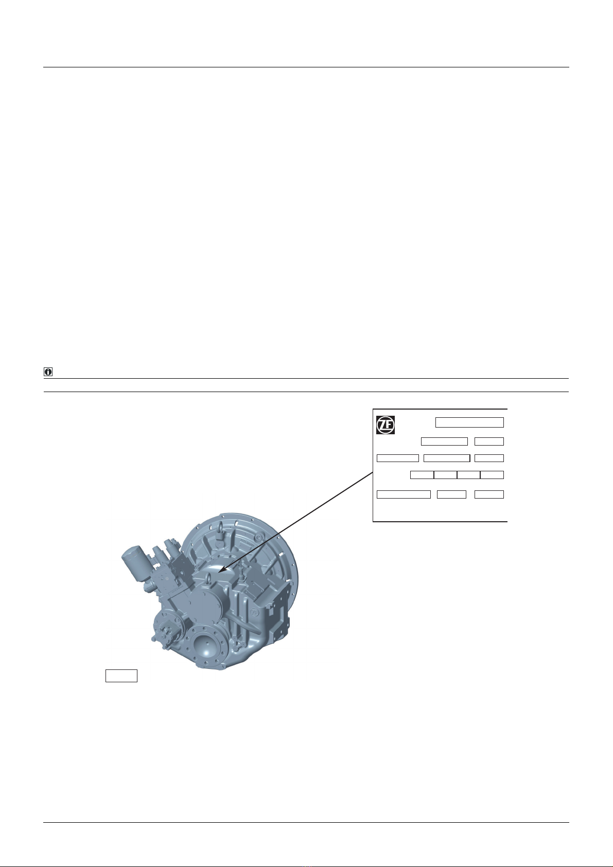
1.4 Reverse transmission identification ............................................................................................... 7
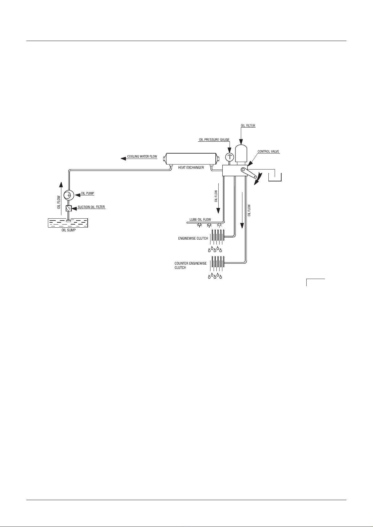
1.5 Operating principles...................................................................................................................... 8
1.6 Main subgroups .......................................................................................................................... 10
1.6.1 ZF 400 A .................................................................................................................................................... 10
1.6.2 ZF 400 IV ................................................................................................................................................... 11
1.6.3 ZF 400 V .................................................................................................................................................... 12
1.6.4 ZF 400 ....................................................................................................................................................... 13
1.6.5 Mechanical trolling valve (MTV).................................................................................................................. 14
1.6.6 Electrical trolling valve (ETV)....................................................................................................................... 15
1.6.7 Remote controls for oil control block .......................................................................................................... 15
1.6.8 Tugging...................................................................................................................................................... 15
2 Technical data .............................................................................................................. 16
2.1 Types of oil ................................................................................................................................. 16
2.1.1 Lubricant class 04A .................................................................................................................................... 16
2.1.2 Lubricant class 04B .................................................................................................................................... 16
2.1.3 Lubricant class 04C .................................................................................................................................... 16
3 Emergency devices ...................................................................................................... 17
3.1 Electrical circuit failure ................................................................................................................ 17
4 Installation.................................................................................................................... 18
4.1 Connection of the propeller axle ................................................................................................. 18
4.2 V-DRIVE reverse transmission ..................................................................................................... 19
4.3 Alignment method ...................................................................................................................... 19
4.3.1 Alignment method with parallel-face flanges.............................................................................................. 19
4.3.2 Alignment method with tailstock shafts ...................................................................................................... 20
5 Maintenance................................................................................................................. 21
5.1 Maintenance schedule................................................................................................................ 21
5.2 Oil level inspection...................................................................................................................... 23
5.3 Oil change .................................................................................................................................. 23
5.4 Intake filter check........................................................................................................................ 24
5.5 Oil filter replacement .................................................................................................................. 24
5.6 Remote control adjustment ......................................................................................................... 25
6 Troubleshooting guide ................................................................................................. 26
7 Service centers............................................................................................................. 27
8 Maintenance certificates ............................................................................................. 28

4
Index
EN_3224.758.102d_2021_12

Introduction
5
EN_3224.758.102d_2021_12
1 Introduction
This document is to be intended only as a support material for the design and analysis of the Vessel Designer and Shi-
pyard in their role of unique Responsible of the final performance analysis, design, selection and decisions. ZF Padova
S.r.l. accept no liability for lack of performance for any expressed or unexpressed result. In no way, this document is
to be intended as a performance and/or commercial promise. ZF Padova S.r.l. keeps the right to modify procedures,
shapes, equipment, optionals, material, etc. mentioned or shown in the attached figures. Also, some mentioned equi-
pment might be optional. The actual scope of supply will be limited to that mentioned in the offers issued by ZF Sales
Dept
Notice
Read this handbook before proceeding with the installation. The following symbols are used to highlight important in-
formation on technical reliability and safety:
1.1 Conversion table
This symbol denotes a procedure that could result in physical injury to the operator or to other persons in the
vicinity if not followed correctly.
This symbol denotes a procedure that could damage the gearbox or associated equipment if not followed cor-
rectly.
NOTE:
When this symbol is displayed, the text alongside contains important information.
S.I. International System (of Units) Others
1 (mm) = 0.03937 (in)
10 (mm) = 0.3937 (in)
25.4 (mm) = 1 (in)
64.516 (cm2) = 1 (sq. in)
1 (m2) = 1550 (sq. in)
16.387 (cm3) = 1 (cu. in)
0.473 (dm3) = 1 (U.S. pint)
1 (l) = 61.02 (cu. in)
1 (l) = 0.2642 (U.S. gal)
1.772 (g) = 1 (oz)
0.4536 (kg) = 1 (lb)
0.00070308 (kg/mm2) = 1 (lb/sq. in)
1 (bar) = 14.51 (psi)
1 (kg·m) = 7.246 (lb·ft)
30.48 (cm) = 1 (feet)
DANGER
CAUTION

Introduction
6EN_3224.758.102d_2021_12
1.2 Conventions for safety information in text
The following conventions apply for the safety information in these Operating Instructions:
• Ensure you read and understand all warnings prior to commissioning or repairing the product!
• Pass on all safety information to personnel involved in operating, maintenance, repair and transport!
Describes a dangerous situation that can lead to serious injuries or death when not avoided.
Describes a dangerous situation that can lead to minor o moderate injuries when not avoided.
Describe a situation which can lead material damage when not avoided.
NOTE:
Serves to draw attention to special procedures, methods, information, use of aids and tools, etc. This document specially highlights
safety information according to US standard ANSI Z535 by marking the text with the above signal words according to the degree
of danger.
DANGER
WARNING
CAUTION
NOTICE

Introduction
7
EN_3224.758.102d_2021_12
1.3 Responsibilities
The customer/operator is responsible for the maintenance checks described in this manual to ensure the proper ope-
ration of the reverse transmission in fully safe conditions.
1.3.1 Manufacturer's address and contact info
All gearboxes supplied by ZF Padova S.r.l. are accompanied by the relative operating manual.
Further copies of this manual or of other technical documentation can be obtained from:
ZF Padova S.r.l.
Via Penghe 48,
35010 Caselle di Selvazzano (PD), Italy
Tel. +39 049 8299485
Fax +39 049 8299560
1.4 Reverse transmission identification
The identification plate is affixed to the reverse transmission. Before proceeding with the installation, we recommend
reading the instruction manual.
For important information regarding technical reliability and safety, the following conventions have been adopted:
NOTE:
The notes contain important information, to which the user must pay careful attention.
SERIAL No RATIO
TYPE
OIL TYPE
OIL CHANGE: after first 50 hours of operation and every
1000 hours or 12 months, wichever occurs first.
CHECK OIL LEVEL WEEKLY
OIL
CAPACITY (dm3)
CLUTCH OIL
PRESSURE(bar)
CUSTOMER No MASS DRY (Kg)
PART LIST No
ContinousMediumLightPleasure
Fig. 1

Introduction
8EN_3224.758.102d_2021_12
1.5 Operating principles
The main functions of a marine reverse transmission include:
• coupling the engine with the propeller axle and reducing the propeller speed;
• inverting the direction of motion;
• interrupting the movement of the propeller shaft (idling mode).
Below is a simplified diagram of the hydraulics.
The marine gearbox allows for obtaining the following three types of operation:
Neutral
The output shaft (2) connected to the propeller axle does not transmit any rotation.
The clutches are disengaged.
Engine rotation
The output shaft (2) connected to the propeller axle rotates in the same direction as the input shaft (1).
Counter engine rotation
The output shaft (2) connected to the propeller axle rotates in the opposite direction to the input shaft (1).
The concordant and/or discordant motion transmission occurs with the transmission ratio indicated on the identifica-
tion plate.
The three operating modes are controlled by the oil control block (3) (mechanical or electrical).
Fig. 2

Introduction
9
EN_3224.758.102d_2021_12
E.R.
The rotation direction matches the engine rotation.
C.E.R.
The rotation direction is contrary to the engine rotation.
The reverse transmission can be supplied with or without accessories (heat exchanger, flexible coupling, brackets, trol-
ling valve).
The reverse transmission is supplied without oil.
In normal operating conditions, the direction reversals must be made with the engine at minimum power.
In case of emergency, the direction of motion can be reversed with the engine at full speed.
Motion reversals with the engine at full speed significantly reduce the working life of the clutches.
Before putting the reverse transmission into operation, the oil must be topped up and its level checked. (Refer
to section "Maintenance" (p. 21)).
Using the reverse transmission with too little oil can damage the gears.
Too much oil can cause the seals and bleed to leak and can considerably increase the operating temperature.
Intervene on the reverse transmission only when both the engine and the propeller are stationary.
ZF 400 A
Fig. 3
ZF 400 IV
ZF 400 V
CAUTION
DANGER

Introduction
10 EN_3224.758.102d_2021_12
1.6 Main subgroups
1.6.1 ZF 400 A
POS. DESCRIPTION
1PTOcover
2Outputshaft
3Drainplugs
4Rearhalf-carcass
5Fronthalf-carcass
6 Heat exchanger
7Liftingeyebolt
8 Level rod
9 Oil control block
10 Solenoid valve
11 Oil filter
12 Oil pump
13 Mesh filter
14 Load plug
15 Pressure socket
16 Bleed
17 M14x1.5 plug
ZF 400 A
15 16
17
3
3
7
2
1
4
5
6
7
8
9
13
11
14
12
14
10
11
Fig. 4

Introduction
11
EN_3224.758.102d_2021_12
1.6.2 ZF 400 IV
POS. DESCRIPTION
1PTOcover
2 Oil pump
3Outputshaft
4 Strainer / Screen filter
5Drainplugs
6 Rear half housing
7 Front half housing
8 Oil dipstick
9Breather
10 Oil cooler
11 Filler plug
12 Shift control linkage bracket
13 Control valve
14 Control valve lever
15 1/8 NPTF pressure connector
16 M14x1.5 plug
17 Lifting eyebolt
18 Oil filter
ZF 400 IV
11
12
6
6
5
4
2
16
1
17
814
14
15 13
3
3
7
7
9
2
17
17
18

Introduction
12 EN_3224.758.102d_2021_12
1.6.3 ZF 400 V
POS. DESCRIPTION
1PTOcover
2 Oil pump
3Outputshaft
4 Strainer / Screen filter
5Drainplugs
6 Rear half housing
7 Front half housing
8 Oil dipstick
9Breather
10 Oil cooler
11 Filler plug
12 Control valve
13 1/8 NPTF pressure connector
14 Oil filter
ZF 400 V
11
11
10
10
16
12
12
6
6
5
5
4
2
2
1
8
8
14
13
3
3
7
7
9
9

Introduction
13
EN_3224.758.102d_2021_12
1.6.4 ZF 400
POS. DESCRIPTION
1PTOcover
2Outputshaft
3Drainplugs
4Rearhalf-carcass
5Fronthalf-carcass
6 Heat exchanger
7Liftingeyebolt
8 Level rod
9 Oil control block
10 Solenoid valve
11 Oil filter
12 Oil pump
13 Mesh filter
14 Load plug
15 Pressure socket
16 Bleed
17 M14x1.5 plug

Introduction
14 EN_3224.758.102d_2021_12
1.6.5 Mechanical trolling valve (MTV)
The trolling valve is a device that allows for varying the speed of the propeller, regardless of the engine's rotation spe-
eds. The MTV is commonly applied in the following cases:
1. the watercraft's speed is too high even though the engine is at minimum power.
2. the rotation speed of the PTO must exceed the propeller's rotation speed.
• Maximum rotation speed = (max engine revolutions x 0.5) rpm, for engines with maximum rotation speed below
2000 rpm.
• Maximum rotation speed = (1000) rpm, for engines with maximum rotation speed above 2000 rpm.
Depending on the reverse transmission's reduction ratio, the propeller's dimensions and the features of the watercraft,
the actual rotation speed of the propeller can be reduced by a percentage varying between 30% and 70% of the useful
speed.
Recommended range of use: 60-80°C.
a. Clutch slipping
b. Clutch pressure
c. pressure gage fitting (15)
The MTV can be used in both directions of motion and the maximum usage speeds are:
NOTE:
Mode of use
Verify that the MTV is excluded before engaging the gear. After engaging the gear, gradually move the MTV lever until reaching the
desired maneuver speed.
The number of revolutions can be varied during operation in trolling mode within the limits mentioned above.
CAUTION
c (15)
Fig. 5
a
b

Introduction
15
EN_3224.758.102d_2021_12
1.6.6 Electrical trolling valve (ETV)
An electrical device with the same functions and mode of use as the MTV.
The ETV is activated by means of a proportional solenoid valve.
1.6.7 Remote controls for oil control block
1.6.8 Tugging
Tugging can be performed continuously for 8 hours. Check that the oil temperature does not exceed 80°C. When the
engine is off, the position of the operating lever is irrelevant.
When installing remote controls, make sure that the stroke of the lever, activated from the control on the brid-
ge, is suitable for reaching the limit switches.
If this condition is not met, the clutches may burn due to insufficient oil flow.
Do not perform any work on the transmission during tugging, as the propeller may rotate.
CAUTION
Fig. 6
DANGER

Technical data
16 EN_3224.758.102d_2021_12
2 Technical data
• * ) reverse transmission without accessories; (for further details, see chapter "Oil level inspection" (p. 23));
• ** ) reference rpm: 1500.
The values must be measured using holes (5) and (15), indicated on page "Main subgroups" (p. 10).
2.1 Types of oil
Use the following oils (refer to the ZF-TLM 04 standard, edition 02/2009):
2.1.1 Lubricant class 04A
Single-grade engine oils (API CD/CE/CF-4/CF/CG-4/CH-4/CI-4/SF/SG/SH/SJ/SL or ACEA categories, A/B/E)
Viscosity classes: SAE 30, in warm countries or when the temperature in the oil pan exceeds +80°C SAE 40 is also
accepted.
2.1.2 Lubricant class 04B
Single-grade engine oil
Viscosity class: SAE 30, in warm countries or when the temperature in the oil pan exceeds +80°C, SAE 40 is also ac-
cepted.
2.1.3 Lubricant class 04C
Multi-grade engine oil
Viscosity classes: SAE 5W-40 / 10W-40 / 15W-40
TYPE *OIL QUANTITY (DM3)PUMP FLOW RATE (L/
MIN AT 1000 RPM)
**OPERATING PRES-
SURE (BAR) TEMPERATURE (°C)
ZF 400 A 8,5 ÷ 9,5 19 23 ÷ 24 40 ÷ 80
ZF 400 IV 9 ÷ 10 19 23 ÷ 24 40 ÷ 80
ZF 400 V 12 ÷ 14 22 23 ÷ 24 40 ÷ 80
ZF 400 11 ÷ 12 19 23 ÷ 24 40 ÷ 80
NOTE:
We suggest installing a pressure indicator (range 0-50 bar) on hole (15) and an oil temperature sensor on hole (5).
All commercial products formulated with mineral oil that meet the above-mentioned specifications are allo-
wed. No product list is available.
As for gearboxes certified by DNV, class 04A lubricants cannot be used. Therefore, these gearboxes must be
filled with class 04B or 04C lubricants.
WARNING
WARNING

Emergency devices
17
EN_3224.758.102d_2021_12
3 Emergency devices
3.1 Electrical circuit failure
A. valve closed (normal position)
B. valve open (emergency position)
To reset the electrical oil control block, tighten the protection cap (2) to 7 Nm.
Tighten the solenoid valves to 27 Nm if they have been replaced or removed.
This operation must never be performed on the two valves simultaneously, as this would cause the transmis-
sion to lock due to the simultaneous engagement of the two clutches.
1
2
Fig. 2
3
BA
Fig. 3
DANGER

Installation
18 EN_3224.758.102d_2021_12
4 Installation
If the reverse transmission is not flange-mounted directly onto the engine, check that the connecting cardan shaft does
not transmit dangerous vibrations to the transmission.
If the reverse transmission is installed separately with the universal joint, it can be fastened to the base both elastically
and rigidly (V-DRIVE).
If necessary, besides the normal flexible coupling applied to the engine, install a further element capable of absorbing
the vibrations caused by imperfect alignment.
4.1 Connection of the propeller axle
We recommend using a thrust support to ease the axial stresses that inevitably bear on the reverse transmission. The
performance of the propeller axle support depends on the operating loads and must be specified by the shipbuilding
yard.
The alignment must be verified with the watercraft in the water, since the deformations of a submerged hull are capa-
ble of altering the alignment made with the watercraft on the cradle.
X = max. 0.05 mm
Y = max. 0.1 mm
L = [mm]
min. 500 for d < 60 mm
min. 1000 for d 60-90 mm
min. 2000 for d > 90 mm
Fig. 1
Fig. 2
CAUTION
CAUTION
CAUTION

Installation
19
EN_3224.758.102d_2021_12
4.2 V-DRIVE reverse transmission
The above considerations apply. If the reverse transmission is mounted separately, a universal joint of variable length
is used. For the joint to work in optimal conditions (homokinetic transmission) and without damaging the reverse tran-
smission or the engine, it is necessary to follow a few simple installation rules, as shown in the following diagrams.
4.3 Alignment method
4.3.1 Alignment method with parallel-face flanges
1. Engine.
2. Flexible coupling.
3. Variable-length universal joint.
Selected according to the instructions of the manufacturer.
In compliance with the installation instructions.
4. Propeller axle.
5. Marine reverse transmission with input and output on the same face.
The engine and reverse transmission must be installed so that flanges A and B lie parallel to each other.
Make sure that the longitudinal axes of the flexible coupling, universal joint and reverse transmission input
shaft are aligned on the same vertical plane.
CAUTION
CAUTION
Fig. 3

Installation
20 EN_3224.758.102d_2021_12
4.3.2 Alignment method with tailstock shafts
1. Engine.
2. Reverse transmission.
3. Variable-length universal joint.
- Selected according to the instructions of the manufacturer.
- In compliance with the installation instructions.
4. Propeller axle.
To facilitate the correct alignment of the engine and reverse transmission, that is to obtain identical connection an-
gles ß1 and ß2:
- install two alignment shafts 6 in place of the universal joint;
- the shafts must have the same length;
- align the two units so that the ends of the shafts meet, to ensure that angles ß1 and ß2 are identical;
- at the end, remove the alignment shafts and install the universal joint;
- make sure that the longitudinal axes of the flexible coupling, alignment shafts and reverse transmission input shaft
are aligned on the same vertical plane.
Make sure that the transmission was installed by leaving enough space for performing proper maintenance to replace
the filter, oil and pump, and for accessing the oil level rod.
Verify that the oil drain plug is easily accessible.
Defective alignment can cause irreversible damage to the transmission, noise, vibrations, and damage to the
hull's sealing systems.
ZF Padova S.r.l. is not required to perform warranty repairs in case of ruptures.
LONGITUDINAL
STATIC PITCH MODE ROLL MODE
ALLOWED INSTALLATION ANGLES DURING NAVIGATION
(°)(With reference to the perpendicular and longitudinal axes
of the input shaft with respect to the horizontal plane)
-5 ÷ +10 -10 ÷ +25 -15 ÷ +15
Fig. 3
CAUTION
Table of contents
Other ZF Marine Equipment manuals