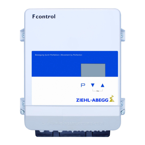
ZIEHL-ABEGG ZETADYN 3BF Manual

Technical Information
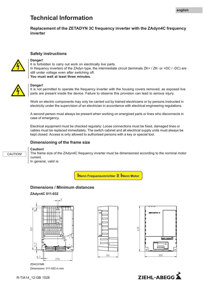
Replacement of the ZETADYN 3BF frequency inverter with the ZAdynpro frequency
inverter
1 General information
1.1 Structure of the operating instructions
These operating instructions are intended to be a short guide with additional information. They are only valid in
conjunction with the following operating instructions:
•R-TBA17_01 (ZAdynpro - part 1)
•R-TBA17_03 (ZAdynpro - part 2)
Before installation and start-up, read this manual carefully to ensure correct use!
2 Safety instructions
Danger!
It is forbidden to carry out work on electrically live parts.
In frequency inverters of the ZAdyn type, the intermediate circuit (terminals ZK+ / ZK- or +DC / -DC) are still
under voltage even after switching off.
You must wait at least three minutes.
Danger!
It is not permitted to operate the frequency inverter with the housing covers removed, as exposed live parts are
present inside the device. Failure to observe this provision can lead to serious injury.
Work on electric components may only be carried out by trained electricians or by persons instructed in
electricity under the supervision of an electrician in accordance with electrical engineering regulations.
A second person must always be present when working on energized parts or lines who disconnects in case
of emergency.
Electrical equipment must be checked regularly: Loose connections must be fixed, damaged lines or cables
must be replaced immediately. The switch cabinet and all electrical supply units must always be kept closed.
Access is only allowed to authorised persons with a key or special tool.
3 Dimensions
ZETADYN 3BF and ZAdynpro have different dimensions. The dimensions of the ZAdynpro and the differences
in dimensions to the ZETADYN 3BF can be found in the table below.
ZAdynpro Height x width x depth Difference to ZETADYN 3BF
Height x width x depth
011 - 017 290 x 150 x 195 -50 x -45 x 10
023 - 032 390 x 151 x 195 50 x -94 x 10
040 517 x 311 x 190 177 x 66 x 5
050 - 074 517 x 311 x 190 17 x -49 x 0
R-TIA19_04-D-GB 2030 Part.-No. 00163470-D-GB
english

4 Saving the parameter values of the ZETADYN 3BF
In order to continue operating the lift with same travel properties, the same parameter settings must
be made on the ZAdynpro as on the ZETADYN 3BF.
There are two ways of ensuring the parameter values:
Noting the parameters of the ZETADYN 3BF
There is a table at the end of this technical information in which you can note the parameter values of
the ZETADYN 3BF. After mechanical and electrical installation, you can set the parameter values on
the ZAdynpro.
Saving the parameters of the ZETADYN 3BF on the memory card
Alternatively, you can save the parameters of the ZETADYN 3BF on the memory card. After mechan-
ical and electrical installation, the parameters can be loaded to the ZAdynpro using the memory card
(see “Parameterisation of the ZAdynpro” chapter).
Procedure for saving the parameters on the memory card
"Insert the memory card in the X-MMC card slot on the controller unit (see figure).
Memory card in the X-MMC card slot
Statistics
->Memory Card
MMC Recorder
Encoder-adjust.
Select "Memory Card" menu
Confirming menu selection
Memory Card
|
-
"SAV_PAR OFF
|
-
"ON
Select "SAV_PAR" parameter
Confirming menu selection
Select "SAV_PAR EIN"
Confirm with the
key.
Please wait ...
Copy1:_ _ _ _ _ _ _
The parameters are saved.
5 Mechanical installation
"Remove all lines connected to the ZETADYN 3BF.
"Remove ZETADYN 3BF.
"Install ZAdynpro. Observe the installation conditions described in the operating instructions of the
ZAdynpro!
Technical Information Saving the parameter values of the ZETADYN 3BF
R-TIA19_04-D-GB 2030 Part.-No. 00163470-D-GB
2/26

6 Electrical installation
6.1 General
Attention!
Parts can be destroyed by electrostatic discharge.
Discharge yourself by suitable action before working on electrical components (connectors, etc.). You can do this,
for example, by touching earthed metal parts.
Refer to the ZAdynpro wiring diagram in this technical information and the ZAdynpro operating
instructions.
6.2 Terminal positions
6.2.1 ZETADYN 3C011 to 3C074
X1
X-EXT
X-BC
X-CO
X-I
X-O
X-BR
X-ENCO
X-CAN / X-AN
X-DCP
X-PAD
X-MMC
X-MT X-ENC8 / X-ENC9 / X-ENC15
Terminal positions
X1 Mains / Motor / Brake-Chopper / Brake-Resistor
X-EXT external 24 V external power supply
X-BC Temperature monitoring of Brake-Chopper / Brake-Resistor
X-CO Contactor monitoring
X-I Digital inputs
X-O Digital outputs
X-MMC Memory card
X-PAD ZETAPAD
X-DCP DCP
X-CAN CAN
X-ENCO Encoder simulation
X-BR Motor brake monitoring
X-ENC8 Encoder
X-ENC9 Encoder SUB-D
X-ENC15 Absolute encoder SUB-D
Technical Information Electrical installation
R-TIA19_04-D-GB 2030 Part.-No. 00163470-D-GB
3/26

6.2.2 ZAdynpro 011-032
1
2
3
4
5
6
7
8
9
Front terminal positions
1 X-MMC memory card
2 X-OUT2 digital outputs
3 X-IN digital inputs
4 X-BC temperature monitoring for brake resistor/brake chopper
5 X-BR inputs for function monitoring of the motor brakes
6 J4 terminating resistance CAN line
7 X-CAN CAN/DCP
8 X-ENC15 rotary encoder SUB-D
9 X-ENCO rotary encoder simulation
1
2
3
4
Position of connection terminals on bottom
1 X3 motor
2 X-STO Safe Torque Off
3 X-SBY standby input
4 X1 line
2
3
1
Terminal positions top
1 X-OUT1 digital outputs
2 X-PAD ZApad
3 X2 brake chopper/brake resistor
Technical Information Electrical installation
R-TIA19_04-D-GB 2030 Part.-No. 00163470-D-GB
4/26

6.2.3 ZAdynpro 040-074
1
2
3
4
5
6
7
8
9
10
11
Front terminal positions
1 X-SBY standby input
2 X-STO Safe Torque Off
3 X-ENCO rotary encoder simulation
4 X-ENC15 rotary encoder SUB-D
5 X-CAN CAN/DCP
6 J1 terminating resistance CAN line
7 X-BR inputs for function monitoring of the motor brakes
8 X-BC temperature monitoring for brake resistor/brake chopper
9 X-IN digital inputs
10 X-OUT2 digital outputs
11 X-MMC memory card
12
34
5
Position of connection terminals on bottom
1 X-OUT1 digital outputs
2 X-PAD ZApad
3 X3 motor
4 X2 brake chopper/brake resistor
5 X1 line
Technical Information Electrical installation
R-TIA19_04-D-GB 2030 Part.-No. 00163470-D-GB
5/26

6.3 Mains connection (X1)
"Remove the FEF mains filter (2) from the mains supply line to the ZETADYN 3BF.
"Connect the connecting cable for the line reactor (3) to connection terminal X1 on the ZAdynpro.
max. 200 mm max. 200 mm
max. 200 mm
1
2
3
4
6
5
7 8
9
10
ZETADYN 3BF
1 Mains supply terminal
2 Radio interference filter FEF
3 Line reactor
4 ZETADYN 3BF
5 Toroidal core for motor cable
6 Motor contactors
7 Brake resistor cable (shielded)
8 Motor cable (shielded)
9 Shielding (brake resistor cable)
10 Clip for contacting the shielding
ZAdynpro
1 ZAdynpro mains connection terminal
2 Power line
3 Motor cable (shielded)
4 Clip for contacting the shielding
5 Route electrical lines with the maximum
possible spacing
6 Line reactor
7 Mains supply terminal
8 Brake resistor cable (shielded)
9 Shielding (brake resistor cable)
ZETADYN 3BF
ZAdynpro
Mains connection (X1) Mains connection (X1)
L1 -> L1
L2 -> L2
L3 -> L3
PE -> PE
Technical Information Electrical installation
R-TIA19_04-D-GB 2030 Part.-No. 00163470-D-GB
6/26

6.4 Motor connection (ZETADYN 3BF: X1, ZAdynpro: X3)
"Remove the motor contactors (6) and toroidal core (5) from the ZETADYN 3BF motor cable.
"Connect the motor cable to connection terminal X2 on the ZAdynpro.
max. 200 mm max. 200 mm
max. 200 mm
1
2
3
4
6
5
7 8
9
10
ZETADYN 3BF
1 Mains supply terminal
2 Radio interference filter FEF
3 Line reactor
4 ZETADYN 3BF
5 Toroidal core for motor cable
6 Motor contactors
7 Brake resistor cable (shielded)
8 Motor cable (shielded)
9 Shielding (brake resistor cable)
10 Clip for contacting the shielding
ZAdynpro
1 ZAdynpro mains connection terminal
2 Power line
3 Motor cable (shielded)
4 Clip for contacting the shielding
5 Route electrical lines with the maximum
possible spacing
6 Line reactor
7 Mains supply terminal
8 Brake resistor cable (shielded)
9 Shielding (brake resistor cable)
•A large area of the screening on the motor cable must be connected to the earth potential in the
immediate vicinity of the ZAdynpro. The screening must continue to the connection terminal as far
as possible.
•We recommend fixing the shielding on the mounting plate by means of a clip (see Fig.).
•The mains supply line and the motor cable must be installed with the maximum possible spacing.
1
Fixing the shielding on the mounting plate
1 Clip
Technical Information Electrical installation
R-TIA19_04-D-GB 2030 Part.-No. 00163470-D-GB
7/26

Please consider the references in the operating instructions of the ZAdynpro for the EMC-
compatible installation.
ZETADYN 3BF
ZAdynpro
Motor connection (X1) Motor connection (X3)
U -> U
V -> V
W -> W
PE -> PE
6.5 Temperature monitoring of the motor (X-MT)
The ZAdynpro has no direct interface for the connection and evaluation of the motor temperature.
There are 2 ways to monitor the motor temperature:
1. Connection of the motor temperature monitoring to the elevator control.
2. Motor temperature monitoring with PTC using the tripping device type U-EK230E
If the elevator control does not provide a direct interface for motor temperature monitoring with PTC,
motor temperature monitoring can be performed using the tripping device type U-EK230E (part no.:
382008). The motor temperature monitoring is connected to the connection terminals (T1) / (T2) on
the tripping unit. The output signals at the connection terminals (11) / (12) / (14) on the tripping device
are connected to any input on the ZAdynpro.
The input must be configured in the Control menu with the parameter 49:MOT_TEMP.
Control
|
-
"f_I08 47:CO
|
-
"49:MOT_TEMP
Function I08
For further information on the tripping device type U-EK230E, refer to the operating instructions L-
BAL-E185-D 1902 Index 004; ZNr. 11660-0710-02.
Tripping device type U-EK230E
1
2
3
Display and control panel
1 Alarm red
2 Power ON green
3 Reset button
X-BR
ZAdynpro
BR3
(2) (5)
+24V_
OUT
Connection suggestion
Technical Information Electrical installation
R-TIA19_04-D-GB 2030 Part.-No. 00163470-D-GB
8/26

6.6 Brake chopper/brake resistor (X-2)
ZETADYN 3C
ZAdyn4C
Brake chopper/brake resistor (X-2) Brake chopper/brake resistor (X-2)
+DC -> +DC
R -> R
PE -> PE
Screen (pigtail) -> Screen (pigtail)
6.7 Temperature monitoring brake chopper/brake resistor (ZETADYN 3BF: X-BC,
ZAdynpro: X-BC)
ZETADYN 3BF
ZAdynpro
Temperature monitoring brake chop-
per/brake resistor (X-BC)
Temperature monitoring brake chop-
per/brake resistor (X-BC)
+24 V (2) -> +24 V (1)
BC (3) -> BC (2)
PE (4) -> PE (3)
Connection terminal X-BC ZETADYN 3BF
Connection terminal X-BC ZAdynpro 011-032
Connection terminal X-BC ZAdynpro 040-074
Technical Information Electrical installation
R-TIA19_04-D-GB 2030 Part.-No. 00163470-D-GB
9/26

6.8 Digital inputs (X-IN)
The connection assignment is identical on both ZETADYN 3BF and ZAdynpro. The connecting lead
can be reconnected directly from the ZETADYN 3BF to the ZAdynpro. The connector on the ZAdynpro
must then be removed.
ZETADYN 3C
ZAdyn4C
Digital inputs (X-I) Digital inputs (X-IN)
+24V (1) -> +24V (1)
+24V_IN (2) -> +24V_IN (2)
I01 (3) -> I01 (3)
I02 (4) -> I02 (4)
I03 (5) -> I03 (5)
I04 (6) -> I04 (6)
I05 (7) -> I05 (7)
I06 (8) -> I06 (8)
I07 (9) -> I07 (9)
I08 (10) -> I08 (10)
GND_IN (11) -> GND_IN (11)
GND (12) -> GND (12)
Shielding (13) -> Shielding (13)
Connection terminal X-I ZETADYN 3BF
Connection terminal X-IN ZAdynpro 011-032
Connection terminal X-IN ZAdynpro 040-074
Technical Information Electrical installation
R-TIA19_04-D-GB 2030 Part.-No. 00163470-D-GB
10/26

6.9 Digital outputs (X-OUT)
CAUTION!
Attention!
Observe minimum and maximum switching capacity.
X-OUT1 X-OUT2
Min. switching ca-
pacity
5 mA / 12 VDC 5 mA / 12 VDC
Max. switching ca-
pacity
2 A/250 VAC 500 mA/24 VDC
ZETADYN 3BF
ZAdynpro
Digital outputs (X-OUT) Digital outputs (X-OUT1, X-OUT2)
O11/O14 (1), (2) -> O11/O14 X-OUT1 (1), (2)
O21/O24 (4), (5) -> O21/O24 X-OUT1 (3), (4)
O31/O34 (7), (8) -> O31/O34 X-OUT1 (5), (6)
O41/O44 (10), (11) -> O41/O44 X-OUT2 (1), (2)
O51/O54 X-OUT2 (3), (4)
Connection terminal X-OUT ZETADYN
3C
Connection terminal X-OUT1
ZAdynpro 011-032
Connection terminal X-OUT2
ZAdynpro 011-032
Connection terminal X-OUT1
ZAdynpro 040-074
Connection terminal X-OUT2
ZAdynpro 011-032
Technical Information Electrical installation
R-TIA19_04-D-GB 2030 Part.-No. 00163470-D-GB
11/26

6.10 Pulse generator for asynchronous motors (ZETADYN 3BF: X-ENC8, ZAdynpro: X-
ENC15)
•Only TTL sinus encoders or incremental encoders are to be connected. HTL encoders may not be
connected. If an HTL encoder has been used on the ZETADYN 3BF it must be replaced with TTL
sinus or TTL rectangular encoder.
•When connecting the encoder line to connection terminal X-ENC15 on the ZAdynpro, the "Adhe-
sion spring connection adaptor connector <-> D - SUB 15" (article number: 00152676) is to be
used.
•The single cores must be connected to the adaptor connector as set out in the table.
ZETADYN 3BF
ZAdynpro
Encoder connection asynchronous mo-
tors (X-ENC8)
Encoder connection asynchronous mo-
tors (X-ENC15)
A (A) -> A (12)
/A (/A) -> /A (13)
B (B) -> B (7)
/B (/B) -> /B (14)
+5/8V_E (5V) -> 5V_E (4)
GND (GND) -> GND (5)
-> (housing)
Connection terminal X-ENC8 ZETADYN 3BF
(TTL or sinus encoder)
Adaptor connector connection terminals
Connection terminal X-ENC15 ZAdynpro (TTL or sinus
encoder)
Technical Information Electrical installation
R-TIA19_04-D-GB 2030 Part.-No. 00163470-D-GB
12/26

6.11 Pulse generator for asynchronous motors (ZETADYN 3BF: X-ENC9, ZAdynpro: X-
ENC15)
Use the "adapter D - SUB 9 <-> D - SUB 15" when connecting the encoder cable to the connection
terminal X-ENC15 of the ZAdyn4C.
Type designation of the adapter: L-GL-004-HX-ZA-ASM-9-15
Article no. of the adapter: 00165930-004M
ZETADYN 3BF
ZAdynpro
Encoder connection asynchronous mo-
tors (X-ENC9)
Encoder connection asynchronous mo-
tors (X-ENC15)
SUB-D 9-pole -> SUB-D 15-pole
Connection terminal X-ENC9 ZETADYN 3BF
Connection terminal X-ENC15 ZAdynpro 011-032
Connection terminal X-ENC15 ZAdynpro 040-074
Technical Information Electrical installation
R-TIA19_04-D-GB 2030 Part.-No. 00163470-D-GB
13/26

6.12 Encoder connection synchronous motors (X-ENC15)
Attention!
If a type ERN 1387 absolute value encoder is used, the present encoder cable must be replaced with
the encoder cable L-GL-10-YY-ZA4-ERN1387 (article no. 00165948-10M).
The connection assignment is identical on both the ZETADYN 3BF and the ZAdynpro. The connecting
cable can be reconnected directly from the ZETADYN 3BF to the ZAdynpro.
ZETADYN 3BF
ZAdynpro
Encoder connection synchronous mo-
tors (X-ENC15)
Encoder connection synchronous mo-
tors (X-ENC15)
SUB-D 15-pole -> SUB-D 15-pole
Connection terminal X-ENC15 ZETADYN 3BF
Connection terminal X-ENC15 ZAdynpro 011-032
Connection terminal X-ENC15 ZAdynpro 040-074
Technical Information Electrical installation
R-TIA19_04-D-GB 2030 Part.-No. 00163470-D-GB
14/26

6.13 DCP interface (ZETADYN 3BF: X-DCP, ZAdynpro: X-CAN)
ZETADYN 3BF
ZAdynpro
DCP-interface (X-DCP) DCP interface (X-CAN)
DA (1) -> DCP_A (4)
DB (2) -> DCP_B (2)
0VD (3) -> GND_COM (1)
(4) -> (3)
Connection terminal X-DCP ZETADYN 3C
Connection terminal X-ENC15 ZAdynpro 011-032
Connection terminal X-CAN (DCP) ZAdynpro 040-074
Technical Information Electrical installation
R-TIA19_04-D-GB 2030 Part.-No. 00163470-D-GB
15/26

6.14 CAN interface (X-CAN)
The connection assignment is identical on both the ZETADYN 3BF and the ZAdynpro. The connecting
cable can be reconnected directly from the ZETADYN 3BF to the ZAdynpro.
ZETADYN 3BF
ZAdynpro
CAN interface (X-CAN) CAN interface (X-CAN)
CH (4) -> CH (4)
(3) -> (3)
CL (2) -> CL (2)
0VC (1) -> 0VC (1)
Connection terminal X-CAN ZETADYN
3BF
Connection terminal X-CAN
ZAdynpro 011-032 Connection terminal X-CAN
ZAdynpro 040-074
To activate the terminating resistor, the jumper at terminal J4
(ZAdynpro 011-032) or J1 (ZAdynpro 040-074) must be con-
nected to the two right pins (see Fig.).
Jumper on the left two pins
Technical Information Electrical installation
R-TIA19_04-D-GB 2030 Part.-No. 00163470-D-GB
16/26

6.15 Encoder simulation (X-ENCO)
ZETADYN 3BF
ZAdynpro
Encoder simulation (X-ENCO) Encoder simulation (X-ENCO)
X (6) -> X (4)
/X (5) -> /X (3)
Y (4) -> Y (2)
/Y (3) -> /Y (1)
GND (2) -> - -
(1) -> 1) -
1)
The screening of the cable must be connected on the control side.
Connection terminal X-ENCO ZETADYN 3BF
Connection terminal X-ENCO ZAdynpro 011-032
Connection terminal X-ENCO ZAdynpro 040-074
Technical Information Electrical installation
R-TIA19_04-D-GB 2030 Part.-No. 00163470-D-GB
17/26

6.16 Brake bleed monitor (X-BR)
ZETADYN 3BF
ZAdynpro
Brake bleed monitor (X-BR) Brake bleed monitor (X-BR)
+24V_B (6) -> +24V_OUT (5)
BR1 (5) -> BR1 (4)
BR2 (4) -> BR2 (3)
BR3 (3) -> BR3 (2)
BR4 (2) -> - -
(1) -> - -
Connection terminal X-BR ZETADYN 3BF
Connection terminal X-BR ZAdynpro 011-032
Connection terminal X-BR ZAdynpro 040-074
Technical Information Electrical installation
R-TIA19_04-D-GB 2030 Part.-No. 00163470-D-GB
18/26

7 Function "Safe Torque Off (STO)" of the ZAdynpro
7.1 General
The motor contactors are replaced by the STO function in the ZAdynpro. The STO function is
activated by two safety-related inputs at the interface X-STO. Both inputs must be activated via two
separate relays whose control voltage is supplied at the end of the electrical safety chain.
Please consider the references in the operating instructions of the ZAdynpro when using the "Safe
Torque Off (STO)" function.
A monitoring by the control of the both relais for switching the STO inputs is not necessary if the
connection is carried out according to the operating instructions of the ZAdynpro. The monitoring of
the relais is ensured by the internal diagnostic unit of the ZAdynpro.The state of the function STO can
be requested optionally (not safety-related) via a digital input with the function "STO-Info"or "/STO-
Info".
If the state is requested via a digital output, the digital output has to be configured in the control
system menu to STO-Info or /STO-Info.
Control
|
-
"f_O5 STO_Info
|
-
"STO_Info
Function O5
8 Configuration of the ZAdynpro
There are two processes for configuring the ZAdynpro:
Manual configuration
Use the parameter settings noted in the table in the appendix for the ZAdynpro.
Loading parameters onto the ZAdynpro
Alternatively, you can load the parameters for the ZETADYN 3BF onto the ZAdynpro using a memory
card.
Procedure for loading parameters onto the ZAdynpro
"Insert the memory card in the X-MMC card slot (see figures).
Memory card in the X-MMC card slot of ZAdynpro
011-032 Memory card in card slot X-MMC on ZAdynpro 040-074
Statistics
->Memory Card
MMC Recorder
Encoder-adjust.
Select "Memory Card" menu
Confirming menu selection
Technical Information Function "Safe Torque Off (STO)" of the ZAdynpro
R-TIA19_04-D-GB 2030 Part.-No. 00163470-D-GB
19/26

Memory Card
|
-
"LOD_PAR 0
|
-
"327
Select "LOD_PAR" parameter
Confirming menu selection
Enter "LOD_PAR 327"
Confirm with the
key.
Please wait ...
Copy1:_ _ _ _ _ _ _
The parameters are loaded.
Technical Information Configuration of the ZAdynpro
R-TIA19_04-D-GB 2030 Part.-No. 00163470-D-GB
20/26
Other manuals for ZETADYN 3BF
1
Table of contents
Other ZIEHL-ABEGG Inverter manuals
Popular Inverter manuals by other brands

Micno
Micno 3kW DC24V user manual

LSIS
LSIS SV-iS7 series user manual

SolaX Power
SolaX Power X3-Retro Fit Series Quick installation guide

Growatt
Growatt SPF 5000 ES user manual

Aybey Elektronik
Aybey Elektronik AE-LIFT Series user manual

Zeversolar
Zeversolar Zeverlution 3680 Installation and operating instructions

Omega
Omega OTEC IEWH Series Service manual

SAJ
SAJ Suntrio-TL8K user manual

Victron energy
Victron energy MultiPlus 12 1600 70 230V manual

Mule Lighting
Mule Lighting LPS Series Installation & operation instructions

enphase
enphase M215 Installation and operation manual

Mastervolt
Mastervolt Sunmaster XS4300 User and installation manual