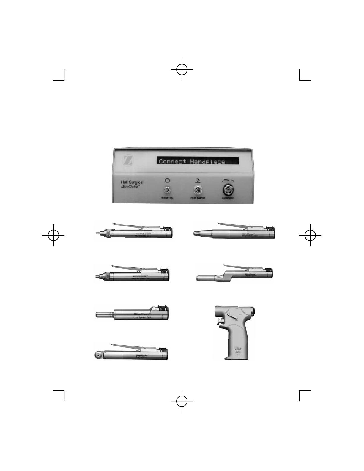
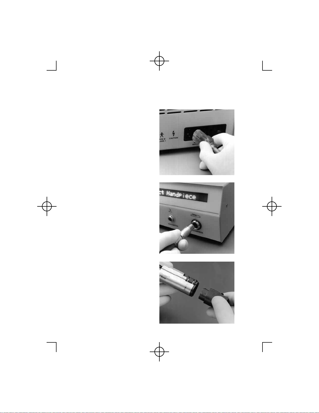
Zimmer Hall MicroChoice System User manual

The Hall
®
MicroChoice
™
System
Instruction Manual


1
Table of Contents Page
General Warnings. . . . . . . . . . . . . . . . . . . . . . . . . . . . . . . . . . . . . . . . . . 2
MicroChoice
™ Controller . . . . . . . . . . . . . . . . . . . . . . . . . . . . . . . . . . . 4
General Handpiece Instructions. . . . . . . . . . . . . . . . . . . . . . . . . . . . . . . 8
MicroChoice
High Speed Drill . . . . . . . . . . . . . . . . . . . . . . . . . . . . . . 11
MicroChoice
Medium Speed Drill. . . . . . . . . . . . . . . . . . . . . . . . . . . . 13
MicroChoice
Drill Attachments/Accessories. . . . . . . . . . . . . . . . . . . . 15
MicroChoice
Low Speed Drill . . . . . . . . . . . . . . . . . . . . . . . . . . . . . . . 20
MicroChoice
Reciprocating Saw . . . . . . . . . . . . . . . . . . . . . . . . . . . . . 23
MicroChoice
Sagittal Saw . . . . . . . . . . . . . . . . . . . . . . . . . . . . . . . . . . 25
MicroChoice
Oscillating Saw . . . . . . . . . . . . . . . . . . . . . . . . . . . . . . . 27
MicroChoice
Wiredriver/Fixation Drill . . . . . . . . . . . . . . . . . . . . . . . . 29
Micro E
®
Handpiece Operation. . . . . . . . . . . . . . . . . . . . . . . . . . . . . . 37
Handpiece Mode Selection . . . . . . . . . . . . . . . . . . . . . . . . . . . . . . . . . 38
Leverless Operation . . . . . . . . . . . . . . . . . . . . . . . . . . . . . . . . . . . . . . . 47
Footswitch Operation. . . . . . . . . . . . . . . . . . . . . . . . . . . . . . . . . . . . . . 49
Irrigation. . . . . . . . . . . . . . . . . . . . . . . . . . . . . . . . . . . . . . . . . . . . . . . . 50
Controller Stand. . . . . . . . . . . . . . . . . . . . . . . . . . . . . . . . . . . . . . . . . . 52
Care and Cleaning Instructions . . . . . . . . . . . . . . . . . . . . . . . . . . . . . . 53
Sterilization Recommendations . . . . . . . . . . . . . . . . . . . . . . . . . . . . . . 56
Hall
®
Surgical Instrument Warranty . . . . . . . . . . . . . . . . . . . . . . . . . . 59
Technical Specifications. . . . . . . . . . . . . . . . . . . . . . . . . . . . . . . . . . . . 61
Calibration . . . . . . . . . . . . . . . . . . . . . . . . . . . . . . . . . . . . . . . . . . . . . . 63
Receiving/Periodic Inspection . . . . . . . . . . . . . . . . . . . . . . . . . . . . . . . 64
Handpiece, Accessories and Attachments . . . . . . . . . . . . . . . . . . . . . . 67

2
GENERAL WARNINGS
1. Prior to each use, all handpieces and accessories must be inspected for
proper operation.
2. The surgeon and all others in the area must always wear eye protection
when operating any Hall
®
Surgical equipment. Eye injury or blindness
can result from dislodged drill bits, blades or bone/tooth fragments.
3. To assure safety of the patient and operating room personnel, use only
Hall Surgical accessories and attachments.
4. Handle all medical instruments carefully. If a Hall device is dropped,
immersed or damaged in any way, it should be returned immediately for
service.
5. Do not attempt to service or open the
MicroChoice
™ Controller. There
are no user serviceable parts inside. If the system malfunctions, return it
to Hall Surgical for service.
6. Put the handpiece in the "safe" position before changing any
accessories, burs or blades.Accidental activation could injure the patient
or operating room personnel.
7. Before each use, be sure accessories are correctly attached to the
handpiece as they could be thrown from the handpiece with great force,
possibly causing serious injury.
8. Always inspect for bent or otherwise damaged burs/blades before each
use. A bent blade or bur can whip severely and could be propelled with
great force, causing injury. Do not use excessive force on any bur or
blade. Do not attempt to straighten a bent blade or bur.
9. The use of dull burs and blades may cause heat build-up in the
handpiece and the bone. It is recommended that single-use burs and
blades be used or, if the hospital does not want to use single-use burs
and blades, inspections with a magnifying glass of all burs and blades
must be done to check for dull and chipped cutting surfaces.

3
10. Overheating might occur if the handpiece or accessory bearings are
worn or are not kept clean. Continually check all parts of the handpiece
and attachments for overheating. Discontinue use and return the
equipment for service as necessary. Overheating can cause serious
injury to the patient or operating room personnel.
11. Please pay close attention to the "Care and Cleaning Instructions" and
all "Cautions" in the “
MicroChoice
™
System Instruction Manual
”.
12. Never immerse the
MicroChoice
Controller, Footswitch or handpieces
in any solution.
13. Do not lubricate any
MicroChoice
handpiece.
14. Hall
®
Surgical equipment is designed for use by medical professionals
who are completely familiar with the required surgical techniques and
instructions for use of the equipment.
15. Do not autoclave the
MicroChoice
Controller.
16. Always inspect cords for signs of excessive wear or damage.
Discontinue use and replace immediately or return for repair.
17. Never lock the collet on the High Speed or Medium Speed Drills
without a bur in place, or damage to the collet may result.
18. Do not pick up
MicroChoice
handpieces or the Footswitch by the cord.
Damage to the connection or cord may result.
19. Do not press the Mode button on the Handpiece Cord until a handpiece
is attached.

4
MICROCHOICE
™
CONTROLLER
The Hall
®
MicroChoice
Controller is designed and manufactured
specifically to power only
MicroChoice
and levered Micro E
®
handpieces.
The
MicroChoice
Controller is designed to operate on grounded electrical
power.
Important Note: The Controller will not detect improper grounding
between itself and the electrical outlet. Proper procedures must be
followed to assure proper grounding of the Controller.
The system is designed to meet standard electrical safety requirements for
surgical instruments that are likely to be applied to a patient in a health care
facility.
Notes: The
MicroChoice
Controller is designed with "closed loop
feedback". This design provides immediate electronic feedback to hold
handpiece speed constant even with increasing load. Caution should be
exercised while becoming familiar with the operation of the
MicroChoice
system.
Each
MicroChoice
Controller is shipped from the factory pre-set to your
power requirements. See page 61, Technical Specifications, for
information regarding fuses and selecting voltage options.
PRIOR TO PUTTING THE SYSTEM INTO USE, REFER TO THE
“RECEIVING/PERIODIC INSPECTION” SECTION ON PAGE 64
FOR IMPORTANT INFORMATION

5
Symbol Definitions:
Power "OFF"
Power "ON"
Attention, consult accompanying documents
Handpiece Connection
Footswitch Connection
Irrigation Pump Connection
Type B, Class 1 Equipment
Caution
Flammable Anesthetics - Risk of explosion if used in the
presence of flammable anesthetics.

6
To Activate
MicroChoice
™
Controller:
1. Plug the power cord into the
receptacle on the rear of
Controller. Plug remaining end of
power cord into a standard
grounded wall outlet. Once the
power cord has been connected,
no front panel lights should be
activated. If the display panel is
activated, depress the Power On/
Off switch to deactivate the
system.
2. Align the red indicator dot on the
Handpiece Cord connector with
the matching dot above the
Handpiece receptacle. Push the
connector into the Handpiece
receptacle. The receptacle and
cord connector are color coded
(red) and keyed so the cord cannot
be improperly attached. Care must
be exercised so as not to bend or
break the contact pins within the
Controller receptacle.
3. Attach the Handpiece Cord to the
desired handpiece. (See General
Handpiece Instructions, starting
on page 8.) The Handpiece Cord
and handpiece connection area are
keyed so the connection is simple
and unique. Care should be taken
so as not to bend or break the
connector pins within the
Handpiece.

7
4(a) Once the chosen handpiece has
been attached, activate the system
by depressing the On/Off power
switch on the back of the
Controller. When the power
switch has been depressed, the
display panel will display with
HALL SURGICAL
. The
Controller will go through a self-
diagnostic check indicating the
software version. At the
conclusion of the check, the
attached handpiece I.D. and speed
will be displayed followed by
SETTING DONE!!!
. Lastly
displayed is the handpiece I.D.
and
SAFE ON
. The system is
activated and ready for use.
Detailed instructions regarding
operation of the
MicroChoice
™
Controller and handpieces can be
found on pages 38 - 47,
Handpiece Mode Selections.
(b) With the power on, the Handpiece Cord may be disconnected from one
handpiece and installed on another handpiece. (When power is "ON"
and the Handpiece Cord is removed from one handpiece, power is
disconnected within the Handpiece Cord). When a second handpiece is
connected to the Handpiece Cord, power is restored to the Handpiece
Cord. The Controller will display the I.D. of the second handpiece with
SAFE ON
.

8
(c) Operation of the handpiece can
begin by moving the Safe/Run
Slide to the "run" position. Each
handpiece will initially operate at
its default setting. Desired settings
can be stored in memory by
following the instructions outlined
in the Handpiece Mode Selection
section (See Handpiece Mode
Selection, pages 38 - 47, for
default settings and "Day-to-Day"
memory setting instructions).
GENERAL HANDPIECE INSTRUCTIONS
With the exception of the Pencil Grip Wiredriver and Wiredriver/Fixation
Drill, all
MicroChoice
handpieces have the same basic configuration and
many features in common. (See pages 29 - 36, Wiredriver/Fixation Drill.)
1. To prevent accidental activation of
the handpiece, always keep the
"safe/run" Slide on the handpiece
in the back or "safe" position. The
word "safe" on the handpiece
barrel is visible through the
opening on the Safety Slide.
2. To attach the handpiece to the
Handpiece Cord:
(a) Place the handpiece in the "safe"
position.

9
(b) Firmly grasp both the connection
end of the handpiece and the
connector end of the Handpiece
Cord.
(c) The Handpiece Cord connector
has been designed in a fashion
where attachment can only occur
in one orientation. Improper
attachment of the cord is not
possible.
(d) Align the mechanical "spring
lock" mechanism portion of the
Handpiece Cord with the top of
the handpiece.
(e) Once the cord connector and the
handpiece receptacle are properly
aligned, push together until the
cord connector is fully seated in
the handpiece. The Controller will
identify the handpiece I.D.
connected and display
SAFE ON
.

10
3. To activate the handpiece, move
the Safe/Run Slide forward. "Run"
will be visible through the
opening. The Controller will
display the connected handpiece
I.D. along with the maximum
RPM or speed setting.
4. Without any user input selections
(see Handpiece Mode Selection
instructions for available settings)
the Controller will display the
default setting and the handpiece
will operate within this range. (For
an explanation of default settings
and other available options, see
the Operating Instructions of the
connected handpiece.) The
handpiece is now ready for
operation. Depress the Activation
Lever or Footswitch to activate.
Note 1: If a
MicroChoice
™ handpiece is placed on a magnetic drape,
the Controller may display MAGNETIC FIELD. The handpiece will be
inoperable until the magnet and handpiece are separated. Once
separated, the Controller will reset after three (3) seconds.
Note 2: Handpieces are inoperable if the Activation Lever or
Footswitch are depressed while the connection to the Handpiece Cord is
made.
Note 3: Operation of a
MicroChoice
drill without a bur in place is
considered a failure mode. When the handpiece is activated for several
seconds the Controller will display STALL CHECK BUR LOCK.
Operation can not be initiated until a bur is locked in place and at least
five (5) seconds have elapsed without either the Footswitch orActivation
Lever depressed.

11
HIGH SPEED DRILL
Specifications:
Operating Speed 100,000 rpm Maximum
Maximum Speed Settings 10,000 to 100,000 rpm in 10,000
rpm increments
Torque 2 in. oz.
Bur Pull Out Force Exceeds 12.0 lbs. (5.4 kg.)
Warning: Place Safe/Run Slide in the "safe" position when not in use.
Always operate the High Speed Drill with the appropriate bur guard or
attachment. Use a bur of the appropriate length - the tip of the bur guard
should cover the safe line on the bur. Without the stabilization that the proper
guard provides, the bur can break and be propelled with great force.
Check each bur before use in the High Speed Drill. Never use a bent bur. For
additional information, refer to the
MicroChoice
™ Bur Guard Package
Insert, or contact Hall
®
Surgical.
Activation Lever Safe/Run Slide
Twist Bur Lock

12
1. To insert a bur, slide the
appropriate bur guard over the
end of the High Speed Drill.
Be certain it is completely
seated.
2. Twist the bur lock to the
"Open" position. Insert the bur
to the safe line or until the bur
seats completely.
3. To secure the bur, twist the bur
lock until the red indicator
dots are aligned in the "Lock"
position.
Warning: Before each use be sure that burs are completely seated and
locked in the handpiece.

13
MEDIUM SPEED DRILL
Specifications:
Operating Speed 25,000 rpm Maximum
Maximum Speed Settings 1,000 to 25,000 rpm in 2,000
rpm increments
Torque 6 in. oz.
Bur Pull Out Force Exceeds 12.0 lbs. (5.4 kg.)
Warning: Place Safe/Run Slide in the "safe" position when not in use.
Always operate the Medium Speed Drill with the appropriate bur guard or
attachment. Use a bur of the appropriate length - the tip of the bur guard
should cover the safe line on the bur. Without the stabilization that the proper
guard provides, the bur can break and be propelled with great force.
Check each bur before use in the Medium Speed Drill. Never use a bent bur.
For additional information, refer to the
MicroChoice
™ Bur Guard Package
Insert, or contact Hall
®
Surgical.
Activation Lever Safe/Run Slide
Twist Bur Lock

14
1. To insert a bur, slide the
appropriate bur guard over the
end of the Medium Speed
Drill. Be certain it is
completely seated.
2. Twist the bur lock to the
"Open" position and insert the
bur to the safe line or until the
bur seats completely.
3. To secure the bur, twist the bur
lock until the red indicator
dots are aligned in the "Lock"
position.
Warning: Before each use be sure
that burs are completely seated
and locked in the handpiece.

15
DRILL ATTACHMENTS AND ACCESSORIES
MicroChoice
™ High Speed and Medium Speed Drills
Warning: Place handpiece in the "safe" position prior to connection
with the attachment. Be certain the attachment/accessory is completely
seated on the handpiece prior to each use.
To use the
MicroChoice
Drill Attachments/Accessories:
Open the handpiece collet to
the "Open" position by
twisting the bur lock to the left
(counterclockwise).
Seat the attachment/accessory
completely over the end of the
Drill.
To lock the attachment/
accessory into place, twist the
bur lock (clockwise) until the
red indicator dots are aligned.

16
20
°
and Extra-Long 20
°
Angle Attachments:
Caution: Use only Hall
®
long 5092 burs with the 20
°
AngleAttachment
and only Hall extra-long 5093 burs with the Extra-Long 20
°
Attachment.
Twist the bur lock on the
attachment to the "Open"
position.
Insert the bur to the safe line or
until the bur seats completely.
Twist the bur lock until the
indicator dots are aligned in
the "Lock" position.

17
70
°
Surgical Head and 90
°
Angle Attachments:
Caution: Use only Hall
®
short 5090 and extra-short 5089 series burs
with the 70
°
Contra-Angle Attachment and the 90
°
Angle Attachment.
Place the bur in the opening on
the attachment.
Use the grooved side of the bur
changer (1375-003) to press
the bur firmly in place.
To remove the bur: Place the
bur changer in the opening at
the rear of the attachment.
Press firmly on the bur
changer to push the bur out.

18
70
°
Dental Head
The 70
°
Dental Head attachment uses friction grip burs only - size 1/16"
or 1.58 mm in diameter. Friction grip burs are not marketed by Zimmer.
They are available through dental supply dealers.
Tissue Retractor Bur Guard:
Slide the guard over the end of
the drill so it is completely
seated.
Open the handpiece collet to
the "Open" position by
twisting the bur lock to the left
(counterclockwise).
Insert the bur (any 5092 series
bur with a head diameter of
4mm or less) through the tip of
the bur guard and into the
handpiece collet. The
recommended bur is 5092-
136, Long Oval Cutting Bur.
Twist the bur lock (clockwise)
until the red indicator dots are
aligned to lock the bur into
place.
Table of contents
Other Zimmer Medical Equipment manuals

Zimmer
Zimmer MicroPro User manual

Zimmer
Zimmer enPuls User manual

Zimmer
Zimmer Soleo SonoStim User manual

Zimmer
Zimmer PremoPortFour User manual

Zimmer
Zimmer enPuls User manual

Zimmer
Zimmer CryoMini User manual

Zimmer
Zimmer Cryo 6 User manual

Zimmer
Zimmer Gentle Pro User manual

Zimmer
Zimmer MIS Multi-Reference User manual

Zimmer
Zimmer Persona User manual

Zimmer
Zimmer enShock User manual

Zimmer
Zimmer Cryo 6 User manual

Zimmer
Zimmer emFieldPro User manual

Zimmer
Zimmer enPulsPro User manual

Zimmer
Zimmer Sono One User manual

Zimmer
Zimmer Z Wave Med User manual

Zimmer
Zimmer A.T.S. 4000TS User manual

Zimmer
Zimmer A.T.S. 1200 User manual

Zimmer
Zimmer Meshgraft II User manual

Zimmer
Zimmer Opton User manual