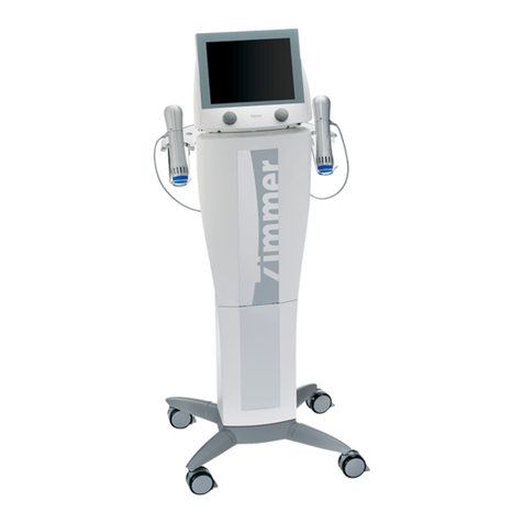
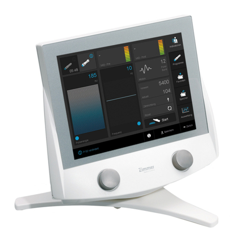
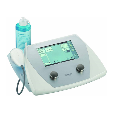
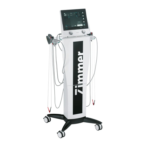
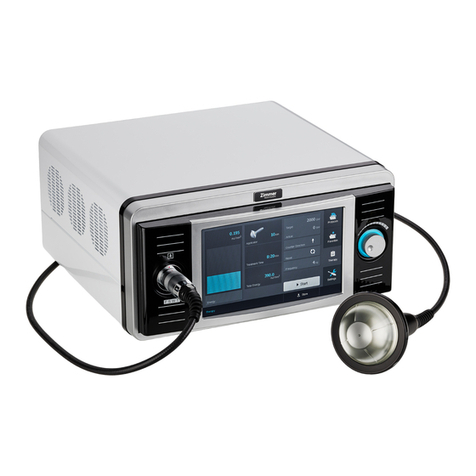
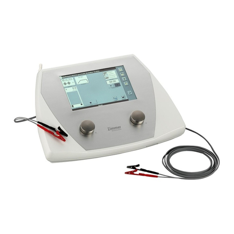
Zimmer SD Edition PhySys User manual


PhySys Edition SD Service Manual Rev. B
20.08.2013
Page 2/52
Service Manual PhySysSD_RevB_20.08.2013.do
c
Document history
Rev. Date Change Originator
A 01.02.2011 Initial Release R. Alareki
B 20.08.2013 Correction layout / device name,
incorporation description software update F. Bechtold

PhySys Edition SD Service Manual Rev. B
20.08.2013
Page 3/52
Service Manual PhySysSD_RevB_20.08.2013.do
c
Table of content
1.Safety Instructions 5
2.Returning a device 6
2.1.Packaging 6
3.Repairing Printed Circuit Boards 6
4.Special incidents 6
5.Device general description 7
5.1.Over view 7
6.Electronic 9
6.1.Overview 9
6.1.1.Electronic description of the PhySys Edition SD device 9
6.1.2.Electronic description of the VacoP device 14
6.2.Pin Assignments 16
6.2.1.Overview PhySys Edition SD device 16
6.2.2.Overview Vaco device 17
6.2.2.1.VacoP User connection 17
6.2.2.2.Power supply connection (ST1001) 17
6.2.2.3.Jumper (JP1001-JP1004) 17
6.2.2.4.VacoP User connection (ST1201) 17
6.2.2.5.Stimulating current connection (ST1204) (PhySys Edition SD/ Vacoboard) 17
6.2.2.6.Stimulating current connection (ST1203) (VacoP mainboard/ suction electrodes) 18
6.2.2.7.Pump connection (BU1401) 18
6.2.2.8.Valve connection (ST1502) 18
6.2.2.9.Water level sensor connection (ST1202) 18
7.Software 19
7.1.Installation programme update 19
7.1.1.Necessary tools 19
7.1.2.Download and Installation of the SD-card-update program 19
7.2.Processing the SD-card update 23
7.3.Update the PhySys Edition SD 25
8.Mechanic 28
8.1.General Overview 28
8.1.1.Device Structure of the PhySys Edition SD 28
8.1.2.Device Structure of the Vaco device 30
8.2.Accessory List 31
8.3.Replacement of device components 31
8.3.1.Replacement of PhySys Edition SD components 31
8.3.1.1.Opening the rear part of housing 31
8.3.1.2.Mounting the rear part of housing 32
8.3.1.3.Removing of the front part of housing 32
8.3.1.4.Mounting the front part 33
8.3.1.5.Replacement of the speaker 33
8.3.1.6.Replacement of the main board 33
8.3.1.7.Replacement of the Display 34
8.3.1.8.Replacement of the battery 35
8.3.1.9.Replacement of power inlet element 36
8.3.1.10.Replacement of power supply board 37
8.3.2.Replacement of the VacoP components 38
8.3.2.1.Replacement of the water separator 38
8.3.2.2.Replacement of the pump 39
8.3.2.3.Replacement of the vaco board 40

PhySys Edition SD Service Manual Rev. B
20.08.2013
Page 4/52
Service Manual PhySysSD_RevB_20.08.2013.do
c
9.Technical Data 41
10.Troubleshooting 42
10.1.Spare Parts Handling 42
10.2.Required Equipment 42
10.3.Starting Problems 43
10.4.Error Messages 44
10.4.1.General description 44
10.4.2.Master Processor 44
10.4.3.Slave Processor 46
10.4.4.Cable Control Problems 47
10.5.Problems without Error message 48
10.6.Test Run 49
10.6.1.PhySys Edition SD 49
10.6.2.VacoP 49
11.Service report 50
12.Safety check 51
12.1.PhySys Edition SD 51
12.2.VacoP device 52

PhySys Edition SD Service Manual Rev. B
20.08.2013
Page 5/52
Service Manual PhySysSD_RevB_20.08.2013.do
c
1. Safety Instructions
Zimmer MedizinSysteme GmbH as the manufacturer of electro medical devices can only accept liability for the safety
and reliability of the device under the following conditions:
xThe electrical installation conforms to the requirements specified for operation of the device
xThe device is operated as specified by the user manual
xExtensions, new settings or changes are only carried out by persons authorized by Zimmer MedizinSysteme
Zimmer MedizinSysteme reserves the right to make changes to delivery options and technical features. Contract service
partners are responsible for all repairs that they conduct.
Screws that must be removed to open the housing are protected by a special warranty seal. Only authorized persons are
permitted to remove them. If the seal is missing or has been manipulated, the device will no longer be under warranty.
The information in the service documentation is the property of the manufacturer and intended for internal use by our
technicians only. Publication of this information or distribution to unauthorized persons is prohibited. If the service
contract is canceled, the technician(s) is/are required returning the service documentation to Zimmer MedizinSysteme
GmbH.
Warning!
Unauthorized modifications or repairs to the device may cause it to malfunction and cause serious injuries.

PhySys Edition SD Service Manual Rev. B
20.08.2013
Page 6/52
Service Manual PhySysSD_RevB_20.08.2013.do
c
2. Returning a device
2.1. Packaging
Every unit that is sent to the manufacturer for service must be packed in the original packaging to prevent any
damage during shipping. Always include a detailed description of any faults; please use the service report in
(chapter11).
3. Repairing Printed Circuit Boards
Faulty boards must be repaired by the manufacturer only. After replacing a module, the faulty part must be labelled with
the serial number of the device and returned to the manufacturer with the service report in (chapter 11).
4. Special incidents
Zimmer MedizinSysteme is required to record malfunctions and incidents of any type. Please report all unusual incidents
(e.g. electric shock, burns etc.) Please use the service report included with the documentation (chapter 11). Your reports
will contribute to improving the quality and reliability of our products.

PhySys Edition SD Service Manual Rev. B
20.08.2013
Page 7/52
Service Manual PhySysSD_RevB_20.08.2013.do
c
5. Device general description
5.1. Over view
The therapy device PhySys Edition SD includes stimulation current therapy and ultrasonic therapy with the possibility to
combine it with the VacoP device to suction-wave massage.
The stimulation current module is used for stimulation current therapy and -diagnostics according to the standard
medical practices also in combination with the internal ultrasonic module (simultaneous procedure). The ultrasonic
module is used for ultrasonic therapy according to the standard medical practices. The suction-wave module is used for
suction-wave therapy and in combination with the stimulation current module is also used for positioning the suction
electrodes.
The device has a plastic housing. The power Inlet element with 2x implemented mains fuses, the connection sockets for
the patient cables and ultrasonic heads and an Ethernet connection are all placed at the rear side of the housing. The
power switch is located at the right side of the lower part of housing.
The adjusting Knobs to set the output intensity are placed at the front part of the housing.
The device is operated by 2 actuators (adjusting knobs) and a touch screen. All device functions are controlled by a
microprocessor.
The device contains 2 galvanically separated stimulation current modules, where the ultrasonic module is also integrated
in one of those modules for therapy in the simultaneous procedure mode.
The ultrasonic component generates the necessary signals for transmitting the selected acoustic power to the patient via
a transducer.
The suction-wave component is located in the VacoP device and can only be operated by the microprocessor located in
the PhySys Edition SD.
The communication between PhySys Edition SD and the VacoP device is realised by connecting cables. All needed
signals and values for the VacoP operating are controlled and generated by the PhySys Edition SD device. Further all
safety relevant procedure of the suction- wave operating are implemented and monitored by the PhySys Edition SD
device.
Front view
Figure 1: Front view of the PhySys Edition SD device
Slot for SD-
Card Main switch

PhySys Edition SD Service Manual Rev. B
20.08.2013
Page 8/52
Service Manual PhySysSD_RevB_20.08.2013.do
c
Figure 2: Right view of PhySys Edition SD Figure 3: Left view of PhySys Edition SD
Figure 4: Front view of VacoP device
Figure 5:Rear view of the VacoP device
Channel 2
Channel 1
Ethernet
connection
Ultrasonic
connection
Stimulating current
connection
Housing
Water
separator
Pump
PCB

PhySys Edition SD Service Manual Rev. B
20.08.2013
Page 9/52
Service Manual PhySysSD_RevB_20.08.2013.do
c
6. Electronic
6.1. Overview
6.1.1. Electronic description of the PhySys Edition SD device
The whole electronic hardware of the PhySys Edition SD is placed on 2x boards.
The first board (mainboard) contains the power supply for the processor and DSPs, the periphery operating section for
the graphical- and acoustic signals, for the touch controller, components for operating the actuators, the stimulation
current signal generation components and the ultrasonic generation components. Further the electrical circuits for the
monitoring of the stimulating currents and voltages and relays for switching of the setting channels are also integrated on
this board.
The second board is the power supply board, which contains a wide-range switching power supply unit for a voltage
range between (90V to 275V). All device external connectors for the stimulating currents and ultrasonic therapy are also
located on this board. Several connecting cables realize the communication between these two boards.
The next figures show the various circuit sections and components on the main board.
Figure 6: Top view of the mainboard
PCB-block to generate
and regulate the patient
stimulating current and
ultrasonic for channel 2
CPU
Touch screen
connection
Battery
PCB-block to
generate and regulate
the patient stimulating
current for channel 1
EEPROM
Real Time Clock
Backlight
connection
JTAG
(Debug CPU)
Watchdog
jumper
Audio connection
User Vaco
connection
User
Display
connection
User Control Connection
Connection for
actuator board
User PC 1
(Stimulating current)
User PC1
(Ultrasonic)
User PC0
(Stimulating
current)
Ultrasonic
output
DSPs
JTAG
(Debug
DSP2)
JTAG
(Debug DSP1)

PhySys Edition SD Service Manual Rev. B
20.08.2013
Page 10/52
Service Manual PhySysSD_RevB_20.08.2013.do
c
Figure 7: Bottom view of the mainboard

PhySys Edition SD Service Manual Rev. B
20.08.2013
Page 11/52
Service Manual PhySysSD_RevB_20.08.2013.do
c
The next figures show the top and bottom side of the power supply board
Figure 8: top view of the power supply board
Figure 9: bottom view of the power supply board
Opening for the
connecting cables for
the vaco device
Mains coil (choke)
Ethernet section
PCB section for Mainboard user
(User interface)
PCB section for Patient Ultrasonic
PCB section for Patient stimulating
current channel1
PCB section for Mains power
PCB section for patient stimulating
current and US Channel 2
SD-card connection

PhySys Edition SD Service Manual Rev. B
20.08.2013
Page 12/52
Service Manual PhySysSD_RevB_20.08.2013.do
c
The high voltage section of the device starts at the power inlet element. It is designed as a high-current type of a non-
heating device socket to allow different mains cable to be supplied for different countries. 2x 2AT fuses are integrated in
the power inlet element to monitor both mains cables and it provides a 2-way shutdown.
From the power inlet element the mains voltage will be distributed via connecting cables to the mains switch. The mains
switch is designed for mains voltages between 85V to 265 VAC. From there the mains voltage will be distributed over a
line filter electrical components (2x stroko coils and Y-capacitors) and bridge rectifier to the switching-mode power
supply unit.
The PSU generates the necessary voltages for the different electrical circuits of the patient channnel1, channel 2 and for
the User interface. The generated voltages are as following listed
¾A 200V DC/ 0,15A to generate the therapeutically currents and 15V/ 0,33A for the logical components of the
channel 1(stimulating current& ultrasonic)
¾A 200V/ 0,075A to generate the therapeutically currents and 15V/ 0,33A for the logical components of the
channel 2 (stimulating current only)
¾A 12V/1,7A for the user Control (CPU, operating unit, Ethernet, Audio, Display SD-card and the vaco user
signal of 12V, 5V ).
All clearance and creepage distances and electrical strengths are applied in compliance to the requirement in
IEC60601-1.
The above-mentioned voltages are distributed via connecting cable to the mainboard where the different voltages for the
end stage and logical circuits will be generated.
All components (solid state relay, transformers and optocouplers) connected to low voltage and mains voltage are tested
with an electrical isolation of 4 kV and are defined as UL-listed components.
NOTE: Do not use other types then the defined ones.
The following figure shows the block diagram of PhySys Edition SD.

PhySys Edition SD Service Manual Rev. B
20.08.2013
Page 13/52
Service Manual PhySysSD_RevB_20.08.2013.do
c
Figure 10: Block diagram PhySys Edition SD

PhySys Edition SD Service Manual Rev. B
20.08.2013
Page 14/52
Service Manual PhySysSD_RevB_20.08.2013.do
c
6.1.2. Electronic description of the VacoP device
The electronic of the VacoP device is placed on the mainboard.
A connecting cable to the PhySys Edition SD device supplies the VacoP with the mains voltage.
A mains fuses 0,2AT (230-240V device) or 0,4A (100-120V device) are integrated in a fuse-holder which placed at the
VacoP housing. This fuse is dimensioned apt to the VacoP performance, which interrupts the power supply in case of
over-current or in case of failure. From here the mains voltage is distributed via cable to the mains voltage section on the
mainboard. In this path are 4 jumpers integrated, which can switch the transformer input voltage between 115V or 230V.
The low-voltage part on the mainboard starts at the secondary side of the transformer, which generates the necessary
voltage of 12V for operating the pump and the valve.
Furthermore the required voltage of 5V for operating the pressure sensor and the water level sensor is directly achieved
by connecting cable to the PhySys Edition SD device.
All device functions, regulation and monitoring are controlled directly by the PhySys Edition SD CPU
.
The communication between the devices is realized by connecting cable. As signal inputs and outputs of the VacoP are
the signals to control the pressure valve (A (12V) / off (0V)), control of the pump (A (12V) / Off (0V)) and the signals for
monitoring the pressure (ADC_Press from 0 to 5V) and the level of the water (no liquid 0V / 5V).
The next figure show the mainboard of the VacoP device
Figure 11
JP1001
–
JP1004
ST1001
ST1203
ST1204 ST1201
ST1202
ST1502
BU1401
SI1001

PhySys Edition SD Service Manual Rev. B
20.08.2013
Page 15/52
Service Manual PhySysSD_RevB_20.08.2013.do
c
Component number Description
JP1001-JP1004 JP1001-1004
(230V: JP1001/1002; 110V: JP1003/1004)
ST1001 Mains voltage connection (PhySys Edition SD/ VacoP)
SI1001 Pump fuse (1,25AT)
ST1203 Stimulating current connection (PhySys Edition SD/ Vacoboard)
ST1204 Stimulating current connection (VacoP mainboard/ suction electrodes)
ST1201 Connection of the VacoP user cable
( ADC_Press, Levelsens, Pump, Valve, GND, %V, 12V EXT und 5V 0,5%)
ST1202 Connection of the water level sensor cable
ST1502 Connection of the valve cable
BU1401 Connection of the pump cable

PhySys Edition SD Service Manual Rev. B
20.08.2013
Page 16/52
Service Manual PhySysSD_RevB_20.08.2013.do
c
6.2. Pin Assignments
6.2.1. Overview PhySys Edition SD device
Figure 12: Overview electric of the PhySys Edition SD device

PhySys Edition SD Service Manual Rev. B
20.08.2013
Page 17/52
Service Manual PhySysSD_RevB_20.08.2013.do
c
6.2.2. Overview Vaco device
6.2.2.1. VacoP User connection
Name Note
AMP connector
Pin 1
12V EXT
Pin 2
Vaco_Fluid_Level
Pin 3
VACO_Pump
Pin 4
Cathode
Pin 5
Anode
Pin 6
GND
Pin 7
VACO_Valve_ON
Pin 8
Pressure_Vaco
Pin 9
SHIELD
Pin 10
-
Pin 11
12_CTRL
Pin 12
VACO Detection
Pin 13
5V 0,5%
Pin 14
Cathode Float.
Pin 15
Anode Float.
6.2.2.2. Power supply connection (ST1001)
Name Note
1
N ( blue)
2
L (brown)
6.2.2.3. Jumper (JP1001-JP1004)
Name Note
JP1001 and JP1002
For 230V power supply
JP1003 and JP1004
For 115V power supply
6.2.2.4. VacoP User connection (ST1201)
Name Note
1
Pressure_Vaco
2
Vaco_Fluid_Level
3
VACO_Pump
4
VACO_Valve_ON
5
GND
6
12_CTRL
7
12V EXT
8
5V 0,5%
6.2.2.5. Stimulating current connection (ST1204) (PhySys Edition SD/ Vacoboard)
Name Note
1
Anode Float.
2
Cathode float.
3
Anode
4
Cathode

PhySys Edition SD Service Manual Rev. B
20.08.2013
Page 18/52
Service Manual PhySysSD_RevB_20.08.2013.do
c
6.2.2.6. Stimulating current connection (ST1203) (VacoP mainboard/ suction electrodes)
Name Note
1
Anode Float.
2
Cathode float.
3
Anode
4
Cathode
6.2.2.7. Pump connection (BU1401)
Name Note
1
12V
2
VACO_Pump
6.2.2.8. Valve connection (ST1502)
Name Note
1
12V
2
VACO_Valve_ON
6.2.2.9. Water level sensor connection (ST1202)
Name Note
1
Vaco_Fluid_Level
2
GND
3
5V 0,5%
4
-

PhySys Edition SD Service Manual Rev. B
20.08.2013
Page 19/52
Service Manual PhySysSD_RevB_20.08.2013.do
c
7. Software
7.1. Installation programme update
7.1.1. Necessary tools
Windows XP, 2000, Vista, Windows7 PC with SD- card reader
7.1.2. Download and Installation of the SD-card-update program
¾Open the file from ftp-server.
¾Open the folder Products/Physys Edition SD/Software Update/“ZI_Installation_Kit_PhysysSD“
(ZIP-file) with double click.
Figure 1
¾Start the file „
Setup.exe
“ with double click (Figure 2).
Figure 2

PhySys Edition SD Service Manual Rev. B
20.08.2013
Page 20/52
Service Manual PhySysSD_RevB_20.08.2013.do
c
¾You get asked to insert the password (Figure 3).
The password is „
zimmer
“ (small initial letter).
Figure 3
¾The Installation program starts automatically. Please wait until you get the display as Picture 4.
Please press „
Next
“ to continue.
Figure 4
¾The Installation program change to Picture 5
Press again on „
Next
“ to continue.
Figure 5
Table of contents
Other Zimmer Medical Equipment manuals

Zimmer
Zimmer ZWave User manual

Zimmer
Zimmer enPuls 2.0 User manual

Zimmer
Zimmer A.T.S. 4000TS User manual

Zimmer
Zimmer SonoOne User manual

Zimmer
Zimmer Soleo Sono User manual

Zimmer
Zimmer Viewline User manual

Zimmer
Zimmer Cryo 6 User manual

Zimmer
Zimmer OptonPro User manual

Zimmer
Zimmer enPuls User manual
Zimmer
Zimmer enPulsPro User manual

Zimmer
Zimmer enPulsPro User manual

Zimmer
Zimmer OptonPro User manual

Zimmer
Zimmer Soleo SonoStim User manual

Zimmer
Zimmer CITrac User manual

Zimmer
Zimmer emFieldPro User manual
Zimmer
Zimmer Z Wave Pro User manual

Zimmer
Zimmer Z Lipo User manual

Zimmer
Zimmer enPuls User manual

Zimmer
Zimmer Cryo 6 User manual
Zimmer
Zimmer MicroPro User manual