ZincFive UpStealth User manual

© 2017 ZincFive, Inc.support@zincve.com Support 888.517.7776
User Manual

UPStealth® Support
Call 888.517.7776 or email support@zincve.com
0002

Contents
1
2
4
5
6
11
12
13
14
15
21
22
23
24
25
26
27
General Description
General Characteristics
Physical Characteristics
Electrical Information
Inverter/Controller User Interface
Battery Panel Information
Installation
Inverter/Controller
Installation Figures
Battery Panels
HUB
PIM - Power Interface Module
User Interfaces
Inverter/Controller User Display
Main Status Screen
Normal Status Display
Power Failure Display
Force On Display
System Menu Overview
Time and Date Menu
Relay Selection & Trigger View Menu
System Description & Relay Setup
System Description
Common Panel
Save Panel
On/O
AC Trigger Menu
Temperature Trigger Menu
Flash Trigger Menu
Time Trigger Menu
Battery Capacity Menu
Relay Status Menu
Event Log
Setting Power Failure Thresholds & Sensitivity
Inverter
Conguring System Capacity Menu
Battery Panel Menu
AC Switch
Ethernet Communications
Maintenance and Troubleshooting
Glossary
UPSTEALTH® USER MANUAL / CONTENTS

1/ UPSTEALTH® USER MANUAL
UPStealth® NEMA Battery Panel (500 W) UPStealth® NEMA Inverter/Controller UPStealth® Living-Hinge Battery Panel (500W) UPStealth® 170 Inverter/Controller
Nickel-Zinc
General Description
UPStealth® is a Battery Backup System/Uninterruptable Power Supply (BBS/UPS) that provides power for signalized trac
systems when utility power fails. UPStealth® is modular which allows for easy setup and installation within an existing
UPStealth® system. There are two basic components in all UPStealth® systems: the UPStealth® Inverter/Controller and the
UPStealth® Battery Panels. The Inverter/Controller contains the DC to AC inverter and is the master control for the BBS/UPS
system. The Battery Panels have their own intelligent battery control/monitoring system.
UPStealth® Battery Panels use a unique battery chemistry atypical to BBS/UPS systems in the trac industry. Nickel-Zinc (NiZn)
chemistry is used instead of the industry standard lead-acid batteries. NiZn batteries have a higher energy density and atter
discharge curve, which results in much longer and more reliable backup times than lead-acid batteries. The reduced physical
size of the NiZn batteries allows ZincFive, Inc. to build Battery Panels that t between the rack and the shell of typical
primary trac cabinets. Rack and shelf mounted batteries are also available.
Each Battery Panel has built-in intelligence, which monitors battery performance, charging, maintenance and system status. The
Battery Panel consists of multiple strings of 48VDC NiZn batteries, each string having its own intelligent charger/monitor boards.
The failure of a single or multiple strings of battery cells, within a panel, will not disable the battery. This redundancy greatly
increases the UPStealth® Battery Backup System reliability and longevity. A single cable connects the Battery Panels and the
Inverter/Controller simplifying installation. In addition to charging via the Inverter/controller, UPStealth® Battery Panels can also
be charged independently by simply plugging them into a standard wall outlet with a supplied Wall Charging Adapter.
UPStealth® Inverter/Controller manages the operation of the system. UPStealth® Inverter/Controller monitors the incoming
power and decides when to switch over to battery power. A 4 line x 20 character LCD display shows UPStealth® system status
and a menu of parameters which can be changed using the front panel keypad.
Communication with the UPStealth® system is accomplished through a network connection using standard secure Internet
protocols (TCP/IP), either remotely with a network connection or directly connecting through the Inverter/Controller’s front
panel Ethernet port. UPStealth® Real-Time Intelligence Connect (RTi Connect™), will link your computer running Windows or
OS X, to view, monitor and manage UPStealth® BBS performance parameters, such as System Status, Cabinet Load, Run-times
and AC Voltage.

General Characteristics
UPStealth® Inverter/Controller is an Intelligent Two-Stage BBS. Stage one continuously monitors the power line and decides if
the power available to the trac cabinet is adequate for safe operation of the trac cabinet. If utility power is within the user
dened parameter range, it is routed through a transient suppression and lter module to clean up the incoming power. When
utility power is outside of normal operating parameters, a power failure is detected, and the Inverter/Controller will switch over
to battery backup power. The switch to battery power typically takes about 6 milliseconds (msecs). Switch-over times can be
programmed by the user up to 200 msecs.
Stage two, is the digital sine wave monitoring system. This system models the incoming sine wave in real time and detects sine
wave abnormalities. User-settable thresholds allow the end-user to customize the sensitivity of the UPStealth® to assure
downstream equipment is completely protected from even the smallest power deviation. When the digital sine wave monitoring
system detects an abnormality, the Inverter/Controller switches the intersection to battery backup and the triggering sine wave
is stored in the Event Log, along with a day/date time stamp. The actual waveform of the power line voltage can help in
analyzing power problems that may be causing equipment malfunctions
UPStealth® Inverter/Controller is available in two dierent physical congurations: A NEMA version, and a 170 version. The
“NEMA” Inverter/Controller is made to sit on a shelf or be rack mounted. All of the connectors, keypad and LCD display are on
the front of the unit. The “170” Inverter/Controller is 2U high and is rack mountable. The connectors are on the back panel of the
“170” unit and the LCD display, keypad, and Ethernet interface are on the front.
UPStealth® Inverter/Controller has four plastic circular connectors, where the Battery Panel connector cables attach. This means
four Battery Panels can be directly connected to the Inverter/Controller. If more Battery Panels are needed, an expansion HUB
can be connected to any of the ports on the Inverter/Controller. The HUB will expand the capability of that port to connect to
four Battery Panels. Therefore, if you put a HUB on each Battery Panel Port on the Inverter/Controller, you could have a total of
sixteen (300/500 Watt) Battery Panels connected to one Inverter/Controller.
There are several dierent types of Battery Panels available. Standard Battery Panels include the 300 and 500 Watt
UPStealth® Living-Hinge Batteries for installation between the rack and the cabinet wall of a 170 style trac cabinet. UPStealth®
Living-Hinge is available in a 300 Watt and 500 Watt Battery Panels which t in 170/2070 33X series trac control cabinets. A
UPStealth® 500 Watt NEMA Battery Panel is also available which can be shelf mounted or rack (19”) mounted.
Four Ports Barrel Connector
UPSTEALTH® USER MANUAL / 2
Cable Connector
UPStealth® HUB UPStealth® Living-Hinge Battery Panel

General Characteristics
Battery Panels can be added or subtracted from the UPStealth® at any time. The Inverter/Controller will recalculate battery
capacity and run time on the y. Therefore, intersection run-time can be extended by simply adding charged UPStealth® Battery
Panels to the installed system. A depleted Battery Panel can be removed and a fresh one added as quickly as it takes to connect
two circular connectors. If an intersection has shut down because the batteries were depleted, the intersection can be brought
back to life by replacing the depleted Battery Panels with fresh ones and then forcing the system back on with the “Force On”
switch.
IMPORTANT: Having depleted Battery Panels and charged up battery panels on the same system is not a problem. A
depleted panel will not “drag down”the charged/good panels because the intelligent battery management system
automatically selects the panel with the most capacity.
The UPStealth® has an Ethernet interface for connection to a computer, local area network, or the Internet. NTC/IP is available for
a SNMP network. A USB port is also available so the software can be updated easily using a ash drive.
Each Battery Panel has a tri-color LED to indicate battery status.
Battery Panels are charged through the Inverter/Controller
cable or independently through a cable that plugs into a
standard wall outlet.
IMPORTANT: It is recommended that Battery Panels be left
connected to a wall outlet if not being used in a system.
The Inverter/Controller has eight relays that are user
programmable: Power Failure, Battery Capacity, Time of Day,
Temperature, Flash Time. The relays are considered as ‘Or
Functions’. Meaning, the user can set multiple congurations
under one relay. The congurations are not prioritized, so
whenever a relay congurationparameter is triggered, that
relay will be switched on.Each relay has a common, a normally
closed (NC) contact, and a normal open (NO) contact rated at 2
Amps @120VAC.
UPStealth® NEMA Battery Panel
UPStealth® Living-Hinge Battery Panel
LED Indicator
Eight Programmable Relays
“Force On”
3 /UPSTEALTH® USER MANUAL

27.35”
17”
19” 15 lbs
8”
8”
19”
12” 17”
17”
17”
3”
10”
19”
3.5”
1”
30 lbs 14 lbs
28 lbs
27.35”
17”
19” 15 lbs
8”
8”
19”
12” 17”
17”
17”
3”
10”
19”
3.5”
1”
30 lbs
14 lbs
28 lbs
Physical Characteristics
UPStealth® NEMA Inverter/Controller.........................
UPStealth® 170 Inverter/Controller............................
UPStealth® 500 Watt NEMA Battery Panel.....................
UPStealth® 500 Watt Living-Hinge Battery Panel.............
UPStealth® 300 Watt Living-Hinge Battery Panel.............
HUB (rack mounted).............................................
Battery Panels
Inverter/Controllers
Electrical Information
Conversion Type.................................................
Transfer Time.....................................................
Power Rating.....................................................
Input Power......................................................
Output Voltage..................................................
Isolation..........................................................
Inverter/Battery Capacity.......................................
Charge time......................................................
Environmental...................................................
UPStealth® Living-Hinge Battery Panel (500W) UPStealth® NEMA Battery Panel (500 W)
UPStealth® NEMA Inverter/Controller UPStealth® 170 Inverter/Controller
UPSTEALTH® USER MANUAL / 4
27.35”
17”
19” 15 lbs
8”
8”
19”
12” 17”
17”
17”
3”
10”
19”
3.5”
1”
30 lbs
14 lbs
28 lbs
27.35”
17”
19” 15 lbs
8”
8”
19”
12” 17”
17”
17”
3”
10”
19”
3.5”
1”
30 lbs 14 lbs
28 lbs
Intelligent Two-Stage System
6 milliseconds - User can select up to 200 milliseconds
1000 Watts, 1500 optional (3000 W for 30 cycles)
120 VAC 60 Nominal, 80 to 135 VAC 57 to 63 Hz
120 VAC ±3%, 60 Hz ±0.1%
The inverter 120 VAC output is completely isolated (1500V) from the
Utility power through the Transfer relays, which perform the Break
before Make function
1 to 16 Panels (300 Watts to 8000 Watts)
4 Hrs Max, independent of the number of battery panels
-37ºC to +74ºC 5% to 95% Humidity, non cond.
8” x 8” x 17”Weight = 15 lbs
17” (19” w/ears) x 12” x 3.5”Weight = 14 lbs
17” (19” w/ears) x 10” x 3” (3.5” w/ears) Weight = 28 lbs
19” x 27.35” x 1” Weight = 30 lbs
19” x 17.25” x 1” Weight = 20 lbs
19”W x 3.0”H x 3.5” D Weight = 3.7 lbs

Inverter/Controller User Interface
Display.................................................................................................4 Line x 20 Character LCD, LED back lit
Keypad............................................................................................................5 Mechanical Switch keypad
Ethernet...........................................................................................10/100 Base T, SNMP and Internet capable
USB..................................................................................................................USB 2 for Flash Drives only
Relays............................................................................8 isolated Relays with NO and NC contacts, 2A @ 120 VAC
Battery Panel LED Information
Battery Panel Status:
The Battery Panels have a tri-color LED to indicate status information, as explained in the following table.
Bypass Switch
Inverter/Controller Interface
USB Port
Ethernet Port
Keypad
UPStealth® 170 Inverter/Controller
5 /UPSTEALTH® USER MANUAL

Installation
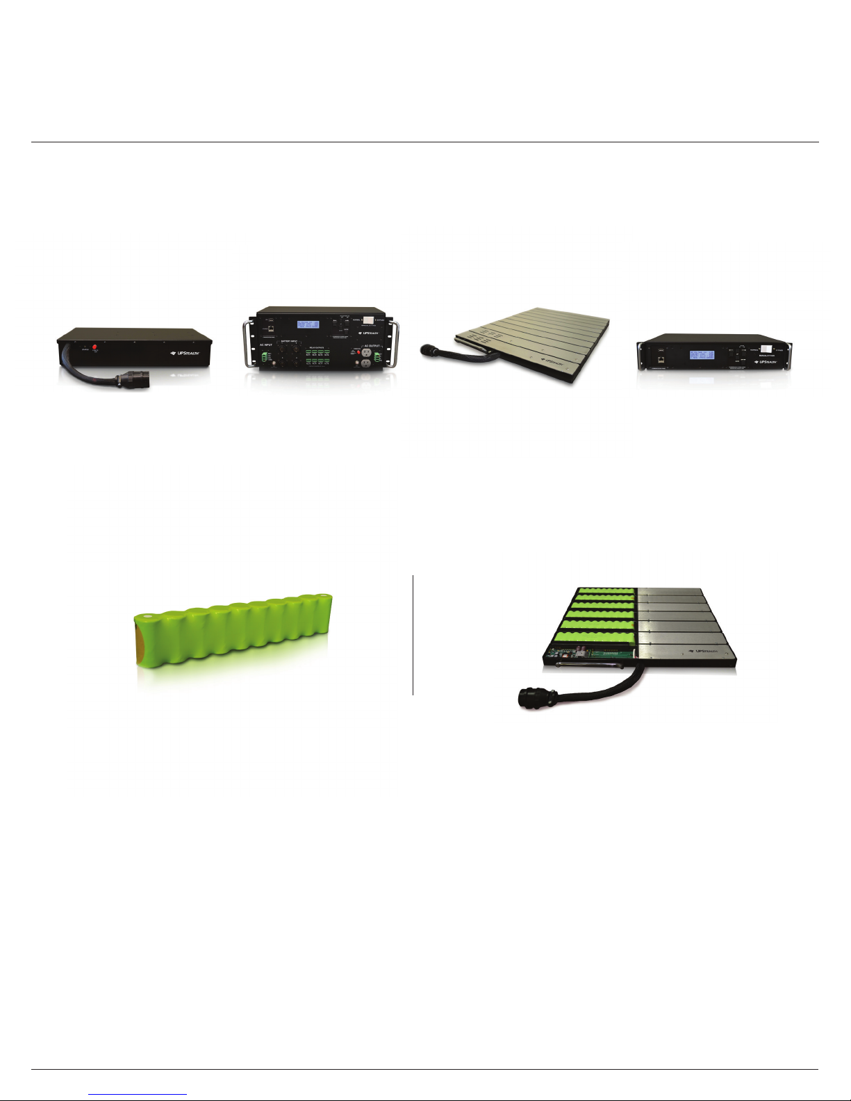
The UPStealth® system can be congured to match the power requirements of the trac cabinet. The minimum system would
include an Inverter/Controller and one Battery Panel. A large system could include one Inverter/Controller, four HUBs with up to
sixteen Battery Panels, and a PIM if there is a need to bypass the UPStealth® system while keeping utility power to the cabinet.
The connection between the Inverter/Controller and a Battery Panel is a single cable that contains all necessary signals. Circular
connectors make connecting the cables very easy. A similar cable connects the Inverter/Controller to the HUB.
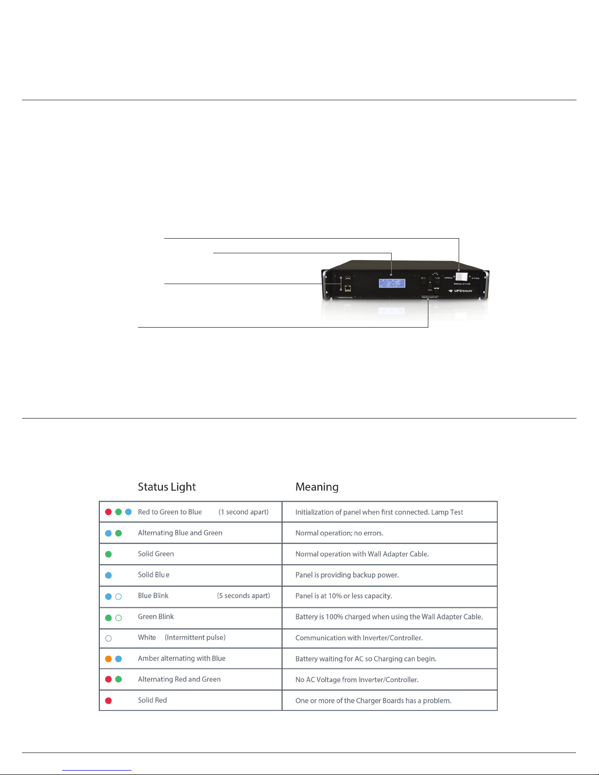
Inverter/Controller
The connections for the Inverter/Controller are the same whether you are using a NEMA style or the 170 style. The two
Inverter/Controller styles are electrically identical. The AC Input to the Inverter/Controller is usually connected to the utility
power directly or through a Power Interface Module (PIM). Agencies normally run the utility power through a breaker rst that
is located on the service panel. The UPStealth® Inverter/Controller has a 20 AMP breaker on its input and output for added
protection. It is recommended that 12 AWG or larger wire be used for power connections. The Phoenix Power connectors can
handle up to 8 AWG wire.
Adding a second Terminal Block Service (TBS) to the service panel can greatly simplify wiring to the UPStealth®. The second
TBS is used to run power up to the UPStealth® AC Input and the AC Output from the UPStealth® is connected to the original TBS
block. Electrical equipment that you don’t want connected to the UPStealth® can be connected to the added TBS block. The
Inverter/Controller output is not connected to the utility power in any way when operating from battery power. To keep them
separated, you should not connect the AC neutral from the UPStealth® to the AC Neutral of the utility power.
IMPORTANT: If the UPStealth doesn’t power up after the AC power is turned on, check and make sure that the AC Power is
connected correctly. The unit will not power up if the AC power line is connected to its “AC OUT” terminals.
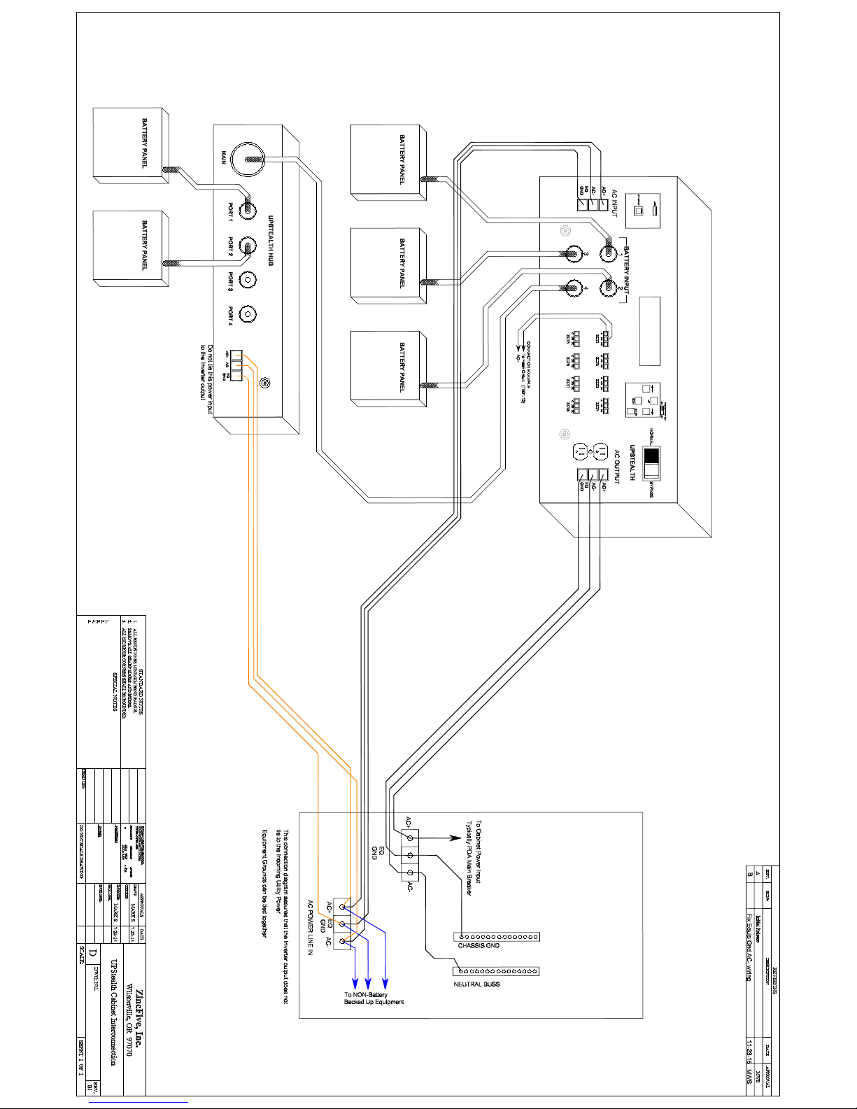
When a PIM is used in a system, all connections are made to the PIM. A special cable is used to connect the PIM to the
UPStealth®. The utility power is connected to the“AC LINE IN”connector on the PIM either directly or through the second TBS
block. The PIM connector labeled “AC to CABINET” is connected to the original TBS block or the AC+ pin goes to the PDA and
the AC- and Chassis Ground connect to the appropriate buses on the service panel. Figures 1 & 2 show how the various
modules in the UPStealth® system are connected together.
IMPORTANT: Make sure that the fan exhaust on the side of the enclosure is not blocked. The fan will come on when the
temperature of the enclosure reaches a preset threshold.
The UPStealth® NEMA Inverter/Controller can sit on a shelf or can be mounted in a 19”rack with the mounting ears. Make sure
that the vents and the fan outlet on the sides of the unit are not blocked by other components when sitting on a shelf.
Power connections are made with nger safe Phoenix Power connectors. These connectors are keyed to prevent the
power wiring from being plugged into the wrong connector. Pulling on the connector or wire cannot unplug these connectors.
The connector has two release slides that must be pushed toward the receptacle before the connector can be removed.
IMPORTANT: When using stranded wire, DO NOT solder the wires that are inserted into the phoenix connector. Soldered wire
can loosen with time. The Inverter/Controller also has a standard duplex receptacle to plug the Controller or other equipment
into the Inverter/Controller directly, if desired.
Figures 1 & 2
UPSTEALTH® USER MANUAL / 6


Installation
Inverter/Controller
The Inverter/Controller has a Real Time Clock that has its own back up power supply that uses Lithium Coin Cells and Super Caps.
The Super Caps will back up the RTC for 24 to 48 hours. The RTC will automatically switch to the Lithium cells when the Super
Caps have discharged. A small slide switch located above the keypad turns the power to the RTC ON and OFF. UPStealth® is
shipped with the switch in the OFF position. DO NOT turn the switch ON until the UPStealth® is powered up and operating. The
UPStealth® has to congure the RTC before the battery power is enabled or the batteries may be prematurely discharged.
When power is rst applied to the Inverter/Controller, the UPStealth® checks the power line, load current and updates the
display. If an Ethernet board is detected, it is also initialized which may take a minute. The UPStealth® then determines how
many battery strings (one set of cells that make up a 48 VDC battery) are connected in the system. It doesn’t matter how the
battery strings are physically arranged, just the total number and their charge state. The Inverter/Controller turns the AC power
on to each of its ports to make sure each panel in the system can power up even if the battery voltage is too low to operate
normally.
Once the Battery Panel count (and battery string count) is determined, the UPStealth® will enter a recovery period where the
battery strings are charged up to a minimum voltage level before they are allowed to supply current to the Inverter/Controller.
This may take a few minutes.
Once the recovery voltage threshold is reached, the capacity is calculated and the battery panels are turned on to supply power
to the Inverter/Controller. When the Inverter/Controller is up and running the Battery Panels go into the normal operating mode.
The Inverter/Controller will then turn the AC oto any unused ports. The UPStealth® scans all of the ports regularly to check to
see if any Battery Panels have been added or removed.
When a utility power“event” happens, all of the battery strings are alerted at the same time to turn on their outputs. This
happens within a few microseconds. All of the battery string outputs are combined together to form one large battery. A dead
or partially discharged battery panel will not drag down the other panels. Each battery string is current limited to prevent one
battery string from supplying all of the power.
When the AC power is restored, the UPStealth® looks for good power (stable wave forms) for 3 minutes before returning to utility
power. This prevents switching back and forth between the Inverter/Controller power and utility power if the restored AC line
voltage is “noisy”.
The UPStealth® determines whether a power failure has happened by two methods: the true RMS value of the AC Line voltage
and/or the occurrence of a“transient” large enough to cause power disruptions. The trip points for the lower and upper
voltage thresholds are set by the user. The user can also select “transient” sensitivity levels that determine if the UPStealth® will
respond to a power line anomaly.
The UPStealth® determines that a power event has occurred by comparing the incoming power line waveform to a saved
template. This template is created by monitoring the local power line and building a waveform based on the actual local AC
power. The template is continuously updated since the wave shape can change based on the power line loading in the area. The
UPStealth® looks for a voltage change for a dened amount of time before it decides a power failure has occurred. The waveform
that tripped the UPStealth® is saved in the Event Log along with the template waveform, so power problems can be analyzed.
The “BYPASS” rocker switch on the front panel allows the user to bypass all of the electronics in the Inverter/Controller. The
switch directly connects the “AC INPUT” terminal block with the “AC OUTPUT” terminal block when in the Bypass mode. The
UPStealth® will still be operating and it can still monitor the cabinet load current and power. The Inverter/Controller will still
control the Battery Panels and make sure that they are maintained properly. The main purpose of the switch is to bypass the In-
verter/Controller if the user feels it is not operating correctly or the user doesn’t want the battery backup system to operate while
they work on the cabinet.
Figures 1 & 2
7 /UPSTEALTH® USER MANUAL

UPStealth® NEMA Battery Panel (500W)
UPSTEALTH® USER MANUAL / 8
Battery Panels
The Battery Panels come in two dierent
physical enclosures. The Living-Hinge Battery
Panels come in exible plastic enclosures that
are designed for easy installation by sliding
between the cabinet rack and the outside shell
of the cabinet. They need to be exible to get
around the rack during installation. The cabinet
size determines which Battery Panel to use and
how many you can put on a side.
The NEMA style batteries are in aluminum cases
and are made to sit on or underneath a shelf.
They can also be rack mounted with the
supplied mounting ears. All of the Battery
Panels are electrically identical.
Installation
UPStealth® Living-Hinge Battery Panels are installed by rst putting the included plastic block in the bottom of the area between
the rack and outside shell. Slipping the “Speedy Sleeve”in the space next to the rack will allow easier installing for the Battery
Panel by covering protruding screws. The Battery Panel can be installed from the front or the back of the cabinet. The metal
cover side should face the rack. In larger cabinets, one panel can sit on top of another. The Living Hinge Battery panels can be
used in any orientation.
The Battery Panels can contain any number of battery strings but typically have four or six battery strings. Each Battery Panel
has an intelligent controller that gathers data from each battery string, which is relayed back to the Inverter/Controller. Entering
into power fail mode is independent of the panel controller, so the battery strings can respond very quickly to a power failure.
This system conguration allows the individual battery strings to supply power to the Inverter/Controller even if communication
is lost between the Battery Panel, the Controller, each Charger and/or the Inverter/Controller. Each battery string has its own
Controller/Charger that maintains the battery cells. The charger section operates oof the AC line. This makes the charge time
independent of the number of battery panels in the system since each battery string has its own charger. The recharge time is
four hours worst case.
The Battery Panels can be recharged without connection to the main Inverter/Controller using the special included Wall
Charging Adapter. This cable can connect to standard wall AC outlets independent of the Inverter/Controller. The cable can be
left plugged in indenitely without damaging the battery cells. The Battery Panel intelligence will maintain/protect the battery
cells.
UPStealth® Living-Hinge Battery Panel (500W)

HUB
The expansion HUB allows the installation of more than four UPStealth® Battery Panels to a single Inverter/Controller. The HUB
connects to one of the 4 circular connector ports on the back or front of the Inverter/Controller and can control four additional
Battery Panels. Therefore, you can have up to sixteen Battery Panels in a system when you have 4 HUBs installed to an
Inverter/Controller. Each HUB has its own AC power input to supply charging power to the Battery Panels. The AC power
connector should be tied to the utility power and not the BBS/UPS power. During a power failure, the HUB gets its power from
the batteries.
When connecting a system, you should always connect some batteries directly to the main Inverter/Controller before
connecting Battery Panels to the HUB.
The HUB mounts to the rack rails in a standard cabinet. The status indicator is the same as the Battery Panels except that during
a power failure the status LED is a slow blinking Blue.
Installation
Battery Panels
As soon as any cable is connected to the Battery Panel, the panel will turn on. If the other end of the cable is not connected to an
Inverter/Controller port or plugged into an AC wall outlet, the Battery Panel will slowly discharge.
IMPORTANT: Do not connect a cable to the Battery Panel if the other end of the cable is not going to be plugged in. The Battery
Panel will eventually completely discharge and shut itself owhich will reduce the life of the panel.
Battery Panels can be added or removed at any time in a system. Adding a discharged panel to a system will not hurt the
system. The UPStealth® will adjust the capacity and run times when the UPStealth® system detects the change in battery strings.
The Battery Panel rating, “300 Watt” and/or “500 Watt” is based on a discharge time of 2 hours. A 500 Watt panel will supply a 250
Watt load for 2 hours. The same 500 Watt panel will supply a 500 Watt load for about 45 minutes.
The UPStealth® has a“Force On” mode that allows you to supply power during a power failure to equipment that is not already
connected to a UPS system. To use this feature, install the UPStealth® as you normally would. Because there is no AC available
the UPStealth® will not start up on its own. To start the system you will manually have to turn the Battery Panel(s) on and then
force the Inverter/Controller on.
After the connections are all made, hold the“Force On” button on the Battery Panel for 5 seconds. The LED Indicator should
show Blue. You may want to do the same for the other Battery Panels if installed. Next, go to the Inverter/Controller and hold the
“Force On” button until the beeping stops. You should now be up and running. Do not use the “Force On” feature if AC is avail-
able.
The Battery Panels continuously monitor the condition of the battery cells, including temperature, discharge current and
charging proles, so the user gets the maximum life from the Battery Panels. To insure maximum battery life, the control
electronics may extend the charge cycle of the battery strings beyond the normal four hours.
9 /UPSTEALTH® USER MANUAL

PIM
The Power Interface Module (PIM) connects between the cabinet and the UPStealth®. The PIM allows the UPStealth® to be
removed or disconnected from the cabinet without removing the power from the cabinet. The UPStealth® connects to the PIM
with a plastic circular connector making it easy to disconnect the UPStealth® from the cabinet. The utility power is connected
to the AC INPUT Terminal Block and the cabinet is connected to the “AC TO THE CABINET”Terminal Block. With the PIM switch in
the “NORMAL” position, power to the cabinet comes through the UPStealth® and can provide battery backup. When the switch is
in the “BYPASS” position, power to the cabinet comes from the AC INPUT terminal block and the UPStealth® does not supply any
power to the cabinet. The PIM mounts to a rail in the cabinet with the mounting brackets supplied.
User Interfaces
There are two primary ways to directly interact with an installed UPStealth® while standing in front of the trac cabinet: the
front panel LCD display and keypad on the front of the Inverter/Controller or by connecting through the Ethernet port with a
laptop with the installed RTi Connect™ desktop application. Once connected through the Ethernet port, the technician can see
and manage the UPStealth® parameters menu. In addition, a technician can also connect to an installed UPStealth® remotely, as
long as the installed UPStealth® is connected to a network (see RTi Connect™ Manual).
Inverter/Controller User Display
The main user interface is the Inverter/Controller front panel keypad and the LCD Display. By moving the cursor on the display
with the “ENTER” key, you can highlight and select menu items. The arrow keys allow you to change the value of the item
selected.
The LCD Display has several screens that allow the user to see all of the status information or set operating parameters of the
system. The following is an overview of each display:
Installation
UPSTEALTH® USER MANUAL / 10

Main Status Screen
Normal Status Display
Description:
Primary Status screen shown on power up. The
cabinet status is shown here.
Normal Status Display:
• AC Voltage In: The TRMS AC voltage going into the
BBS/UPS and powering the system.
• Cabinet Load: Shows the overall
intersection power draw.
• Backup: The shown time (HH:MM) represents the
available backup time based on the cabinet load.
The percentage represents the overall charge state
of the batteries.
Power Failure Display
If a power failure occurs the following display is shown:
Force On Display
If the UPStealth® is started up with the
“Force On” switch, the display will rst show:
The display will automatically switch to the Power
Failure Display after the UPStealth® has initialized itself.
Controls:
• To get to the main system menu, press Enter.
• No other controls on this screen.
Normal Status Display
Power Failure Display
Force On Display
11 /UPSTEALTH® USER MANUAL

System Menu Overview
Description:
The main system menu. All conguration options can be reached from this screen.
On This Display:
• TIME/DATE: Set the Inverter/Controller date and time clock.
• CONFIG: Set the UPStealth® to Operate in Standard or High capacity mode.
• PANELS: View panel detection mode which displays connected panels to verify system conguration.
• RELAYS: Brings up the screen for viewing and setting relay triggers.
• EVENT LOG: Shows the past 74 system events, such as, power failure, conguration change, internal error, etc.
• MORE: Provides access to the AC Switch and Ethernet Menus
• INVERTER: Allows for conguring and viewing the brownout thresholds and power monitor sensitivity.
• BACK: Returns to the Main Screen.
Controls:
• Use the direction keys to move the cursor.
• To select an option, move the cursor over the appropriate title and press ENTER.
System Menu Display
UPSTEALTH® USER MANUAL / 12

Time & Date Menu
Description:
This is the screen for setting/viewing the time and date of the system. This clock is used for all time stamps on events and
time-based relay triggers. This clock uses military time.
On This Display:
• T: The current system time, displayed as hh:mm:ss (hh = 0 to 23)
• D: The system day, displayed as MM/DD/YY.
• SET: Change the date and time of the system.
• BACK: Returns to the main system menu.
Controls:
To set the time:
• Move the cursor over SET, and press ENTER.
• The cursor will now move into the time area of the screen.
• Press UP/DOWN to change a value. If it reaches a maximum or minimum value, the value will “rollover” (e.g, if UP is pressed
when the minutes is 59, it will go to 0).
• Press LEFT/RIGHT to select a value, such as hour, min, day, etc.
• When nished, press ENTER to save The changes. The cursor will return to the BACK option.
Notes:
• The seconds of the system cannot be set.
Time and Date Menu Display
13 /UPSTEALTH® USER MANUAL

Relay Selection & Trigger Viewing Menu
Description:
View all 8-relay settings and select a relay to congure. This display is congured as two columns, one column has the relay
number (under the STATUS heading) and the second column shows the Trigger for enabling the relay. When a RELAY is enabled,
The COM pin and the NO (normally open) Pin are connected.
On This Display:
• RELAY(#): Brings up the settings menu for that relay.
• TRIGGER: What the relay will trigger on. Values can be:
In the below screenshot, Relay1 is not congured to trigger, Relay2 will trigger on a power failure.
Controls:
• Use the direction keys to select a relay. Press ENTER to go to the conguration screen for that relay.
• The screen scrolls, allowing access to all the relays. BACK will always be at the very top, and the last relay will always be at the
very bottom.
Relay Selection and Trigger Viewing Menu Display
AC
TEMP
TIME
FLASH
BATTCAP
MULTI
UPSTEALTH® USER MANUAL / 14

System Description & Relay Setup
System Description
The UPStealth® has 8 user-congurable relays that can trigger on a power failure, time of day, temperature, ash time, and at a
given battery capacity.
Each relay can be assigned to any of these triggers. Likewise, any relay can have more than one trigger type, in which case the
relay will trigger if any of the conditions occur.
When conguring a relay, each trigger is turned on separately for that relay. On factory default, all triggers for all relays are o.
The left side is known as the “Common Panel”, and the right side is the “Trigger Panel”. These are divided by the vertical dashed
line. There is a unique trigger panel for each trigger option.
Settings such as temperature bounds
and times will be saved even when a
trigger is turned o.
The following information is common
to all applicable conguration screens.
Relay Setup and System Display
UPStealth®Interface
Common Panel
Except when saving, this will be displayed on the left side of the screen.
On This Display:
• RLY (#): The relay that is being congured. This will always be present
on every relay conguration menu.
• NEXT: Moves to the next trigger conguration panel (Such as from AC
to TEMP).
• SET: Congure the trigger for the relay. This will move the cursor into
the trigger panel, allowing for input of conguration options.
• BACK: Returns to the relay selection screen.
Controls:
• Select one of the options with the directional arrows; press ENTER.
15 /UPSTEALTH® USER MANUAL
Table of contents
Other ZincFive UPS manuals
Popular UPS manuals by other brands

Vertiv
Vertiv Liebert PSA4 Installer/user guide

WÄRTSILÄ
WÄRTSILÄ JOVYCUBE 160 operating manual

Vertiv
Vertiv Liebert EXS Quick installation guide

LEGRAND
LEGRAND Daker DK 4.5 kVA installation manual

AEG
AEG PROTECT D LCD+ user manual

Alpha Outback Energy
Alpha Outback Energy CableUPS XM3V-HP quick start guide