Zinco Fallnet SR Quick guide

Fallnet®SR
Installation and Instruction Manual and Inspection

2
4. Positioning the grid and the Anchor Point
5. Connecting the four grids and check the position
List of Contents
Procedure
6. Applying the required load (min. 110 kg/m²)
3. The grid must fully cover the base plate and the vertical locking
tabs must engage the adjacent elements
Installation Manual Page 3
Instruction Manual Page 5
Details on Manufacturer Page 6
Inspection Chart Page 7
1. Measuring the position of the anchor point 2. Place the marked grid over the anchor point and click into place
>110 kg/m²

ZinCo GmbH ∙ Lise-Meitner-Strasse 2 ∙ 72622 Nuertingen ∙ Germany
Phone +49 (0) 7022 6003-0
Email: [email protected] ∙ www.zinco-greenroof.com
3
1.33 m
1.00 m
6
5
- Load bearing element (2.00 x 2.67 m) consisting of four
pre-assembled grids to hold the load.
Important:
We would like to state explicitly that, regardless of product
liability, ZinCo shall only assume liability for the consultancy
process where installation has been carried out in line with
ZinCo planning. Installation without planning carried out by
ZinCo is at your own risk. Regardless of this, the installation
manual and instruction manual must be observed.
Please check the following prior to installing the anchor device
Fallnet® SR:
0.1 Delivery scope / condition of the system components
Check: that the shipment is complete and in perfect condition.
Important: incomplete, faulty or incorrect shipments should
be reported immediately.
The delivery scope per Fallnet®SR consists of:
- anchor point:
Installation Manual
1. Base plate with
vertical locking tabs
2. Support
3. Anchor eye
4. Identification label
4
3
1
2
5. Four pre-assembled
grids à 1.00 × 1.33 m
6. Marker and device
for correctly
positioning the
single anchor point
0.2 Check the situation before installation
Prior to installation please check that the roof construction is
sufficiently dimensioned for the required loads, waterproofing
and if required root barriers are in place and the actual sub-
base for the Fallnet® SR is properly and evenly laid and is not
steeper than 5 degree (=8,8 %). If you are in any doubt, please
clarify prior to installation. The surface must be free of dirt, oil
and moss or lichen prior to installing Fallnet® SR. If necessary,
sweep the surface.
0.3 General points
The Fallnet® SR can be installed, for example,
- On the protective layer above the waterproof layer
(e.g. ZinCo protection mat SSM 45 with single-course
green roof or ZinCo Filter Sheet TG with a gravel roof)
- Please ensure that there are no objects (e.g. concrete
slabs) in the area of the Anchor Point (radius of at least 0.5 m
- on the filter sheet (e.g. for multi-course green roof)
- Also ensure that the bulk material to be used as the
load on the Fallnet® SR extends at least 50 cm beyond
all four edges of the grid elements
Important:
The Fallnet® SR must always be in direct contact with the
load (bulk material)! It must, therefore, be filled and covered
completely with suitable bulk material (UV protection!).
Zincolit or ZinCo system earth, gravel or some other similar
bulk material can be used. Must only be installed on roofs
with a pitch of a maximum 5 degrees ( = 8.8 %)!
The required load (dry weight) for Fallnet® SR is at least
110 kg/m². This is to be increased to 130 kg/m² if the roof
pitch is greater than 2° (3.4 %) and it is possible to fall in the
direction of the slope.
Where the Fallnet® SR is to be incorporated into a green roof,
a min. 300 mm wide gravel strip should be left all around the
Anchor Point, so that it is easier to see.
1.1 Measuring The Anchor Point
Measure out the position of the Anchor Point using a roof site
plan. Please ensure that the anchor eye is positioned at a
distance of at least 2.50 m from the roof edge.
1.2 Connect marked grid with Anchor Point
Place the punched opening in the middle of the coloured
element of the pre-assembled grid (1.00 × 1.33) over the
anchor point. Gently click into place using your foot, so that
it fully covers the base plate and the vertical locking tabs on
the base plate engage behind the outer bar of the adjacent,
black grid.
1.3 Positioning the grid and Anchor Point
The grid and anchor point are positioned over the measured
point (see 1.1).
1.4 Connecting all four grids to each other
Then, connect the other three grids in such a way that the
Anchor Point is in the centre of the connected grid area. The
four pre-assembled grids provide a base area of about 5.3 m² in
total. The Fallnet® SR must be placed fully on a level surface,
all connection points must be clicked into place. The connec-
tion points can be separated again using a hammer. Faulty
elements must be replaced.
1.5 Applying the required load
The installed Fallnet® SR is now filled and covered with the
load (e.g. ZinCo System Substrate or gravel), for requirements
see item 0.3 General Points.
2. Adapting to building-specific features
With Fallnet® SR, the form (2.00 × 2.67 m) specified in the
Standard can be adapted to suit the particular building
situation, where necessary.

ZinCo GmbH ∙ Lise-Meitner-Strasse 2 ∙ 72622 Nuertingen ∙ Germany
Phone +49 (0) 7022 6003-0
Email: [email protected] ∙ www.zinco-greenroof.com
4
Schematic of a standard installation of the centred Anchor
Point with the four pre-assembled grids (à 1.00 × 1.33 m).
Installation with obstacles
2.67 m
2.00 m
Fall Edge
min.
2.50 m
Installation Manual
By moving the individual grid elements around, rising building
elements or ventilation shafts, drains etc. can be embedded.
Please note that the anchor point must not be positioned in
either of the two outside grid rows. In addition, the Anchor Point
must be placed in the centre of a grid element (0.33 × 0.33 m).
In the stress direction, at least 20 grid elements must be behind
the Anchor Point. We recommend having ZinCo plan and
inspect such non-standard installation situations.
3.1 Completion, identification label
Please ensure that all works have been carried out satisfactorily
and that the identification label can easily be seen and read.
Only anchor devices that have an identification label may be
used.
2.67 m
Schematic (standard)
Fall Edge
Cover with bulk material to extend
at least 50 cm beyond the grid
48 grid elements
à 0.33 x 0.33 m Anchor Point
mind.
2.50 m
2.00 m
3.2 Installation documentation
The installation documentation is proof for the client that the
installation has been carried out correctly and professionally.
This documentation is also an essential basis for subsequent
inspections of the Fallnet anchor device(s). A copy of the
installation documentation is available in PDF from the
manufacturer. On completion of installation, copies of the
document are to be given to the client and are to be retained
on the property for subsequent inspections of the Fallnet.
The following information is a minimum requirement for the
installation documentation:
- address of property
- installation company
- technician responsible for installation
- fallnet serial numbers
- details of load (which bulk material, load weight, include
delivery note, if relevant)
- installation plan (please include serial numbers here too)
The installation plan should be affixed to the building where it
is clearly visible, e.g. at the roof access point.
Statement issued by the technician responsible for installation
(signature):
- the Fallnet installation manual was adhered to
- installation was carried out as planned
- minimum load requirements have been adhered to
- photo documentation, in particular of details that are no
longer visible after installation.
3.3 Handing over the Fallnet®SR documentation to
the client/ owner
The delivery scope includes the following documents, which
the installer must hand to the client:
- Installation Manual and Instruction Manual
- Inspection chart. Please record the serial number of the
Fallnet® SR in the chart. This number can be found on
the identification label attached to the product. Fallnet® SR
must be inspected regularly.
In addition, the following must be given to the client:
- Installation documentation
- Site plan
3.4 Queries
Should you have any queries, or be unsure about the correct
use/installation of the product or require further detailed
information for your own specific building project, please
contact ZinCo GmbH.

ZinCo GmbH ∙ Lise-Meitner-Strasse 2 ∙ 72622 Nuertingen ∙ Germany
Phone +49 (0) 7022 6003-0
Email: [email protected] ∙ www.zinco-greenroof.com
5
Instruction Manual
Your roof protects your building, the contents and any valuables
in it. In order to have the benefit of a fully-functioning roof over
a long period of time, your roof must be installed professionally
and must be inspected at regular intervals during its lifetime
and, where necessary, repair work carried out. Therefore, it
is important to ensure that any works on the roof are carried
out safely. The client (and later on possibly other) owners also
have a duty here and are responsible for adherence to any
regulations pertaining to occupational safety on a roof.
Used in combination with a load of suitable material (e.g. green
roofing, substrate or gravel), Fallnet® SR provides an Anchor
Point in accordance with EN 795:2012 Type E for fall prevention
on flat roofs.
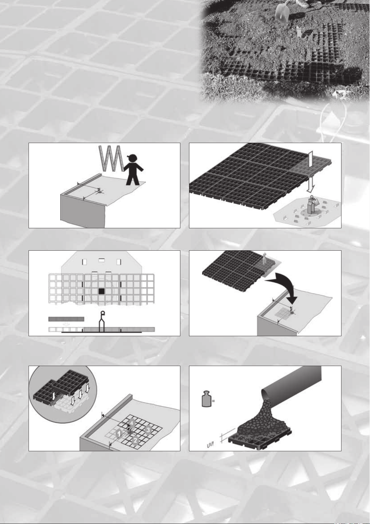
1.Fallnet®SR system components:
a. Anchor Point
Fully factory-assembled, consisting of anchor eye, approx.175 mm
high support and base plate in metal, size 0.75 × 0.75 m,
with vertical locking tabs. The identification label (incl. serial
number) is permanently attached to the anchor eye.
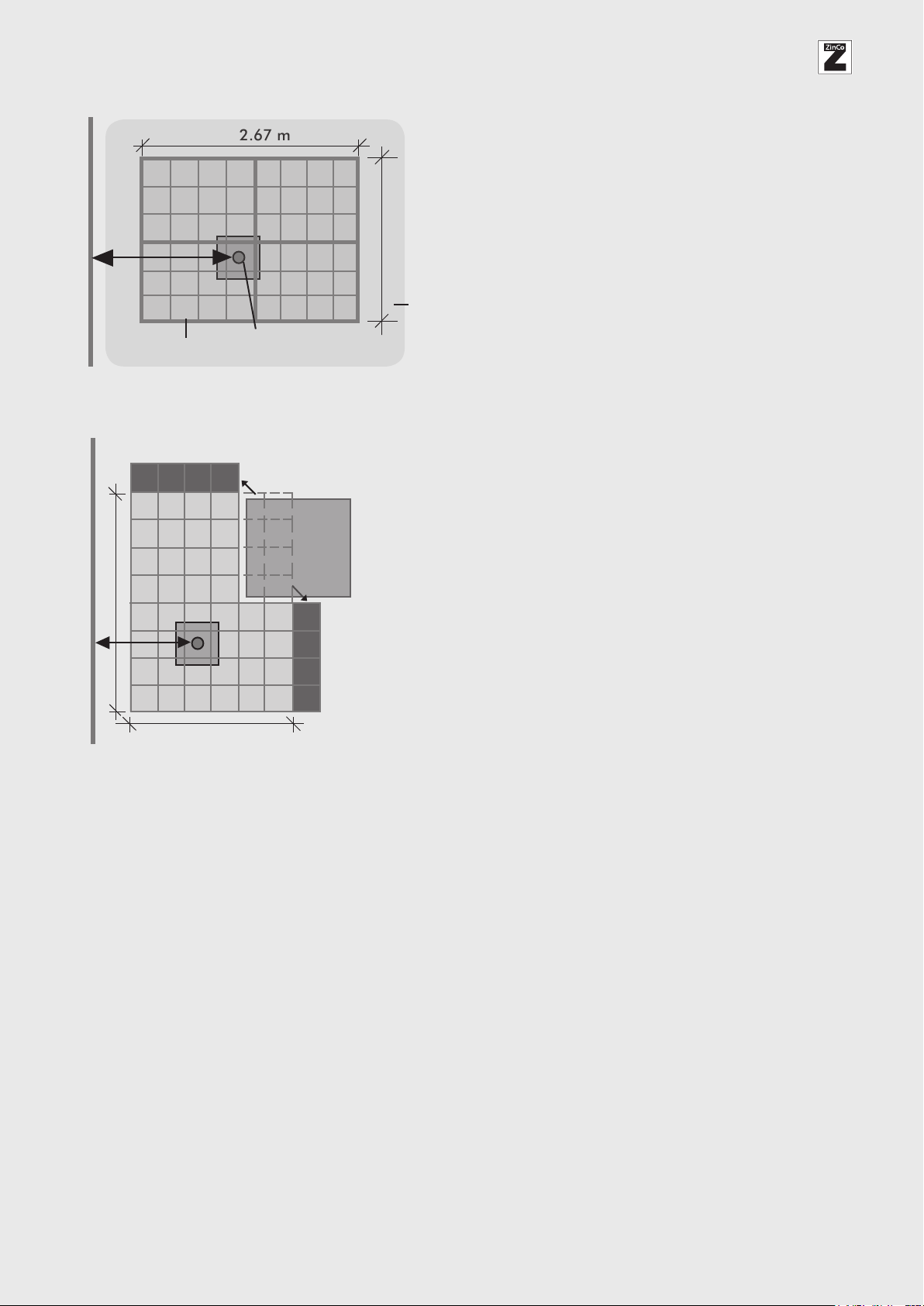
b. Load-bearing element, 2.00 × 2.67 m
Consists of four pre-assembled grids à 1.00 × 1.33 m. One
of these elements has a label and a device for the standard
positioning of the single anchor point. In total, 48 individual
grid elements (0.33 × 0.33 m) with click connections around
the edge. Height approx. 30 mm.
c. Documents
The delivery scope includes the following documents, which
the installer must hand to the client:
- Installation Manual and Instruction Manual
- Inspection chart. Please record the serial number of the
Fallnet® SR in the chart. This number can be found on
the identification label attached to the product.
Fallnet® SR must be inspected regularly.
In addition, the following must be given to the client:
- Installation documentation
- Installationplan
2. Scope and requirements for use
Fallnet® SR must only be used for the intended purpose as an
Anchor Point for personal protection equipment. Fallnet® SR
must not be used for lifting weights or for attaching objects.
Any modification or addition to any of the system components
requires the prior written permission of the manufacturer.
Please note also:
- Fallnet SR must only be used by 1 person at a time
(max. 100 kg, including equipment).
- it must only be used for a roof pitch of maximum 5°
- it must only be installed on a suitable subsurface, i.e.
either on a filter sheet (multi-course build-up) or on a
protection mat or layer (single-course build-up), see
Installation Manual).
Important: Direct contact with the load (bulk material) is
required at all times.
impact is prevented.
- to be used only with suitable personal protection equipment
(PPE) for use on the horizontal. Such PPE in compliance with
EN 363 (not part of the anchor point Fallnet® SR) must
contain the following components:
- Safety harness in compliance with EN 361
- Fall absorber in compliance with EN 355 or safety appliance
for use at height in compliance with EN 360 (Arresting
forces each ≤ 6.0 kN)
- Connecting device EN 354
- Connection elements (carabiner) in compliance with EN 362
Please ensure that the individual system components are
compatible and suitable for use on the horizontal and for a
fall event over a roof edge. Potential danger resulting from a
combination of the components used (in particular fall absorber,
EN 355 or safety appliance for use at height, EN 360) should
be eliminated. Therefore, prior to using personal protective
equipment for fall arrest we recommend that you seek the ad-
vice of the manufacturer of the personal protective equipment.
Please observe the manufacturer’s Instruction Manual.
The Fallnet® SR anchor eye must be installed at a distance
of at least 2.50 m from the roof edge.
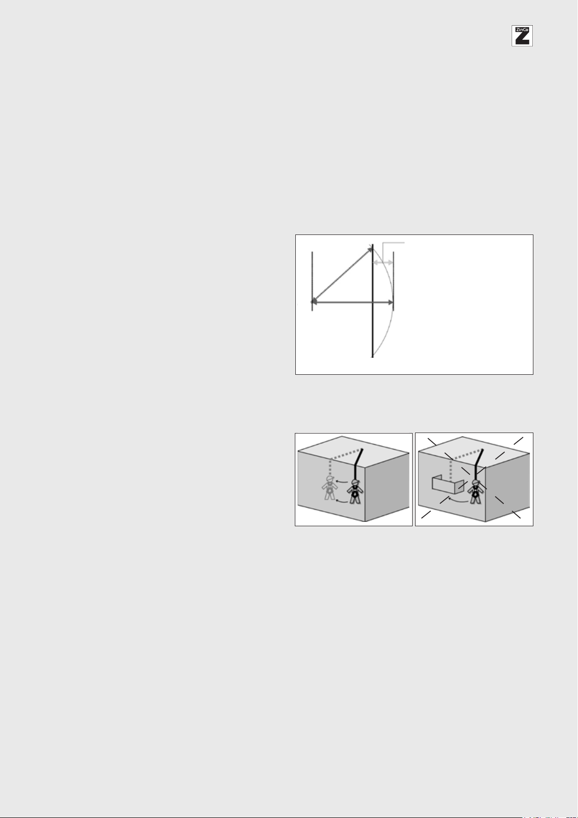
- the minimum fall distance to the ground (fall height) must
be such as to prevent a person hitting the ground in the
case of a fall event and to allow the person to swing freely.
The required minimum fall distance to the ground (potential
impact area) is calculated from the part distance of the
connecting device, which is drawn over the roof edge
(= largest possible rope length to the roof edge minus
shortest rope length, at a right angle to the roof edge), the
height of the person attached to the anchor point, the
distance for the rope and safety harness stretch, rupture
distance of fall absorber, the moving of the anchor device
(max. 1,0 m)
+ Free fall (rope length over roof edge)
+ Height of person attached
+ Stretch of rope
+ Stretch of safety harness
+ Rupture distance fall absorber
+ Deformation and displacement of
anchor point (max. 1,0 m)
+ 1.0 m Safety
__________________________________
= minimum distance to ground
Rope length over roof edge
Fall Edge
Anchor Point
and an additional 1.0 m as safety value.
- In the case of a fall arrest event, the person may swing to
and fro. It is important to ensure that there are no building
elements in the way (e.g. balcony, awning etc.) and that

ZinCo GmbH ∙ Lise-Meitner-Strasse 2 ∙ 72622 Nuertingen ∙ Germany
Phone +49 (0) 7022 6003-0
Email: [email protected] ∙ www.zinco-greenroof.com
6
Instruction Manual
The following hazards may impact the proper functioning of
the equipment: e.g. putting stress on the connection devices
due to sharp edges, cuts, abrasion, slack rope, chemical,
electric or climatic impact, extreme temperatures, swinging
movement in the event of a fall. The connection devices,
therefore, should always be inspected prior to use and if
necessary, an edge protector must be provided.
The anchor device may be used in frosty conditions provided
the device was installed in frost-free conditions.
3. Requirements for the use and for the user of
Fallnet®SR
The anchor point Fallnet® SR must only be used by persons
who have been instructed in the safe use of the equipment,
who have the necessary knowledge and who, in terms of their
health, are capable of using the equipment (e.g. no impairment
due to medication, alcohol abuse, coronary or circulatory
problems etc.).
The user is to be instructed such that s/he will carry out the
following visual and manual inspections of the anchor point
before each use:
- manual tensile loading and visual inspection of the visible
stainless steel components, the support and the anchor eye
- visual inspection of the load height
Indications that the good working condition of the
anchor point is restricted could be:
- the stainless steel parts (support and anchor eye) are
deformed, weakened, soiled or are not in their original
condition.
- the anchor point yields slightly when pulled
- there is an uneven level of material around the anchor point,
e.g. as a result of drifting
- the black grids are visible.
- Objects (e.g. also concrete slabs) in the area of the anchor
point (radius of at least 0.5 m) that would prevent the
supports folding over as planned.
If there are concerns about the safe condition or the pro-
per functioning of the anchor device, it must not be used
and the builder/the owner must be notified.
Under no circumstances should the device be used until
the situation has been clarified!
The individual anchor points are to be used in accordance
with the plan for use. If there is no utilisation plan available,
the length of the connection device of the PSA must always be
adjusted such that a possible fall is prevented or a swinging
fall does not result in impact. Prior to use, an emergency plan
must be available in which all possible occupational emer-
gency situations are addressed.
At the request of the client/owner, an inspection of the
proper functioning of the entire safety equipment is to be
carried out:
1. at least once a year
2. where required, e.g. if there is doubt about the proper
functioning of the equipment (see “Indications of
restricted functioning”)
3. after 10 years a complete inspection of the system
Fallnet® SR is to be carried out by the manufacturer.
The equipment must only be inspected by persons qualified
to do so and details of all inspections must be recorded in the
inspection chart.
It must also include the works listed under “Regular inspections”
(page 7). The relevant check list is available in PDF from the
manufacturer.
Attention:
After a fall arrest event, Fallnet® SR must be removed from
service immediately. Further use of the equipment is not
permitted. The product Fallnet® SR must only be used for the
purpose and application as described. The manufacturer
accepts liability for the product within the framework of
applicable statutory requirements.
The manufacturer accepts no liability for any other deviating
use of the product. Furthermore, the manufacturer accepts
no liability where the Installation Manual and the Instruction
Manual have been insufficiently adhered to. We wish to state
explicitly that, regardless of product liability, ZinCo shall only
assume liability for the consultancy process where installation
has been carried out in line with ZinCo planning. Installation
without planning carried out by ZinCo is at your own risk.
Where the anchor point Fallnet® SR is sold in another country,
the technician / user must make available a copy of the
Installation / Instruction Manual and the Inspection Chart in
the language of that country.
4. Label
Manufacturer: Zinco GmbH
Type: Fallnet® SR
Standard: EN 795:2012 Type E
Year manufactured: date of manufacture (year)
Serial no.: .................
Max. 1person: max. number of users
The notified body nominated for certification
Note that the Instruction Manual is to be observed
Fall protection equipment only to be used with a
fall absorber
5. Details of manufacturer and testing institute
Manufacturer:
ZinCo GmbH, Lise-Meitner-Strasse 2
72622 Nuertingen, Germany
Phone: +49 (0) 7022 6003-0
Email: info@zinco-greenroof.com
www.zinco-greenroof.com
Testing institute:
DEKRA EXAM GmbH
Dinnendahlstrasse 9
44809 Bochum, Germany
Notified body N.B. 0158

7
Used in combination with a load consisting of suitable bulk material, Fallnet® SR is an anchor device in compliance with
EN 795:2012 Typ E for fall protection on flat roofs. This device must only be used by a maximum of one person (up to 100 kg)
at any one time and in combination with personal protection equipment (PPE) in compliance with EN 363. The safety harness in
compliance with EN 361 must only be used together with tested and approved components.
Regular inspections
Inspections are required in order to ensure that the anchor device is functioning properly.
Such inspections must be carried out:
1. at least once a year
2. where required, e.g. if there is doubt about the proper functioning of the equipment
(see “Indications of restricted functioning”)
After 10 years a complete inspection of the system Fallnet® SR is to be carried out by the manufacturer.
The inspection works must be requested by the client/owner, are to be carried out by suitably qualified personnel who have been
authorised by the manufacturer and are to be recorded on the rear side of this inspection chart.
The following inspection works are required:
- visual inspection for damage and the position of the anchor device,
- visual inspection to ensure that there are no objects in the area of the
anchor point (radius of at least 0.5 m) that would prevent the supports folding
over as planned,
- manual inspection with regard to tensile loading of the anchor point, and
- sufficient coverage/bulk material height (see Installation Manual),
- legibility of the product identification label.
Attention:
Under no circumstances should the anchor device be used if there is any doubt as to its perfect condition and safety for use.
Please contact the client/owner immediately.
After 10 years, an overall inspection of the Fallnet®SR system is to be carried out by the manufacturer.
Product identification card in compliance with EN 365
Product Fallnet® SR
Manufacturer ZinCo GmbH, Lise-Meitner-Str. 2, 72622 Nuertingen, Germany
Building project
Serial number(s)
Purchase date
Installation date
Inspection Chart

8
Manufacturer:
ZinCo GmbH ∙ Lise-Meitner-Strasse 2 ∙ 72622 Nuertingen ∙ Germany
Phone +49 (0) 7022 6003-0
Email: [email protected] ∙ www.zinco-greenroof.com
Testing institute:
DEKRA EXAM GmbH ∙ Dinnendahlstrasse 9 ∙ 44809 Bochum ∙ Germany
Notified body N.B. 0158
Inspection Chart Fallnet®SR
Overview of documentation and plan of inspection works.
Building:.....................................................................................................................................................................................
..................................................................................................................................................................................................
Inspection Date Address Authorised company/
person
Comments: reason for inspection, defects
identified, repair work carried out
Date of next
inspection Signature
1st year
2nd year
3rd year
4th year
5th year
6th year
7th year
8th year
9th year
10th year Commission an overall inspection to be carried out by the manufacturer.
Inspected serial number(s): ..........................................................................................................................................................
Other manuals for Fallnet SR
1
Other Zinco Safety Equipment manuals