Zip Chillmaster- Installation & Operating Instructions - 81495 - January 2012 v1.00 Page 3 of 8
# Installation Instructions
Installing
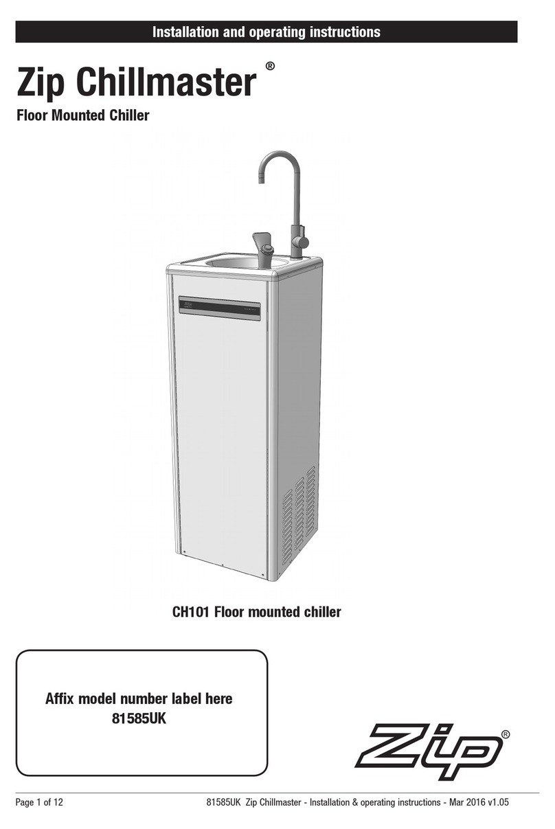
The Zip Chillmaster is an indoor unit and must not be exposed to the
elements of nature.
Leave at least a 50mm gap between the sides of the Chillmaster and any
walls or fixtures, to allow airflow through the vents.
The rear of the unit is flush mounted against the surface of a wall, so the
plumbing can pass through the wall or be recessed into the wall.
The illustration, on page 4, shows the exact dimensions for the piping entry
positions. A template is included with the unit.
Alternatively, the plumbing can be surface mounted and enter the
Chillmaster from beneath. You will need to examine the location to
determine the most appropriate method of installation.
Mounting to the wall
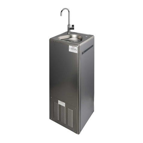
Unpack the Chillmaster taking care not to scratch the finish. Unscrew the
4 phillips head screws (2 on each side) that hold the bowl top in position.
Carefully lift and hold the bowl up and away from the casing taking care
not to scratch it.
Undo the John Guest (JG) push fit tee that joins the tubes of the bubbler
and carafe filler, from the tube that is coming up from the chiller outlet.
Once disconnected, place the bowl and screws safely aside. The
Chillmaster is attached to the wall through its top rear bracket. The fixing
holes are located equally off center, a total of 145mm apart and 47mm
below the top edge of the unit.
Use a tape measure and pencil to mark the mounting positions on the wall
where you propose to attach the Chillmaster.
Use a spirit level to ensure straightness. Accurate dimensions are shown in
the illustration on page 4. A template is also supplied.
You must supply and use screws, bolts or fixings appropriate to the type
of wall material you are attaching the Chillmaster to. They must be able to
support the weight of the Chillmaster, the water it contains, and somebody
leaning on it.
Plastic plugs are not suitable. Two 1/2” masonry anchors are supplied with
the unit for use in solid brick walls only.
Drill a 1/2” hole at least the full length of the anchor.
If attaching to a stud wall, properly fit a horizontal nogging with a
centreline of about 873mm above finished floor level.
Mark out and install the cold water line and drainage piping to the
positions as shown in the diagram and on the template.
It the electrical supply is to be concealed, have it installed to the position
centrally 40mm above the finished bottom level of the Chillmaster.
Screw the Chillmaster to the wall through the 2 fixing holes in the top rear
bracket.
Do not refit the bowl top until the services are connected.
