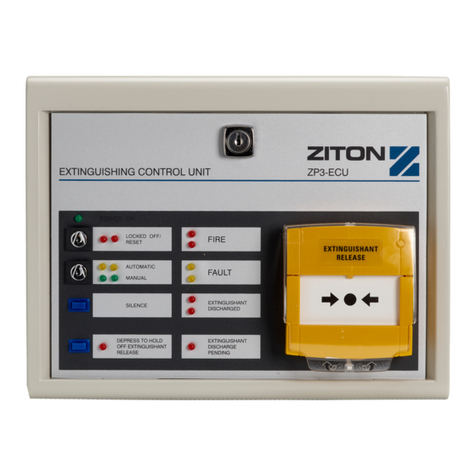
Ziton ZP3-ECU Guide

ZP3-ECU Extinguishing
Control Unit Installation
and Commissioning
Manual
P/N 503-0800ZE-I-05 • ISS 31JUL23

Copyright
©
2023 Carrier. All rights reserved.
Trademarks and
patents
The
ZP3-ECU name and logo are trademarks of Carrier.
Other trade names used in this document may be trademarks or
registered trademarks of the manufacturers or vendors of the
respective products.
Manufacturer
Carrier
Manufacturing Poland Spółka Z o.o.
Ul. Kolejowa 24. 39
-100 Ropczyce, Poland.
Authorized EU manufacturing representative:
Carrier Fire & Security B.V.,
Kelvinstraat 7, 6003 DH Weert,
Netherlands.
Revision
05
Conformity
2014/30/EU (EMC Directive). Hereby,
Carrier declares that this
device is in compliance with the essential requirements and other
relevant provisions of Directive 2014/30/EU.
2012/19/EU (WEEE Directive): Products marked with this symbol
cannot be disposed of as unsorted municipal waste in the Eu
ropean
Union. For proper recycling, return this product to your local supplier
upon the purchase of equivalent new equipment, or dispose of it at
designated collection points. For more information see:
recycleth
is.info.
2006/66/EC (Battery Directive): This product contains a battery that
cannot be disposed of as unsorted municipal waste in the European
Union. See the product documentation for specific battery
information. The battery is marked with this symbo
l, which may
include lettering to indicate cadmium (Cd), lead (Pb), or
mercury
(Hg). For proper recycling, return the battery to your supplier
or to a designated collection point. For more information see:
recyc
lethis.info.
Contact information
and product
documentation
For contact information or to download the latest product
documentation, visit
firesecurityproducts.com.

ZP3-ECU Extinguishing Control Unit Installation and Commissioning Manual i
Content
Important information ii
Safety issues and limitations iv
Chapter 1 System wiring 1
Wiring standards 2
Wiring connections 3
Chapter 2 Installation 13
Installation location 14
Installation procedure 15
Chapter 3 Commissioning 17
Introduction 18
Programming the ECU 22
Tests 27
Chapter 4 Technical specifications 28

ii ZP3-ECU Extinguishing Control Unit Installation and Commissioning Manual
Important information
This is the installation manual for the ZP3-ECU Extinguishing Control Unit (ECU).
Read these instructions and all related documentation entirely before installing or
operating this product.
Product compatibility
The ZP3-ECU is compatible for use with the following addressable fire alarm
control panels running the Ziton protocol:
• ZP3 Series
• ZP2 Series
• ZP2-A Series
Limitation of liability
To the maximum extent permitted by applicable law, in no event will Carrier be
liable for any lost profits or business opportunities, loss of use, business
interruption, loss of data, or any other indirect, special, incidental, or
consequential damages under any theory of liability, whether based in contract,
tort, negligence, product liability, or otherwise. Because some jurisdictions do not
allow the exclusion or limitation of liability for consequential or incidental
damages the preceding limitation may not apply to you. In any event the total
liability of Carrier shall not exceed the purchase price of the product. The
foregoing limitation will apply to the maximum extent permitted by applicable law,
regardless of whether Carrier has been advised of the possibility of such
damages and regardless of whether any remedy fails of its essential purpose.
Installation in accordance with this manual, applicable codes, and the instructions
of the authority having jurisdiction is mandatory.
While every precaution has been taken during the preparation of this manual to
ensure the accuracy of its contents, Carrier assumes no responsibility for errors
or omissions.

ZP3-ECU Extinguishing Control Unit Installation and Commissioning Manual iii
Product warnings and disclaimers
THESE PRODUCTS ARE INTENDED FOR SALE TO AND INSTALLATION BY
QUALIFIED PROFESSIONALS. CARRIER FIRE & SECURITY B.V. CANNOT
PROVIDE ANY ASSURANCE THAT ANY PERSON OR ENTITY BUYING ITS
PRODUCTS, INCLUDING ANY “AUTHORIZED DEALER” OR “AUTHORIZED
RESELLER”, IS PROPERLY TRAINED OR EXPERIENCED TO CORRECTLY
INSTALL FIRE AND SECURITY RELATED PRODUCTS.
For more information on warranty disclaimers and product safety information,
please check https://firesecurityproducts.com/policy/product-warning/ or scan the
QR code:
Advisory messages
Advisory messages alert you to conditions or practices that can cause unwanted
results. The advisory messages used in this document are shown and described
below.
WARNING: Warning messages advise you of hazards that could result in injury
or loss of life. They tell you which actions to take or to avoid in order to prevent
the injury or loss of life.
Caution: Caution messages advise you of possible equipment damage. They tell
you which actions to take or to avoid in order to prevent the damage.
Note: Note messages advise you of the possible loss of time or effort. They
describe how to avoid the loss. Notes are also used to point out important
information that you should read.

iv ZP3-ECU Extinguishing Control Unit Installation and Commissioning Manual
Safety issues and limitations
Installation criteria
Do not attempt to install, service, or operate the system until this manual has
been read and understood. Adherence to the manual recommendations ensures
a problem-free installation and long-term reliability.
System power supplies
During installation of the system or modification to the system, the DC power
supply and batteries should be disconnected to avoid damage to circuit.
Operating environment
Make sure that all system components and peripheral equipment are located
within the limiting environment specified.
Power transients
As with all electronic devices, the system is susceptible to damage by lightning
induced transients. Proper grounding reduces this susceptibility.
Physical mounting
All electronic assemblies should be removed from cabinets prior to any drilling,
filing, reaming, or punching of the enclosure. Before making modifications, verify
that they will not interfere with printed circuit board location.
Wiring
All wiring must fall within the limitations given in the wiring guide, with respect to
loop resistance, loop capacitance, and cross talk from interfering signals.
Screw terminals
Over tightening of screw terminals can damage threads, resulting in reduced
terminal contact pressure and difficulty with screw terminal removal.
Static sensitive components
Printed circuit boards contain static sensitive components. Retain loose printed
circuit boards in static suppressive packing.
System documentation
Comprehensive drawings of the system, signed off by the responsible engineer,
must be kept on record. The system design must take into account local codes
and requirements.

ZP3-ECU Extinguishing Control Unit Installation and Commissioning Manual v
Limitations
Equipment compatibility
The extinguishant cylinder release mechanism must be compatible with the ECU
activating circuit. Incompatibility can cause malfunction.
Sensing equipment limitations
The extinguishing control system equipment is reliant on external detection
equipment such as detectors, call points, and fire control panels in order to
activate effective fire alarms. Incorrect positioning of the detectors, limitations in
the detector itself, or incorrect application can result in failure of the detection
process.
Bells and sirens
When the extinguishing control system causes an extinguishing discharge, the
appropriate fire bells and sirens sound. These could prove useless unless they
are situated in close proximity to the people they are supposed to alert.

vi ZP3-ECU Extinguishing Control Unit Installation and Commissioning Manual

ZP3-ECU Extinguishing Control Unit Installation and Commissioning Manual 1
Chapter 1
System wiring
Summary
This chapter provides information on system wiring.
Content
Wiring standards 2
Wiring connections 3
Surge protection 3
Loop wiring 4
Additional information 10
Connecting the ZP3-ECU 11
Connecting the ZP3-ECU to ZP3-ECUS status units 12

Chapter 1: System wiring
2 ZP3-ECU Extinguishing Control Unit Installation and Commissioning Manual
Wiring standards
All wiring must be installed in compliance with local codes, and in accordance
with the requirements of the local authority having jurisdiction.
Fire alarm systems must remain operative during the initial phase of a fire. It is
therefore important that certain wiring practices are followed, and must comply to
British Standard BS 5839-1: Sections 17 and 24.
WARNING: The wiring connection to the extinguishant cylinder actuator is a low
impedance circuit, which can draw up to 1 A during actuation. Make sure that
wiring to the actuator is of sufficient capacity to avoid wiring resistance voltage
loss.

Chapter 1: System wiring
ZP3-ECU Extinguishing Control Unit Installation and Commissioning Manual 3
Wiring connections
The following wiring connections are described:
• Connecting the ZP3-ECU to the addressable loop
• Connecting to ZP3-ECU Extinguishing Control Unit
• Connecting ZP3-ECU Extinguishing Control Units to ZP3-ECUS Extinguishing
Status Units
Surge protection
The ECU is often connected to a power source, which has fluctuations and
surges outside of the recommended operating voltage limits.
The ECU main board (Figure 1 below) incorporates surge suppression and low
voltage detection to try to compensate for any fluctuations and surges.
Figure 1: ZP3-ECU main board
24 VDC power
The external 24 VDC power connections are provided on the main board. See
Figure 2 on page 4.

Chapter 1: System wiring
4 ZP3-ECU Extinguishing Control Unit Installation and Commissioning Manual
Loop wiring
Loop connections are provided on the main board of the ECU and terminals are
provided for the respective loop screens. Screens must be properly connected at
the fire panel.
Figure 2: Loop wiring connections
Earth connection
The ECU must be connected to a secure earth. Good wiring practice should be
followed and the earth connection should be kept as short as possible. Earth is
provided on pins 25 and 26, which makes connection to the chassis.

Chapter 1: System wiring
ZP3-ECU Extinguishing Control Unit Installation and Commissioning Manual 5
Mounting instructions
The main board is supplied with two screws and two spring washers for
mounting. The earth lug from the wiring loom must be earthed as shown in
Figure 3 below to ensure the effectiveness of the surge suppression board.
Mount the main board as follows:
1. Align the main board chassis mounting slots with the lower studs of the box.
2. Insert the main board into the box so that the main board chassis rests on the
studs.
3. Insert the mounting screws, spring washers, and the free earth lug of the
wiring loom, and then tighten the screws.
Note: Do not disassemble the circuit boards from the chassis.
Figure 3: Mounting diagram

Chapter 1: System wiring
6 ZP3-ECU Extinguishing Control Unit Installation and Commissioning Manual
Guidelines to programming the ECU
All new protected areas MUST be wired using two addressable loops. This is to
ensure the highest level of security available against accidental discharge of
extinguishant.
The two addresses assigned to the ECU must be at least 20 apart (for example,
if ECU Loop A uses address A005 then ECU Loop B can only use addresses
from B025 onwards). Note that any two addressable loops of the fire panel may
be used for connecting the ECU. Any addresses may be assigned to the devices
within the protected area.
The devices in a protected area must be equally divided into two-coincidence
areas/patterns, namely CA1 and CA2.
A coincidence area may consist of a single detector or many detectors,
dependent on the size of the protected area.
Diagrams 1 to 4 shown in Figure 4 on page 7 represent a plan view of protected
areas with the dotted lines encompassing detectors. The dotted lines form the
two required coincidence areas/patterns CA1 and CA2, which zig-zag across the
protected area, overlapping in certain places. It can be seen therefore that due to
the coincidence pattern a fire in any part of the protected area will be as close as
possible to both coincidence areas.
The ECU has two addresses each of which is associated to its own coincidence
area/pattern. There must be a fire condition in both coincidence areas to initialise
an extinguishant drop.
If you want to program a system on a zone basis, then the coincidence coverage
patterns will inherently become fire zones (CA1 becomes fire Zone 1 and CA2
becomes fire Zone 2).
If you want to program a system on a device basis, then each detector in CA1
will be associated to the first ECU address and each detector in CA2 will be
associated with the second ECU address.
The basic programming principle is that from coincidence area 1 a fire alarm will
be mapped to the first ECU address and a fire alarm from coincidence area 2 will
be mapped to the second ECU address, resulting in an extinguishing drop. The
devices must be programmed on a SKNS (single knock non-silencing) basis for
correct operation.
Programming examples are provided on the following pages.

Chapter 1: System wiring
ZP3-ECU Extinguishing Control Unit Installation and Commissioning Manual 7
Figure 4: Examples of cross-pattern detection areas

Chapter 1: System wiring
8 ZP3-ECU Extinguishing Control Unit Installation and Commissioning Manual
Programming on a zone basis
The ECU shown in diagram 5 of Figure 4 on page 7 is configured for its first
address to be 1005 and its second address to be 2025.
Diagram 1:
• Zone 1 consists of detector 1001 (coincidence area one)
• Zone 2 consists of detector 2001 (coincidence area two)
Diagram 3:
• Zone 1 consists of detectors 1001, 1002, and 1003 (coincidence area one)
• Zone 2 consists of detectors 2001, 2002, and 2003 (coincidence area two)
Both areas are programmed identically.
Input
Output Mode
Zone 1
1005 (ECU FIRST ADDRESS) SKNS (Single knock non silencing)
Zone 2
2025 (ECU SECOND ADDRESS) SKNS (Single knock non silencing)

Chapter 1: System wiring
ZP3-ECU Extinguishing Control Unit Installation and Commissioning Manual 9
Programming on a device basis
The ECU shown in diagram 5 of Figure 4 on page 7, is configured for its first
address to be 1005 and its second address to be 2025.
Diagram 1:
• Coincidence area one consists of device 1001
• Coincidence area two consists of device 2001
Diagram 3:
• Coincidence area one consists of devices 1001, 1002, and 1003
• Coincidence area two consists of devices 2001, 2002, and 2003
Both areas are programmed in a similar manner:
Diagram 1
Input
Output Mode
1001
1005 (ECU FIRST ADDRESS) SKNS (Single knock non silencing)
2001
2025 (ECU SECOND ADDRESS) SKNS (Single knock non silencing)
Diagram 3
Input
Output Mode
1001
1005 (ECU FIRST ADDRESS) SKNS (Single knock non silencing)
1002
1005 (ECU FIRST ADDRESS) SKNS (Single knock non silencing)
1003
1005 (ECU FIRST ADDRESS) SKNS (Single knock non silencing)
2001
2025 (ECU SECOND ADDRESS) SKNS (Single knock non silencing)
2002
2025 (ECU SECOND ADDRESS) SKNS (Single knock non silencing)
2003
2025 (ECU SECOND ADDRESS) SKNS (Single knock non silencing)
The same format and rules apply for any protected area.

Chapter 1: System wiring
10 ZP3-ECU Extinguishing Control Unit Installation and Commissioning Manual
Additional information
When using the ECU with a ZP3 Fire Alarm Control Panel, be aware of the
following.
Planner and Maestro graphics software
When configuring Planner panel programming package or Maestro graphics
package for use with the ECU, the LOOP A address is denoted by "ECU" and the
LOOP B address is denoted by "LRY".
In the Maestro graphics package, the LOOP A address reports the ECU status,
and therefore it is not necessary to allow for an icon for the "LRY" LOOP B
address.
Operation
There is a cosmetic software "bug" in the ZP3 Fire Alarm Control Panel. If the
LOOP B address of the ECU is activated before the LOOP A address, the fire
panel reports "TRIGGR". The ECU is only "triggered" when both the LOOP A and
LOOP B addresses are activated by fire conditions. If the LOOP A address is
activated first then the "bug" is not apparent. This "bug" in no way affects the
correct operation of the ECU.

Chapter 1: System wiring
12 ZP3-ECU Extinguishing Control Unit Installation and Commissioning Manual
Connecting the ZP3-ECU to ZP3-ECUS status units
Connect to the ECUS as shown in Figure 6 below.
Figure 6: ZP3-ECUS connections
Notes:
• If all key switches are on MANUAL then systems will be on MANUAL.
• If one key switch is on AUTOMATIC then systems will be on AUTOMATIC.
• Place jumpers L1, L2, and L3 on end-of-line extinguishing status unit display
board.
• Remove jumpers L1, L3, and L4 on the ECU display board when status units
are used.
Other manuals for ZP3-ECU
4
This manual suits for next models
1
Table of contents
Other Ziton Control Unit manuals
Popular Control Unit manuals by other brands

Telegärtner
Telegärtner STX V1 Mounting Information

Boge
Boge base control operating instructions

Leonard
Leonard NUCLEUS VALVE NV-150-LF INSTALLATION ADJUSTMENT SERVICE

ITT
ITT McDonnell & Miller 14-B Series Installation & maintenance instructions

Telit Wireless Solutions
Telit Wireless Solutions WE310F5-I Hardware user's guide

ELCOS
ELCOS CIM-131 Instruction and user's manual