Chapter 1: Introduction
ZP3-ECU Extinguishing Control Unit User Guide 3
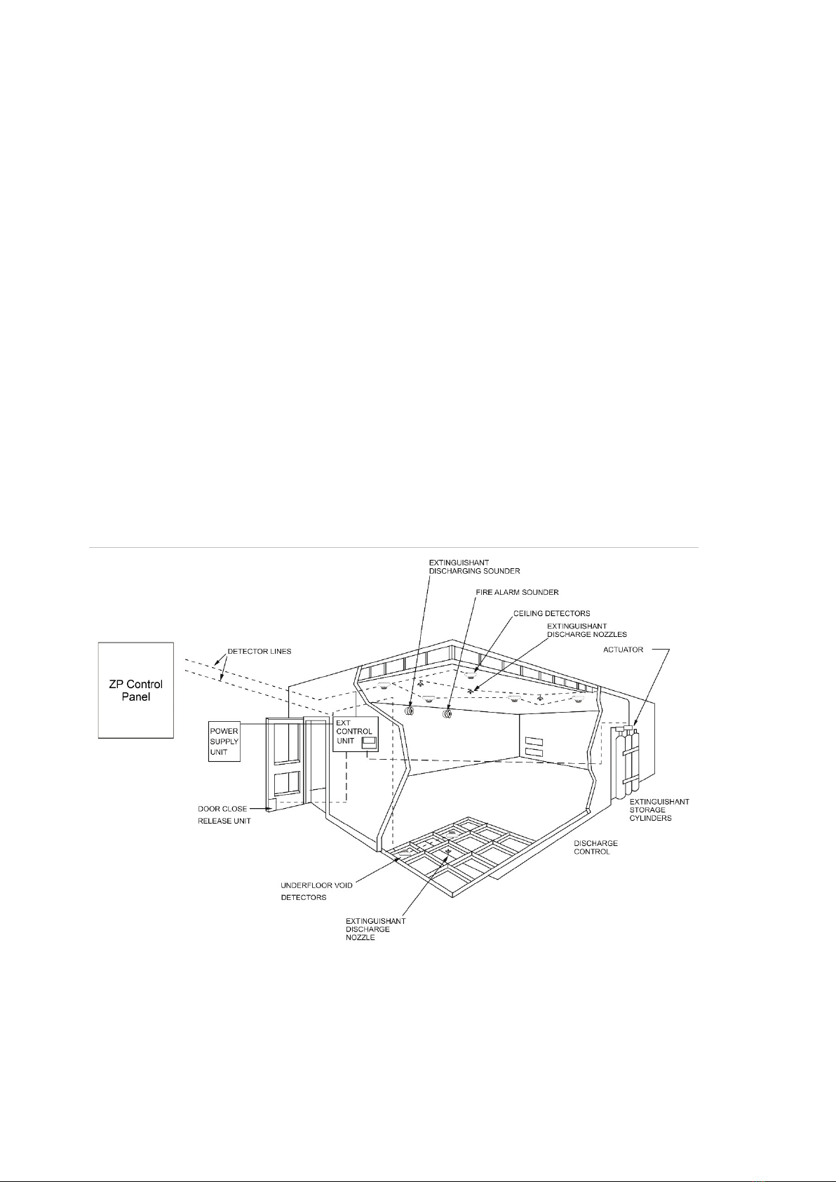
ZP3-ECU control unit overview
The ZP3-ECU Extinguishing Control Unit (Figure 2 on page 4) is designed to
connect to a Ziton addressable fire alarm detection system and control a fire
extinguishing system. It interfaces to the fire detectors of the fire detection
system and provides secure "coincidence connection" control of the
extinguishing system.
The self-contained unit has key switches for automatic or manual selection, as
well as lock-off for maintenance. Other controls are a manual extinguishant
release, an alarm silence button, extinguishant hold off button and indicators for
automatic, manual, locked-off, fault, fire, extinguishant discharged, and reset
status.
Outputs are provided for extinguishant release valves or actuators, audible fire
alarm sounders, separate extinguishant release sounders, visual exit signs, door
closing, and shutter release. Also provided are facilities for remote manual
extinguishant release, and remote operation and status functions.
Extensive monitoring is provided for many functions, including power supply,
fuses, and operation. Field wiring is monitored for extinguishant release
valves/actuators, fire sounder, extinguishant sounder, and manual extinguishant
release units.
Optional monitoring is provided for low extinguishant pressure, extinguishant
release verification, and locked/unlocked entry door status of the protected area.
The ECU is under the control of the fire alarm control panel. It communicates
with the fire alarm control panel every two seconds and reports the status of all
functions. A fault signal is raised at the fire alarm control panel for any out-of-
normal condition, which exists at the ECU. The fire alarm control panel indicates
the type of fault, and where applicable, reports the condition to a building
management system. Remote status of each ECU – automatic, manual, fault,
locked-off, or extinguishant discharged can be displayed at the fire alarm control
panel without additional wiring.
Each ECU operates one fire extinguishing system. Any number of ECUs may be
used, with each unit requiring two system addresses. The system is field
programmable, with functions such as detector cross-mapping, automatic
extinguishant release delay, selection of delay/no delay for manual extinguishant
release, and output relay control being fully configurable.