Zivid One+ S User manual

Zivid One+
User Guide
Zivid One+ S (ZVD1P-S)
Zivid One+ M (ZVD1P-M)
Zivid One+ L (ZVD1P-L)

Table of Contents
1 Start Guide 3
1.1 Zividboxcontents ................................... 3
1.2 TargetApplications .................................. 4
1.3 Robustness, Safety and IP rating . . . . . . . . . . . . . . . . . . . . . . . . . . 5
1.4 Connectivity and Power Supply . . . . . . . . . . . . . . . . . . . . . . . . . . . 5
1.5 SystemRequirements................................. 6
1.6 Mechanical and Electrical Installation . . . . . . . . . . . . . . . . . . . . . . . 7
1.7 ServiceandMaintenance............................... 11
1.8 Technical Specification Sheet . . . . . . . . . . . . . . . . . . . . . . . . . . . . 11
2 Zivid Studio 13
2.1 Introduction ....................................... 13
2.2 Toolbar.......................................... 13
2.3 AvailableViews..................................... 15
2.3.1 PointCloud................................... 15
2.3.2 Color....................................... 16
2.3.3 Depth ...................................... 16
2.4 ControlPanel ...................................... 17
2.4.1 Camera ..................................... 17
2.4.2 Capture ..................................... 18
2.5 QuickReferenceIndex................................. 23

help.zivid.com Start Guide
Start Guide
1.1 Zivid box contents
In the Zivid box you should find:
•Zivid 3D camera
•Power supply
•5 m USB 3.0 Cable (Machine Vision Certified)
Optional: 10 / 25 m optical cable.
0.9 - 4/20 3

help.zivid.com Start Guide
1.2 Target Applications
Zivid One+ 3D cameras are primarily targeted for industrial automation in the manufac-
turing, automotive, and logistic industries. Typical 3D machine vision applications for
industrial and collaborative robots are:
•Pick and place
•Machine tending
•Assembly
•Palletization
•Inspection
The cameras are factory calibrated. There is a one-to-one correspondence between color
and depth because Zivid cameras acquire XYZ point cloud data and RGB colors with
the same sensor chip. Zivid technology provides high-quality images of objects made
of materials with different optical properties, and of various shapes, dimensions, and
colors. Due to the high dynamic range, Zivid One+ cameras are suitable for imaging dark
absorptive parts and shiny metal parts. The following cases do not work well with Zivid
cameras:
•Transparent objects (e.g., plastic bottles)
•Highly specular surfaces (e.g., mirrors)
•Imaging for precision less than 0.03 mm
•Moving objects
Mounting can be stationary or on a robot.
0.9 - 4/20 4
help.zivid.com Start Guide
1.3 Robustness, Safety and IP rating
Robustness
Zivid One+ cameras have a robust aluminum casing. Cooling ribs are integrated into the
design in a way that makes Zivid look and stay cool!
Safety
Zivid One+ cameras are compliant with EN60950, FCC class A, CE, and CB environmental
standards.
Zivid One+ cameras use a white light source, which is tested against IEC62471 and is
classified as Risk Group 2.
Connections, assembly, and settings must be performed by competent technicians.
Do not connect external I/O signals to the device while it is powered; this may damage
the device.
IP rating
Zivid One+ cameras are water and dust resistant and are rated IP65. Zivid One+ cameras
can handle vibrations and shocks without being damaged according to the following
shock/vibration standards:
•5 G Random
•15 G Shock
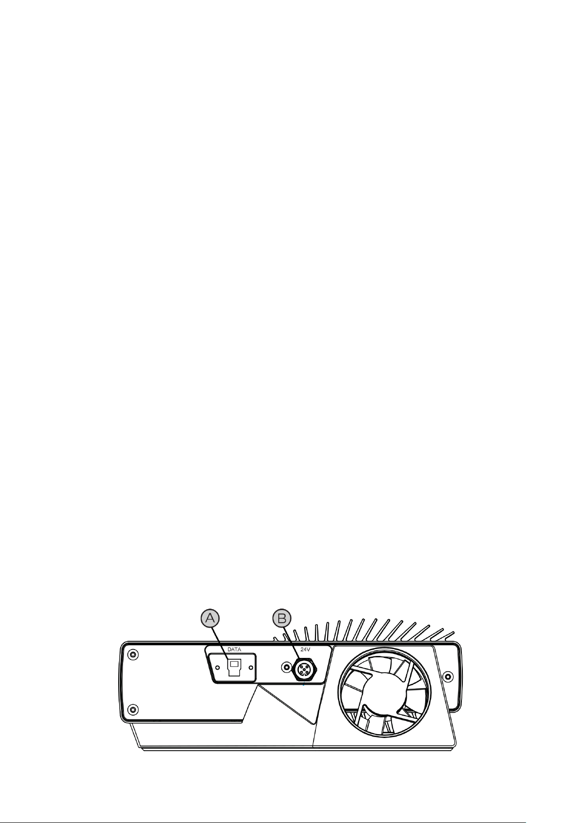
1.4 Connectivity and Power Supply
Available ports
A) USB3: Data SuperSpeed USB3 type-B receptacle for PC connection. Note: PC must
support USB 3.0 SuperSpeed. Cables need to be “USB3 Vision” compliant.
B) M12-5: Power Connector 24V, 5A DC
0.9 - 4/20 5

help.zivid.com Start Guide
Power supply interface
Exceeding the limit values may cause permanent damage. Please note the power ratings
if power is provided from other sources than the supplied AC/DC converter.
The Zivid unit is protected against reverse polarity and against overheating by a thermis-
tor that physically removes the power.
Pinout Pin Purpose
1 24V DC +/- 20% (Max 4A)
2 24V DC +/- 20% (Max 4A)
3 GND
4 GND
5 SENSE SIGNAL (optional)
Optional mating connector: TE Connectivity AMP 1838275-3 (Digikey: A97645-ND)
1.5 System Requirements
OS Windows 7/8/10 or Linux Ubuntu 16.04/18.04
GPU CPU with integrated GPU
This is the most cost-efficient and preferred solution for Zivid. The benefit
of an integrated GPU is that the copying of data from GPU to CPU is fast.
A high-end integrated GPU with 3GB of memory available is required for
optimal performance.
Recommendations:
•AMD Ryzen 5 2400G or better
•Intel i7 with HD630 or better
GPU Dedicated GPU
This solution may be best if the GPU is planned to be used for more than
Zivid computations. A medium to high-end AMD or NVIDIA GPU with 3GB
of memory is required for optimal performance.
Recommendations:
•NVIDIA GeForce GTX 1060 or better
•NVIDIA GeForce MX150 or better
•AMD Radeon RX 550 or better
USB SuperSpeed USB3 port
0.9 - 4/20 6

help.zivid.com Start Guide
1.6 Mechanical and Electrical Installation
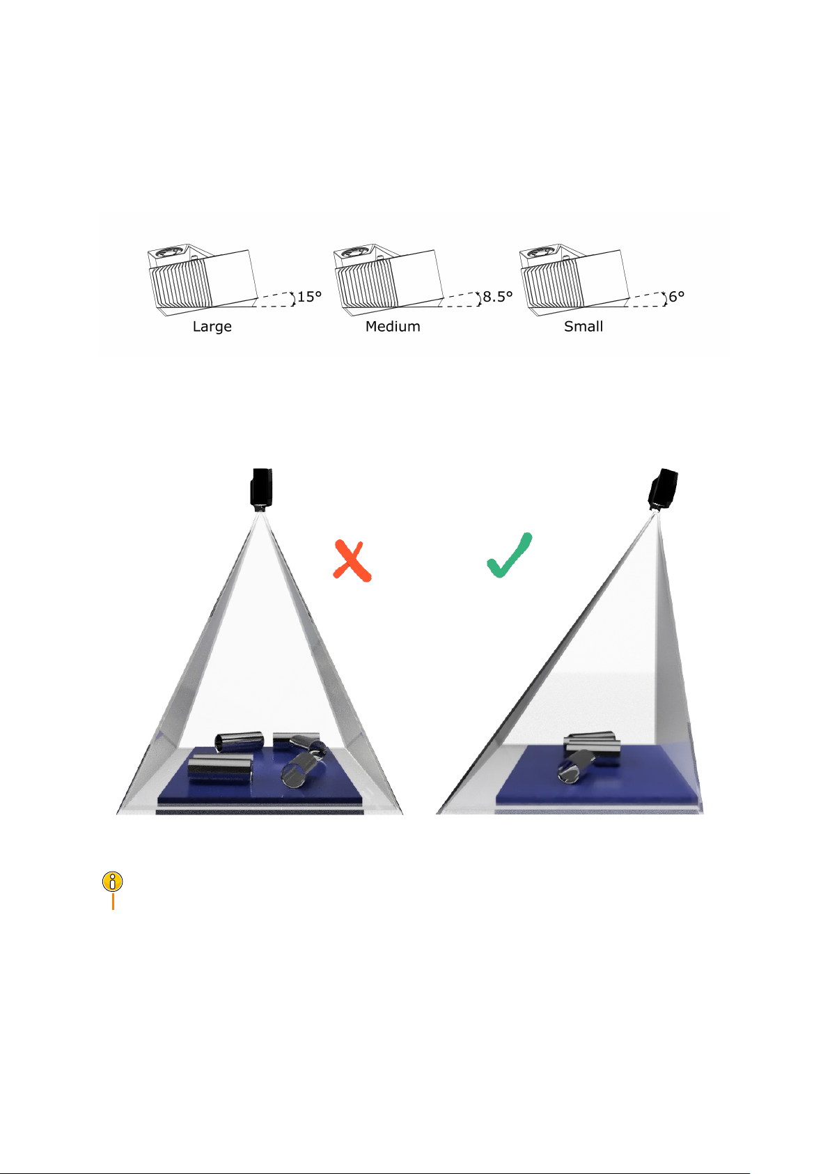
Working Distance and Field of View
0.9 - 4/20 7
help.zivid.com Start Guide
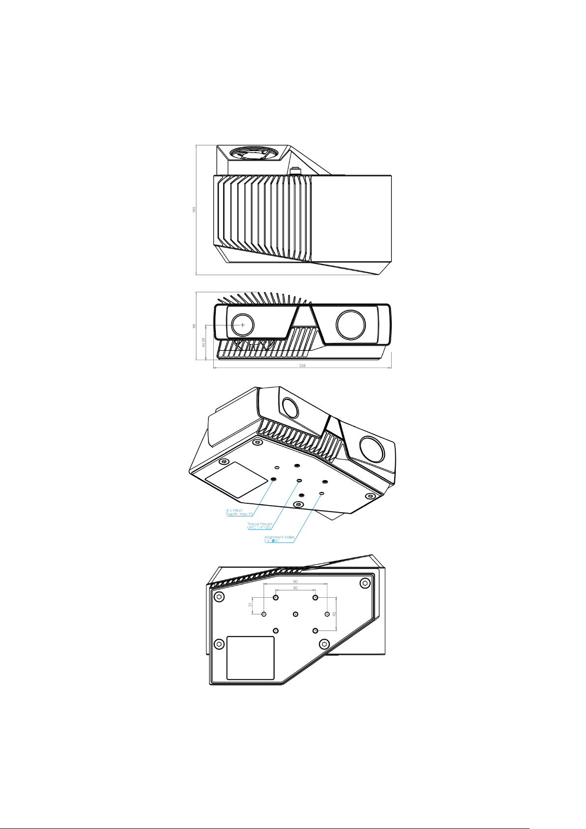
Mounting Specifications and Dimensions
Use the threaded holes on the bottom side of the device to mount it to a bracket. Zivid
cameras can be fixed on most standard photography tripods.
0.9 - 4/20 8
help.zivid.com Start Guide
Angle the camera
The imaging sensor inside Zivid cameras is offset at a slight pan angle in the azimuth
direction (y-axis). This should be considered if it is desired to have the camera perpen-
dicular to the scene.
Although the most intuitive, this is not the best way to mount the camera. If possible,
mount the camera at a slight tilt angle to avoid reflections from the background. This
also frees up space above the scene for easier access for tools and robots.
Camera tilting is more important if the scene contains specular surfaces.
Note
0.9 - 4/20 9
help.zivid.com Start Guide
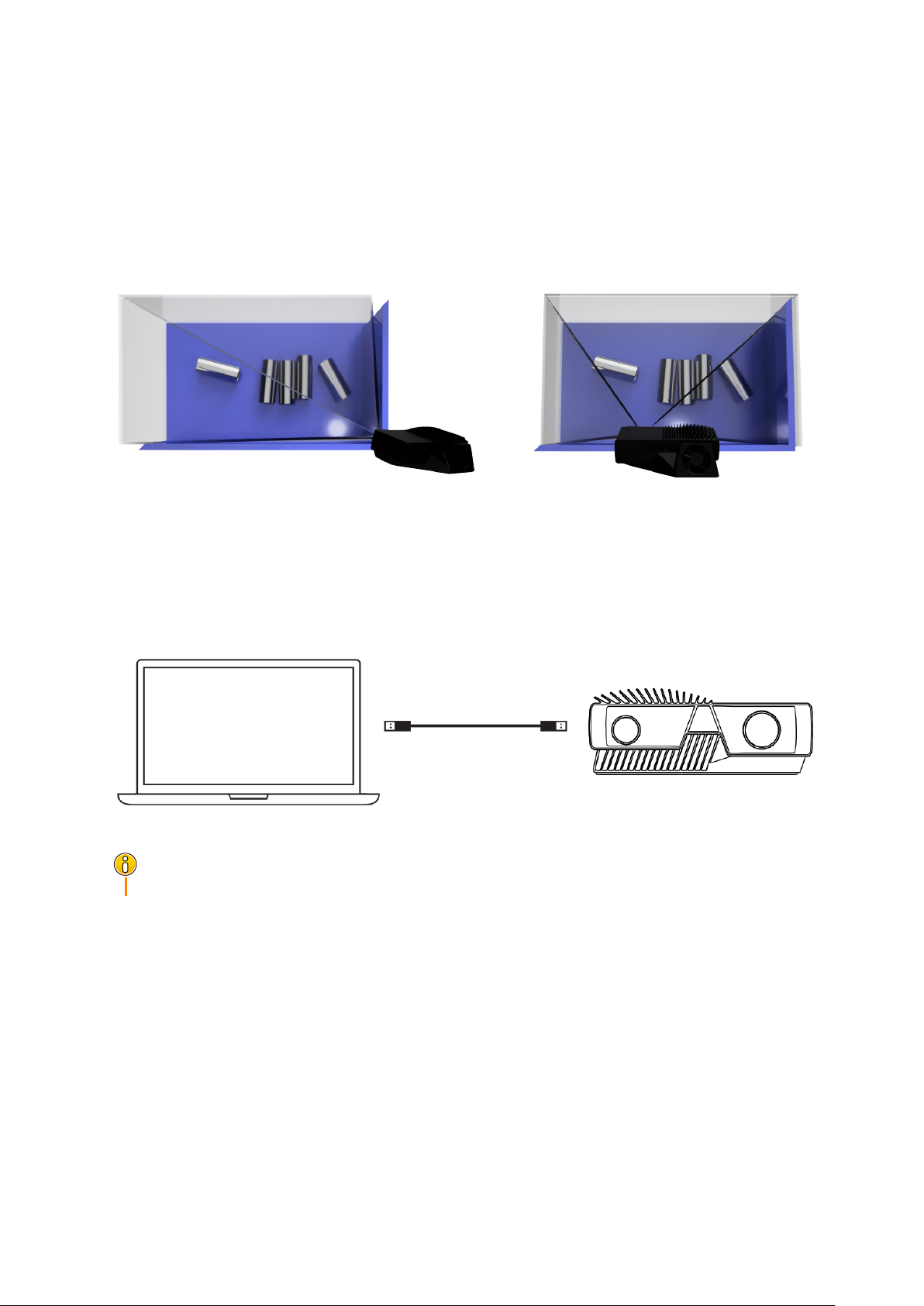
In bin-picking applications
For bin-picking applications, place the Zivid camera projector above the back edge or
above the rear corner of the bin (see images below). Pan and tilt it so that the 2D camera
is looking at the bin center. The projector rays should not fall on the inner surfaces of
the two walls closest to the projector; they should almost be parallel to those two walls.
Mounting the camera this way minimizes interreflections from the bin walls.
Connect the camera to a computer
1. Plug the power supply into the “24V” port and into a power outlet.
2. Plug the USB cable into the “DATA” port and into a USB 3.0 port on your PC.
Ensure that all connections are screwed tightly in.
Note
Using a direct cable from the PC to the Zivid camera works better than connecting the
camera via a USB hub.
Use only Zivid approved cables and extenders.
0.9 - 4/20 10
Other manuals for One+ S
1
This manual suits for next models
6
Table of contents
Other Zivid 3D Camera manuals

Popular 3D Camera manuals by other brands


KANDA
KANDA Obsidian S user guide

TeraBee
TeraBee TB-3DCAM-8060-USB user manual

SICK
SICK Ranger3 operating instructions

Radio Engineering Industries
Radio Engineering Industries SV-360HD Installation and configuration guide

Intel
Intel RealSense D400 Series user manual

Reality Technologies
Reality Technologies Madshot Usage manual