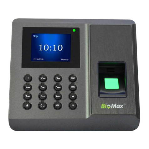
ZKaccess ProCapture-T User manual

Quick Start Guide
ProCapture-T & ProRF-T
+
ZKBioSecurity 3.0

.......................................................................................... .......................................................................................................................................................................................................................................................................................................................................................................................................................................
..........................................................................................
1
ProCapture-T & ProRF-T and ZKBioSecurity 3.0 Quick Start Guide
CONTENT
Safety Precautions....................................................................2
On Using Face Recognition Device............................3
Device Overview ......................................................................5
Product Dimensions & Installation..............................7
Power Connection ..................................................................8
Ethernet Connection.............................................................9
RS485 Connection................................................................10
Lock Relay Connection .....................................................11
Wiegand Output Connection......................................13
Standalone Installation .....................................................14
Device Operation..................................................................15
ZKBioSecurity
Software
Installation and
Setup starts at
Page 18

2
ProCapture-T & ProRF-T and ZKBioSecurity 3.0 Quick Start Guide
Safety Precautions
The following precautions are to keep users safe and prevent any damage.
Please read carefully before installation.
Do not install the device in a place subject to direct sunlight,
humidity, dust or soot.
Do not place a magnet near the product. Magnetic objects
such as magnets, CRTs, TVs, monitors or speakers may dam-
age the device.
Do not place the device next to heating equipment.
Be careful not to let liquid like water, drinks or chemicals
leak inside the device.
Do not let children touch the device without supervision.
Do not drop or damage the device.
Do not disassemble, repair or alter the device.
Do not use the device for any other purpose than specied.
Clean the device often to remove dust on it. In cleaning, do
not splash water on the device but clean it with a smooth
cloth or towel.
Contact your supplier in case of a problem.

3
ProCapture-T & ProRF-T and ZKBioSecurity 3.0 Quick Start Guide
On Using Face Recognition Device
1. Recommended Standing Position
For user heights between 1.5m to 1.8m, it is
recommended to install the device at 1.15m above
ground (may be modied according to user
average height).
a. Recommended Registration and Verication Position
b. Factors Aecting the Preciseness of Verication
Non-identical registration Non-identical registration
and verication gestures and verication height
During registration and verication pro-
cedures, the position of device should
not be changed to prevent deduction in
verication preciseness. If it is necessary
to move the device, its vertical height
should not be changed.

4
ProCapture-T & ProRF-T and ZKBioSecurity 3.0 Quick Start Guide
Non-identical registration Non-identical registration
and verication distances from device and verication distances from device
2. Registration
a. During registration, it is required to adjust your upper body to t your eyes into the
green frame on the screen.
b. During verication, it is required to show your face in the center of the screen and
t your face into the green frame in the screen.
On Using Face Recognition Device

5
ProCapture-T & ProRF-T and ZKBioSecurity 3.0 Quick Start Guide
Device Overview
Not all products have ngerprint or card function.
ProCapture-T ProRF-T
ProCapture-T
Camera
2.4 inch Color Screen
Touch Keypad
Door Bell & LED Indicator
Fingerprint & Card Reader
Card Reader Area Area
USB Slot
Reset Button
ProRF-T
Left side & bottom view is common for both the devices
Security Screw Holes
(for securing the device onto
the back plate)
Speaker

6
ProCapture-T & ProRF-T and ZKBioSecurity 3.0 Quick Start Guide
Device Overview
7 pin Cable connectors
8 pin Cable connectors
4 pin Cable connectors
2 pin Cable connectors
12pin Cable connectors
Tamper alarm button
?
Beep, LED
?
Wiegand In
?
Power Out
?
RS485
?
RS232
?
Wiegand Out
?
Power In
?
Alarm
?
Lock
?
Exit Button
?
?
Doorbell
Door Sensor
?
Auxiliary In
RLED
RJ45-1
COM1
+12V
BUT
BELL+
BELL-
RJ45-3
GLED
AL-
IWD0
NO1
GND
RJ45-2
IWD1
NC1
GND
SEN
RJ45-6
BEEP
AL+
Ethernet
Alarm
Wiegand
Wiegand
RS485
Lock
Bell
Power
Sensor
Button
RXD
GND
WD1
TXD
485A
GND
485B
WD0
+12V
GND
GND
AUX
Auxilliary
RS232
Power In
}
}
}
}
}
}
}
}
}
}
}
Beep
Green LED
Red LED
}
RLED
RJ45-1
COM1
+12V
BUT
BELL+
BELL-
RJ45-3
GLED
AL-
IWD0
NO1
GND
RJ45-2
IWD1
NC1
GND
SEN
RJ45-6
BEEP
AL+
Ethernet
Alarm
Wiegand
Wiegand
RS485
Lock
Bell
Power
Sensor
Button
RXD
GND
WD1
TXD
485A
GND
485B
WD0
+12V
GND
GND
AUX
Auxiliary
RS232
PowerIn
}
}
}
}
}
}
}
}
}
}
}
}
Beep
GreenLED
Red LED
}
In
Out In
Output
}
In
Output
Out In

7
ProCapture-T & ProRF-T and ZKBioSecurity 3.0 Quick Start Guide
Product Dimensions & Installation
Product Dimensions
Mounting the Device on the Wall
3.0in
(76.1mm)
1.38in
(35mm)
7.34in
(186.5mm)
3.43in
(87mm)
7.70in
(195.5mm)
ProCapture-T
0.51in
(13mm)
1
2
ProCap ture-T
Fix the back plate onto the wall using wall
mounting screws.
Note: We recommend drilling the mounting
plate screws into solid wood (i.e. stud/beam).
If a stud/beam cannot be found, use supplied
drywall plastic anchors.
Use security screws to fasten
the device to back plate.
Insert the device to back plate.

8
ProCapture-T & ProRF-T and ZKBioSecurity 3.0 Quick Start Guide
Power Connection
Without UPS
With UPS (Optional)
Recommended Power Supply
• 12V±10%, at least 500mA
• To share the power with other devices, use a power supply with higher current
ratings.
12V DC Adaptor
12V DC Adaptor
GND
12V DC
1
2
GND
12V DC
1
2
RLED
RJ45-1
COM1
+12V
BUT
BELL+
BELL-
RJ45-3
GLED
AL-
IWD0
NO1
GND
RJ45-2
IWD1
NC1
GND
SEN
RJ45-6
BEEP
AL+
Ethernet
Alarm
WiegandIn
Output
WiegandOutput
RS485
Lock Bell
PowerOut
Sensor
Button
RXD
GND
WD1
TXD
485A
GND
485B
WD0
+12V
GND
GND
AUX
AuxiliaryIn
RS232
PowerIn
}
}
}
}
}
}
}
}
}
}
}
}
}
}
RLED
RJ45-1
COM1
+12V
BUT
BELL+
BELL-
RJ45-3
GLED
AL-
IWD0
NO1
GND
RJ45-2
IWD1
NC1
GND
SEN
RJ45-6
BEEP
AL+
Ethernet
Alarm
WiegandIn
Output
WiegandOutput
RS485
Lock Bell
PowerOut
Sensor
Button
RXD
GND
WD1
TXD
485A
GND
485B
WD0
+12V
GND
GND
AUX
AuxiliaryIn
RS232
PowerIn
}
}
}
}
}
}
}
}
}
}
}
}
}
}

9
ProCapture-T & ProRF-T and ZKBioSecurity 3.0 Quick Start Guide
Ethernet Connection
LAN Connection
RLED
RJ45-1
COM1
+12V
BUT
BELL+
BELL-
RJ45-3
GLED
AL-
IWD0
NO1
GND
RJ45-2
IWD1
NC1
GND
SEN
RJ45-6
BEEP
AL+
Ethernet
Alarm
WiegandIn
Output
WiegandOutput
RS485
Lock Bell
PowerOut
Sensor
Button
RXD
GND
WD1
TXD
485A
GND
485B
WD0
+12V
GND
GND
AUX
AuxiliaryIn
RS232
PowerIn
}
}
}
}
}
}
}
}
}
}
}
}
}
}
RJ 45
1
2
3
4
5
6
7
8
RJ45-6
Yellow
RJ45-3
Green
RJ45-2
RJ45-1
Black
Red
DESCRIPTION WIRE
ZKBioSecurity
Ethernet cable
Network Cable Apator

10
ProCapture-T & ProRF-T and ZKBioSecurity 3.0 Quick Start Guide
RS485 Connection
RS485 Fingerprint Reader Connection
Dip Settings
1. There are six DIP switches on the back of RS485 ngerprint reader, switches 1-4 are for
RS485 address, switch 5 is reserved, switch 6 is for reducing noise on long RS485 cable.
2. If RS485 ngerprint reader is powered from the terminal, the length of wire should be less
than 100 meters or 330 ft.
3. If the cable length is more than 200 meters or 600 ft, the number 6 switch should be ON
as below.
RLED
RJ45-1
COM1
+12V
BUT
BELL+
BELL-
RJ45-3
GLED
AL-
IWD0
NO1
GND
RJ45-2
IWD1
NC1
GND
SEN
RJ45-6
BEEP
AL+
Ethernet
Alarm
WiegandIn
Output
WiegandOutput
RS485
Lock Bell
PowerOut
Sensor
Button
RXD
GND
WD1
TXD
485A
GND
485B
WD0
+12V
GND
GND
AUX
AuxiliaryIn
RS232
PowerIn
}
}
}
}
}
}
}
}
}
}
}
}
}
}
Do not use
+12V Red
GND Black
IWD1
IWD0
BEEP Purple
GLED Gray
RLED Blue
1
7
1
8
DESCRIPTION WIRE
Green
White
1
WD0 Green
2
WD1 White
3GND Black
4
Gray
5
6GND Black
7
8
485B Yellow
485A Blue
Purple
PIN DESCRIPTION WIRE
TXD
RXD
123456
ON
123456
ON
Distance: More than 200 meters

11
ProCapture-T & ProRF-T and ZKBioSecurity 3.0 Quick Start Guide
Lock Relay Connection
Device Not Sharing Power with the Lock
Notes:
1. The system supports NO LOCK and NC LOCK. For example the NO LOCK (normally opened
at power on) is connected with ‘NO1’ and ‘COM1’ terminals, and the NC LOCK (normally
closed at power on) is connected with ‘NC1’and ‘COM1’ terminals.
2. When electrical lock is connected to the Access Control System, you must parallel one
FR107 diode (equipped in the package) to prevent the self-inductance EMF from aecting
the system.
Do not reverse the polarities.
RLED
RJ45-1
COM1
+12V
BUT
BELL+
BELL-
RJ45-3
GLED
AL-
IWD0
NO1
GND
RJ45-2
IWD1
NC1
GND
SEN
RJ45-6
BEEP
AL+
Ethernet
Alarm
WiegandIn
Output
WiegandOutput
RS485
Lock Bell
PowerOut
Sensor
Button
RXD
GND
WD1
TXD
485A
GND
485B
WD0
+12V
GND
GND
AUX
AuxiliaryIn
RS232
PowerIn
}
}
}
}
}
}
}
}
}
}
}
}
}
}
GND
NC1
12V DC
Normally Closed Lock
12V DC Adaptor
GND
FR107
Diode
-
+
COM1
1
12
Do not use
White
Blue
Yellow
Orange
Green
Purple
Brown
Red
Black
Gray
Black
Red
DESCRIPTION WIRE
AL+
NC1
COM1
NO1
BUT
GND
SEN
BELL+
BELL-
GND
AUX
AL-
Sensor
GND

12
ProCapture-T & ProRF-T and ZKBioSecurity 3.0 Quick Start Guide
Lock Relay Connection
COM1
FR107
Diode
GND
NC1
Normally Closed Lock
+12V
1
7
1
12
White
Blue
Yellow
Orange
Green
Purple
Brown
Red
Black
Gray
Black
Red
Do not use
DESCRIPTION WIRE
AL+
NC1
COM1
NO1
BUT
GND
SEN
BELL+
BELL-
GND
AUX
AL-
-
+
Sensor
GND
RLED
RJ45-1
COM1
+12V
BUT
BELL+
BELL-
RJ45-3
GLED
AL-
IWD0
NO1
GND
RJ45-2
IWD1
NC1
GND
SEN
RJ45-6
BEEP
AL+
Ethernet
Alarm
WiegandIn
Output
WiegandOutput
RS485
LOCK Bell
PowerOut
Sensor
Button
RXD
GND
WD1
TXD
485A
GND
485B
WD0
+12V
GND
GND
AUX
AuxiliaryIn
RS232
PowerIn
}
}
}
}
}
}
}
}
}
}
}
}
}
}
Device Sharing Power with the Lock

13
ProCapture-T & ProRF-T and ZKBioSecurity 3.0 Quick Start Guide
Wiegand Output Connection
RLED
RJ45-1
COM1
+12V
BUT
BELL+
BELL-
RJ45-3
GLED
AL-
IWD0
NO1
GND
RJ45-2
IWD1
NC1
GND
SEN
RJ45-6
BEEP
AL+
Ethernet
Alarm
WiegandIn
Output
WiegandOutput
RS485
Lock Bell
PowerOut
Sensor
Button
RXD
GND
WD1
TXD
485A
GND
485B
WD0
+12V
GND
GND
AUX
AuxiliaryIn
RS232
PowerIn
}
}
}
}
}
}
}
}
}
}
}
}
}
}

14
ProCapture-T & ProRF-T and ZKBioSecurity 3.0 Quick Start Guide
Standalone Installation
Sensor
Lock
ALARM
EXIT
No Touch
Exit Button
Doorbell
ProCapture-T
Ethernet
ZKBioSecurity
ZKBioSecurity
Rs485 Fingerprint
Reader

15
ProCapture-T & ProRF-T and ZKBioSecurity 3.0 Quick Start Guide
Device Operation
Date/Time Settings
Press icon to enter the Main Menu > System > Date Time to set date and time.
Adding User
Press icon to enter the Main Menu > User Mgt. > New User to enter the New User adding interface.
Settings include entering user ID, user role, choosing user role (Super Admin / Normal User), registering
ngerprint / badge number / password, taking user photo , and setting access control role.
Ethernet Settings
Press icon to enter the Main Menu > Comm. > Ethernet.
The parameters below are the system default values. Please adjust them according to the actual network.
IP Address: 192.168.1.201
Subnet Mask:255.255.255.0
Gateway: 0.0.0.0
DNS: 0.0.0.0
TCP COMM. Port: 4370
DHCP: Dynamic Host Conguration Protocol, which dynamically allocate IP addresses for clients via
server. If DHCP is enabled, IP cannot be set manually.
Display in Status Bar: To set whether to display the network icon on the status bar of initial interface.
Not all products have this function, the real product shall prevail.

16
ProCapture-T & ProRF-T and ZKBioSecurity 3.0 Quick Start Guide
Device Operation
ADMS Settings
Press icon to enter the Main Menu > Comm. > ADMS, to set the parameters which are used for connecting
with the ADMS server.
When the Webserver is connected successfully, the initial interface will display the logo.
Server Address: Enter IP address of the ADMS server (namely, the IP address of server where the software
is installed).
Server Port: Enter the port number used by the ADMS server.
Enable Proxy Server: Method of enabling proxy. To enable proxy, please set the IP address and port
number of the proxy server. Entering proxy IP and server address will be the same.
Note: To connect the device to ZKBioSecurity software, Ethernet and ADMS options must be set correctly.
Access Control Settings
Press icon to enter the Main Menu, press and to select Access Control.
To gain access, the registered user must meet the following conditions:
1. User’s access time must fall within either user’s personal time zone or group time zone.
2. User’s group must be in the access combo (when there are other groups in the same access combo,
verication of members of those groups are also required to unlock the door).
Access Control Options: To set parameters of the lock and other related devices.
Time Rule Setting: To set a maximum of 50 time rules. Each time rule consists of 10 spaces (7 spaces for
one week and 3 holiday spaces), each space consists of 3 time periods.
Holidays: To set dates of holiday and the access control time zone for that holiday.
Combined Verication: To set access control combinations. A combination consists of a maximum of 5
access control groups.
Anti-Passback Setup: To prevent passing back which causes risks to security. Once this function is en-
abled, entry and exit records must be matched in order to open door. In Anti-Passback, Out Anti-Passback
and In/Out Anti-Passback functions are available.

17
ProCapture-T & ProRF-T and ZKBioSecurity 3.0 Quick Start Guide
Device Opreation
Access Control Combination Settings
E.g. : Add an access control combination which requires 2 person’s verication from both Access Control
Group 1 (set in User Management) and Access Control Group 2.
Note:
A. A single access control combination can consist of a maximum of 5 access control groups (in order
to open door, verication of all 5 users is required).
B. If the combination is set as shown in gure 3, a user from access control group 2 must obtain veri-
cation of 2 users from access control group 1 in order to open door.
C. Set all access control group number to zero to reset access control combination.
Troubleshooting
1. Fingerprint cannot be read or it takes too long ?
@Check whether a nger or ngerprint sensor is stained with sweat, water or dust.
@Retry after wiping o nger and ngerprint sensor with dry paper tissue or a mildly wet cloth.
@If a ngerprint is too dry, blow on the nger and retry.
2. “Invalid time zone” is displayed after verication?
@Contact Administrator to check if the user has the privilege to gain access within that time zone.
3. The Tamper Alarm rings?
@Check whether the user privilege is set correctly.
@Check whether the lock wiring is correct.
@Check whether anti-passback mode is in use. In anti-passback mode, only the person who has
entered through that door can exit.
4. The Tamper Alarm rings?
@To cancel the triggered alarm mode, carefully check whether the device and back plate are se-
curely connected to each other, and reinstall the device properly if necessary.
5. How to cancel alarms?
@Verify a registered user.
1. In “Access Control” interface, press to select
“Combined Verification”; then press to enter
the “Combined Verification” list. Click the desired
combination and press to enter the modifica-
tion interface (as shown in figure 2).
2. Click or to change the number, click or
to switch editing box, set the user group num-
ber, and click to save and return to“Combined
Verification”list (as shown in figure 3).

18
ProCapture-T & ProRF-T and ZKBioSecurity 3.0 Quick Start Guide
ZKBioSecurity 3.0
Installation & Setup
It is recommended to install software version 3.0.3.0 or above
Downloading...........................................................................19
Installation ..................................................................................20
Adding Device.........................................................................22
Creating a Time Zone.........................................................24
Creating an Access Level.................................................25
Enrolling Personnel..............................................................26
Wiegand Format....................................................................28
Add & Delete Personnel to Access Level .............29
Real -Time Monitoring.......................................................30
Exporting Reports.................................................................31

19
ProCapture-T & ProRF-T and ZKBioSecurity 3.0 Quick Start Guide
Downloading
1. Go to http://www.zkteco.com/product/ZKBioSecurity3.0_421.html
2. Download the latest software and related les as required.
3. Once downloaded, extract the .rar le to a new folder.
4. Click on setup to
begin installstion.
This manual suits for next models
1
Table of contents
Other ZKaccess IP Access Controllers manuals