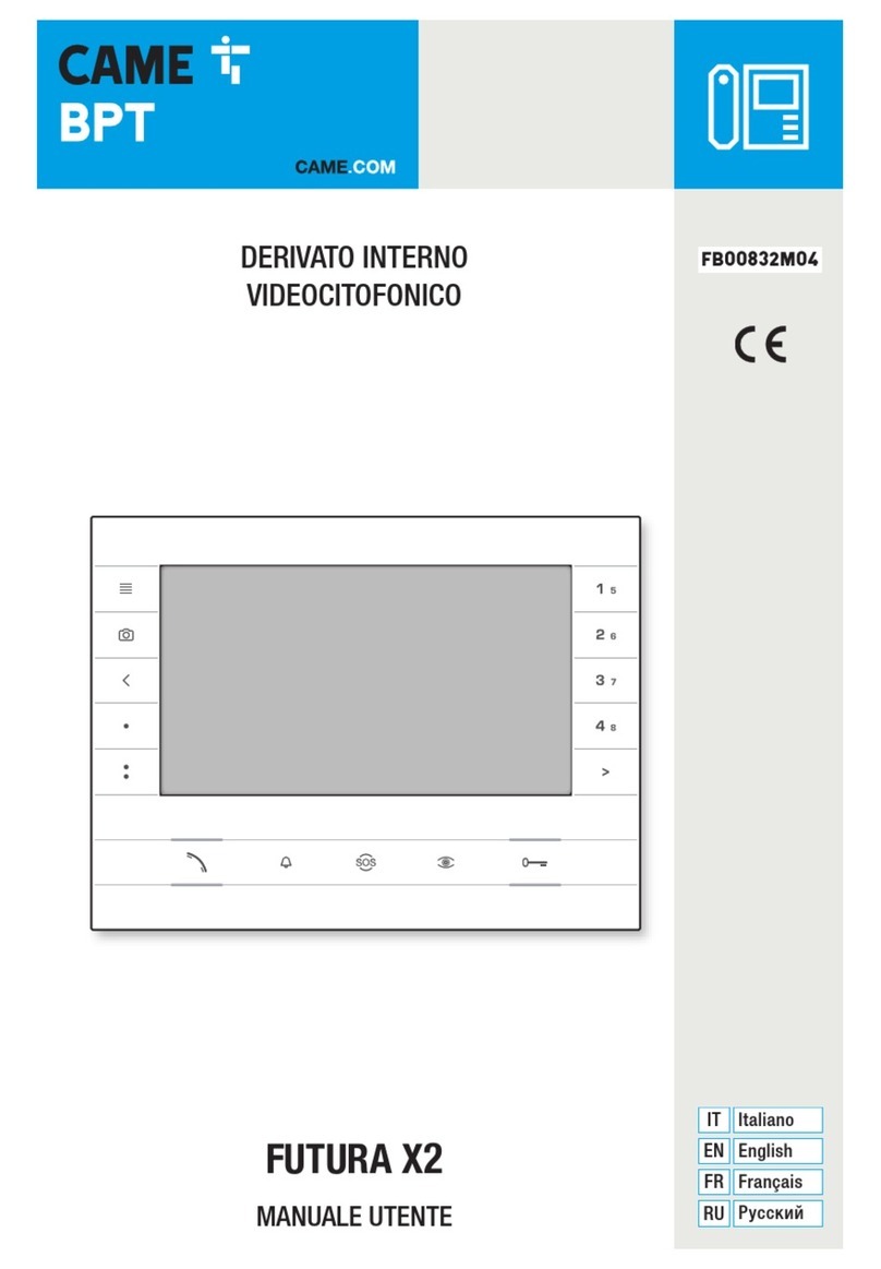
ZKTeco VT07-B22L User manual

User Manual
VEX-B21L
USER MANUAL
VT07-B22L
April, 2023

Remark
Please follow the user manual for correct installation and testing. If
there is any doubt please call our tech-supporting and customer center.
Our company applies ourselves to reformation and innovation of our
products. No extra notice for any change. The illustration shown here
is only for reference. If there is any difference, please take the actual
product as the standard.
The product and batteries must be handled separately from household
waste. When the product reaches the end of service life and needs to
be discarded, please contact the local administrative department and put
it in the designated collection points in order to avoid the damage to the
environment and human health caused by any disposal. We encourage
recycling and reusing the material resources.

Product Features.......................................................1
Technical Parameters................................................1
Pictures......................................................................2
Operations .................................................................7
1. Security..................................................................8
2. Smart....................................................................14
3. Intercom...............................................................17
4. Message...............................................................20
5. Setup....................................................................20
Web Settings ...........................................................23
System Configuration.............................................25
System Diagram......................................................29
Installation ...............................................................31
Troubleshooting......................................................34
Safety Instructions..................................................35
CATALOG

Product Features
1.
Building intercom application:
Talkback: Support video call, monitoring, unlocking, and checking the call
records.
Security: Support 8 alarm zones with 3 states, zone and scene setup.
Smart: Support smart home extension by RS485 communication(Optional).
2.
Operating system: Linux
Technical Parameters
Voltage: DC 12V
POE(VT07-B22L/VT07-B23L/VT10-B21L)
Rated power: 9W
12W(VT7-B22L, Switch (with Dual RJ45
Ports) )
Standby power consumption: 1.5W
3.0W(VT7-B22L, Switch (with Dual RJ45
Ports) )
Display screen: 7''/10.1''
Touch screen: Capacitive / Resistive touch screen
Resolution:
7'': 800x480
10.1'': 1024x600
Operating temperature: -10℃~+55℃
Storage temperature: -10℃~+60℃
Storage Relative humidity: 20%~85% IP
grade: IP30

Pictures
Model
:
VT10-B21L
Speaker
10.1'' capacitive
touch screen
Microphone
Model
:
VT07-C23L
7'' capacitive
touch screen
Speaker
Handsfree
Reserved
Calling management
center
Monitoring
Unlocking
Microphone

Model:
VT07-C22L
7'' capacitive
touch screen
Speaker
Microphone
◇Indoor monitor doesn’t support the connection with external camera, audio
extension, WIFI, Bluetooth, external USB and TF storage card.
◇Standard indoor monitor doesn’t include RS485 communication function.
Please contact the supplier if you have such requirement.
-5-

Operations
Main menu: Dial, Panel, Message, Security, Concierge, Monitor, Setup.
Instructions of status bar and shortcut key:
1.
Call logs: Click to check call logs.
2.
Phone Book: Click to check and call contacts.
3.
SOS: Click to make a direct emergency call to Master Station.
4.
Lift control: Click to summon the elevator to go up or down. Click
Permit inside of it to release the floor button in the elevator.
5.
QR code: Click to scan QR code with Smart Life app to add this Indoor
Monitor to your phone.
6.
Mute: Click to mute.
7.
Turn off: Click to turn off the screen.
-

1.
Dial
Click “Dial” icon, the system will enter the following interface:
1.1
Call Resident
Input 1-3 digits building No.+ “Building” + 2-digit Unit No. + “Riser”
+4-digit room No., then click
icon to call.
The system will enter into the following interface:
When the call is answered, the system will enter into call state:
1.
If there is a camera, the caller’s image will be displayed on the screen;
2.
When the call is answered, the video will be uploaded into the
indoor monitor.
When calling, the indoor monitor will ring; if there is no answer
within 25 seconds, the call will be ended.
click
icon to end the call.
-

1.2
Call Master Station
Click “ ” icon to call master station, the system will call master station
No.1-No.5 successively. If the master station cannot be searched or call
failed, the system will automatically call next master station. When the
master station answers, it will ring and stop calling next one.
Click
icon to end the communication.
1.3
Receive Call from Door Station
When the door station, wall door station or secondary door station calls,
the indoor monitor will ring; when door station calls indoor monitor, the
image from door station will be displayed on the indoor monitor; if there
is no answer within 25 seconds, the call will be ended.
click
icon to end the call; click
icon to unlock the door.
Remark: Click
icon to switch between answering interface and
monitoring interface of IP camera. After numeric keypad shows, press
number key "2" to "9" to select the IP camera and press "1" to return to
previous page.
2.
Panel
Click “Panel” icon on the main interface, the system will enter the
following interface:
-

The door station can be monitored here. To switch the type of door station,
please follow the operations as below:
1.
Click ” icon to select the type of door station Click ”icon Click
“
” to start monitoring;
2.
Click ”icon Click “ ” icon to select the type of door stationClick
“
” to start monitoring.
During monitoring, click “ ” icon to unlock the door.
Remark: The system’s default monitoring time is 25s.
3.
Message
Click “Message” icon on the main interface, the system will enter the
following interface:
-

Note: Indoor monitor can only receive the message sent by the
management software installed on the computer which is usually located
at guard center.
Up to 64 records can be received in SMS.
4.
Security
Click “Security” icon on the main interface, the system will enter the
following interface:
4.1
ON/OFF
Click “ON/OFF” icon, the system will enter into the following interface:
-

4.1.1
ON
Click “Out”, “Home”, or “Sleep” icon to activate the alarm sensors,
the icon on the main interface will light up with a beep and stay lit.
4.1.2
OFF
(1)
During delay time of the alarm, click “OFF” icon, the system will
beep to disable the alarm.
(2)
Input user password(the default password is 1234) to disable the
alarm under alarm ON status.
4.2
Zone
Remark: the settings should be made when alarm is OFF.
Click “Zone” icon and input 1-16 digits password(the default password
is 1234), the system will enter into the following interface:
4.2.1
Alarm Type
Click Type, it will show as the following. In this interface, you can set
alarm Type as: Normal, Emerg. or 24 Hour. 24 Hour and Emergency types
are always active.

4.2.2
Mode
Click Mode, it will show the following interface. In this interface, you
can set mode as: 3C, NO, NC or BELL.
4.2.3
Delay Time
It refers to the delay time of giving an alarm. Click Delay setting, it
will show the following interface with selections: 0s, 5s, 15s, 20s, 25s,
40s or 60s as the desired delay time. For example, select the delay
time: 5s. Once the alarm sensor is triggered, the indoor monitor will
issue the sirens after 5 seconds.
4.2.4
Sensor Type
Click sensor type, it will show the following interface. Each sensor
type can be set up as: Smoke, Gas, PIR, Door, Window, Panic, Flood.

4.3
Scene
Click “Scene” icon, the system will enter into the following interface:
refers to Alarm ON, refers to Alarm OFF. To set the sensor of alarm
stations, you can click the corresponding station with
icon. Click
"
Activation Time
"
to select the corresponding time. The options of
activation time include NONE, 30s, 40s, 60s, 100s and 300s.
4.4
Setup
Click “Setup” icon, the system will enter into the following interface:

You can set the new system password with 1-16 digits (the default
password is 123456). System password is used for system settings.
5.
Concierge
Click “Concierge” icon on the main interface, the system will enter
the following interface:
Click “
” icon to call master station, the system will call master station
No.1-No.5 successively. If the master station cannot be searched or call
failed, the system will automatically call next master station. When the
master station answers, it will ring and stop calling next one.
Click
icon to end the communication.

6.
Monitor
Click “Monitor” icon on the main interface, the system will enter the
following interface:
The IP camera can be monitored here. To switch the type of IP
camera, please follow the operations as below:
1.
Click ” icon to select the camera Click ”icon Click “ ” to
start monitoring;
2.
Click ”icon Click “ ” icon to select the camera Click “ ” to
start monitoring.
Remark: The system’s default monitoring time is 25s.
7.
Setup
Click “Setup” icon on the main interface to make the following settings.
7.1
Display
“Dark Mode”, “Brightness” and “Sleep Time” can be set
.

7.2
Sounds
Click “Sounds” icon, the system will enter into the following interface:
“Auto Answer”, “Ring Vol”, “Intercom Vol” and
"
Ringtone" can be set.
7.3
Date & Time
Click “Date & Time” icon, the system will enter into the following interface:
This interface can set “Auto”, “Date”, “Time Zone”, “12H/24H”, “Date
Format” and “NTP”.
7.4
Language
Click “Language” icon, the system will enter into the following interface:

The system language can be switched.
7.5
Devices
Click “Devices” icon, the system will enter into the following interface:
The device information can be viewed.
7.6
Version
Click “Version” icon, the system will enter into the following interface:

Version information includnig “FW”, “UI”, “LAN IP”, “WiFi IP” and “MAC”
can be viewed.
7.7
More
Click “More” icon, then input 1-16 digits password (the default password
is 123456 ) to make the following settings:
7.7.1
Network
Click “Network” icon, the system will enter into the following interface:
After using the DHCP, the router will automatically distribute IP
address. Other settings are the same as the ones of Smart Life APP.
IP: Static IP address.

Mask: The default Mask address is 255.255.255.0. Normally, it can keep
unchanged. To modify it, click the setting box twice, a keypad will pop
up for entering new Mask address.
Gateway: The Gateway in one system must be in the same segment.
DNS: It refers to name resolution address (DNS of local operator). If the
indoor monitor is used in external network, the address must be
completed correctly; if it is used in internal network, the address can be
ignored.
7.7.2
Room
Click “Room” icon, the system will enter into the following interface:
Warning: Please revise Sync No.(6 digits) as soon as possible after you
read the user manual. The Sync No. of all indoor monitors in one
household must be the same.
Input the 3-digit Building No. such as 001, and then click “OK” to
finish the building No. setting.
The setting method of Riser No., Apartment No., Device No., CMS IP and
Sync No. is the same as the one of Building No.. When Device No. is set
to be 0, the indoor monitor is regarded as the main; when Device No. is
set from 1 to 5, the monitor is regarded as the sub1 to sub5.
This manual suits for next models
3
Table of contents
Other ZKTeco Intercom System manuals
ZKTeco
ZKTeco VE01-B22L User manual

ZKTeco
ZKTeco SpeedFace-V3L User manual

ZKTeco
ZKTeco Aura12 User manual
ZKTeco
ZKTeco FaceDepot-7BL User manual
ZKTeco
ZKTeco FaceDepot 4A User manual

ZKTeco
ZKTeco MULTIUNITIES VE02-03-04-06-08-10-12-A01 User manual

ZKTeco
ZKTeco PA22 User manual
ZKTeco
ZKTeco VDPO3-B3 User manual
ZKTeco
ZKTeco SpeedFace-V3L User manual
ZKTeco
ZKTeco VEX-B21L User manual
