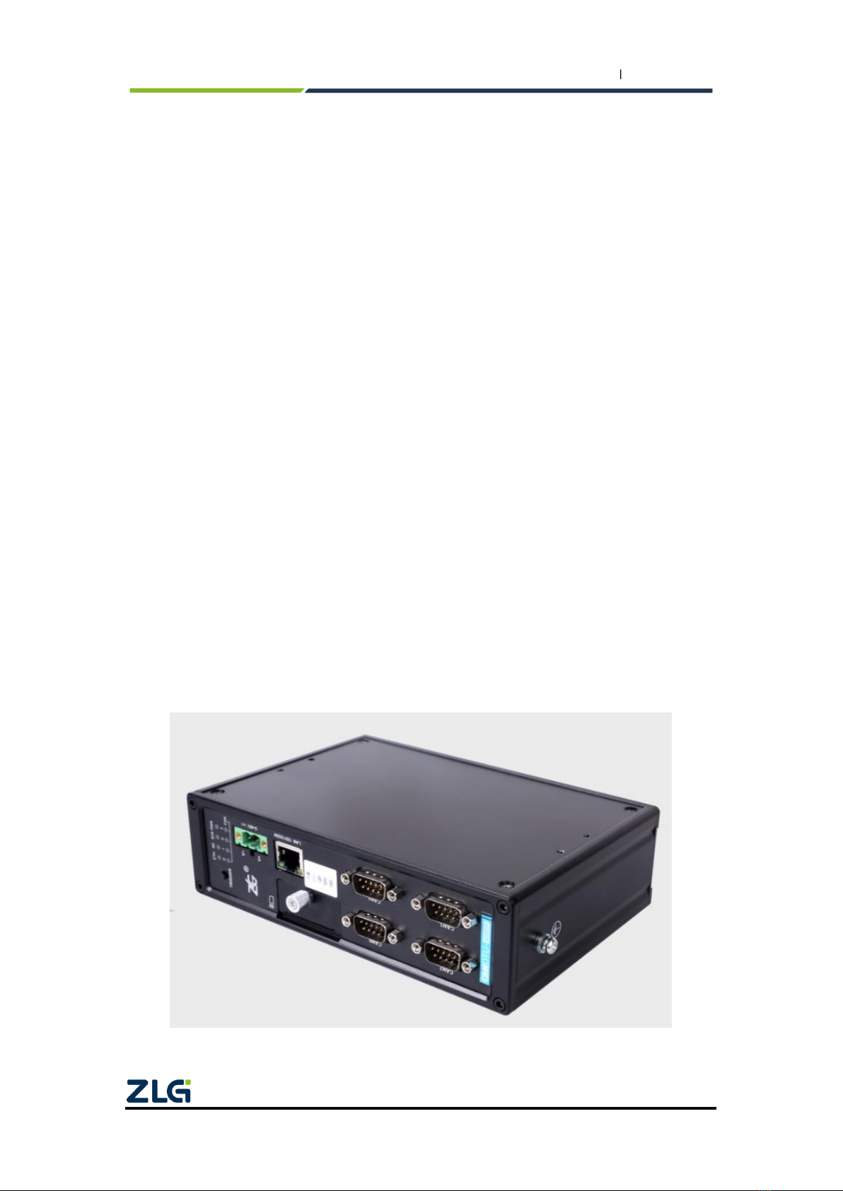
ZLG CANDTU-400ER User manual

Product User Manual
CANDTU-400ER
CAN Bus Message Records and Wireless Data Transmission Equipment
User Manual
UM01010101 V1.01 Date: 2019/11/01
Category
Contents
Keywords
CAN-Bus message logging, Ethernet
Description
Product User Guide
©2021 Guangzhou ZLG Electronics Technology Co.,Ltd.

CANDTU-400ER
CAN Bus Message Recording and Wireless Data Transmission Equipment User Manual
©2021 Guangzhou ZLG Electronics Technology Co.,Ltd.
i
User Manual
Revision History
Version
Date
Reason
V1.00
May 5, 2019
Created
V1.01
November 01,
2019
Corrected the document description

CANDTU-400ER
CAN Bus Message Recording and Wireless Data Transmission Equipment User Manual
©2021 Guangzhou ZLG Electronics Technology Co.,Ltd.
1
User Manual
Contents
1. Product Introduction.....................................................................................1
1.1 Product Overview...................................................................................................1
1.2 Features..................................................................................................................2
1.3 Typical Applications................................................................................................2
2. Product Specifications .................................................................................3
2.1 Electrical Parameters.............................................................................................3
2.2 Operating Temperature ..........................................................................................3
2.3 Protection Level......................................................................................................3
2.4 Shock and Vibration Level......................................................................................4
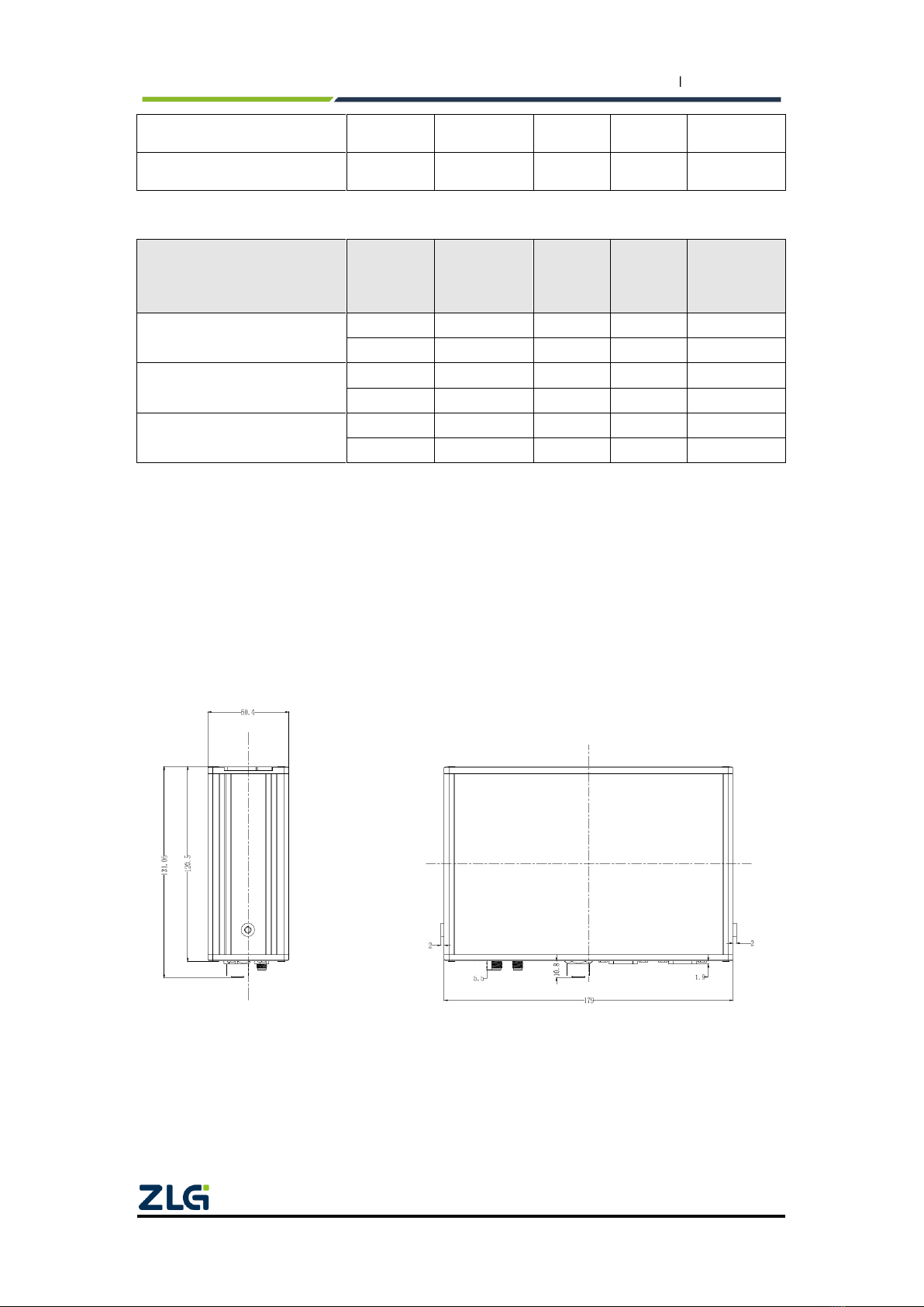
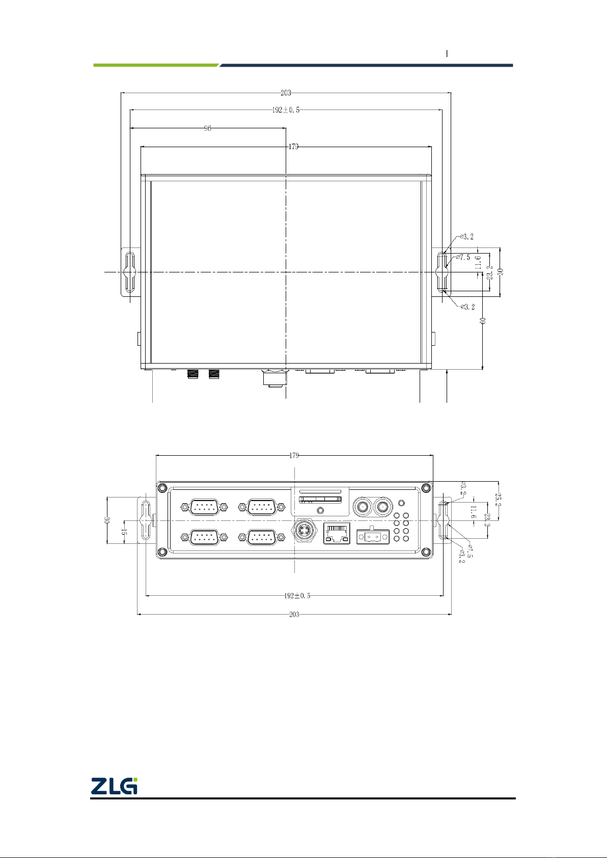
2.5 Mechanical Dimensions .........................................................................................4
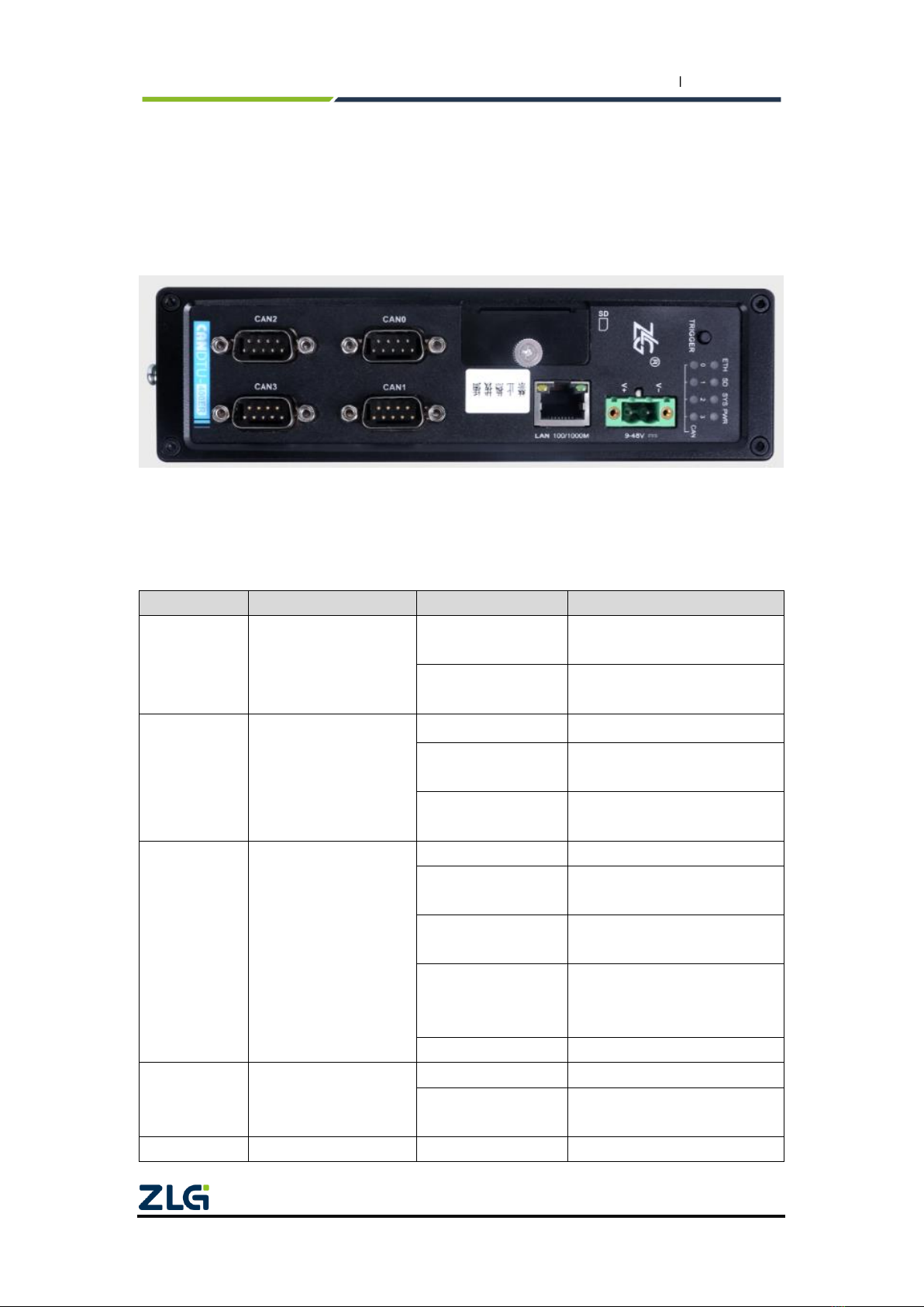
3. Hardware Interfaces.....................................................................................6
3.1 Panel Layout...........................................................................................................6
3.2 Indicators................................................................................................................6
3.3 Button .....................................................................................................................7
3.4 Power Interface ......................................................................................................7
3.5 CAN-bus Interface..................................................................................................8
3.6 Ethernet Interface.................................................................................................10
3.7 SD Card Interface.................................................................................................10
4. Configuration Tool Installation and Introduction .........................................11
4.1 Software Installation.............................................................................................11
4.2 Device Connection ...............................................................................................11
4.2.1 Device Selection ........................................................................................11
4.2.2 Network Configuration................................................................................12
4.3 Function Description.............................................................................................14
4.3.1 CAN Configuration.....................................................................................15
4.3.2 Filtering.......................................................................................................16
4.3.3 Triggering ...................................................................................................17
4.3.4 Flipping the Recorder.................................................................................23
4.3.5 Equipment Data .........................................................................................24
4.3.6 Firmware Upgrade .....................................................................................25
4.3.7 Data Converter...........................................................................................26
4.3.8 Storage Space Allocation...........................................................................29
4.3.9 Network Connection Configuration............................................................29
4.3.10 Network Transmission Filtering................................................................30
4.3.11 Network Frame Format ............................................................................32
4.3.12 Network Server Settings..........................................................................32
4.3.13 Menu Operation .......................................................................................34
4.3.14 Setting and Getting the Device Clock......................................................36
4.3.15 Downloading and Obtaining Device Configurations................................37
4.3.16 Pausing and Resuming Records.............................................................37
4.3.17 Clearing Device Storage..........................................................................38

CANDTU-400ER
CAN Bus Message Recording and Wireless Data Transmission Equipment User Manual
©2021 Guangzhou ZLG Electronics Technology Co.,Ltd.
2
User Manual
4.3.18 Device Information...................................................................................38
5. Product Fault Report Form.........................................................................39
6. Product Return Procedure .........................................................................40
7. Disclaimer..................................................................................................41

CANDTU-400ER
CAN Bus Message Recording and Wireless Data Transmission Equipment User Manual
©2021 Guangzhou ZLG Electronics Technology Co.,Ltd.
1
User Manual
1. Product Introduction
1.1 Product Overview
It mainly includes: product introduction (overview), product pictures (function
instructions may not be provided), and a detailed list of functions.
In the CAN bus troubleshooting, the biggest difficulty is occasional faults. This makes
engineers or even CAN experts unable to accurately identify the fault cause. For example,
the pitch system of the wind turbine had a CAN data transmission interruption in 72 hours;
the dashboard of a new energy vehicle appeared "blank" once during a 10,000 km drive,
but this could not reoccur; the high-speed train experienced an emergency deceleration
due to abnormal CAN communication during a 2,000 km journey. These occasional
CANFD communication exceptions have frightened engineers like time bombs. If one
CAN bus data recorder is installed on an occasion prone to faults, it is equivalent to a
"black box" to record CAN data, which helps analyze the fault cause.
Guangzhou ZLG Electronics Co., Ltd., as a leading manufacturer of the domestic
CAN bus, has developed CANDTU series products for troubleshooting CAN buses, which
can record CAN messages offline. It can easily complete the message recording and
on-site monitoring of applications such as vehicles, ships, elevators, wind turbines, and
construction machinery.
CANDTU-400ER series products are 4-channel CAN bus data recorders with storage,
which can run independently from PC and store CAN message data for a long time, which
helps users analyze and troubleshoot. The recorder can transfer the recorded data to a
PC via an SD memory card on the Ethernet. After format conversion of the raw data, users
can carry out offline analysis and evaluation of the recorded data by using CANoe and
CANScope.
Figure 1.1 Overall product rendering

CANDTU-400ER
CAN Bus Message Recording and Wireless Data Transmission Equipment User Manual
©2021 Guangzhou ZLG Electronics Technology Co.,Ltd.
2
User Manual
1.2 Features
Table 1.1 Product features
CAN channel
Number of channels: four user-configurable CAN channels
Interface type: high-speed CAN
Baud rate: arbitrarily programmable between 5 Kbps and 1 Mbps
Maximum receive data flow: 4,500 frames/s
Surge protection: 1 kV (Class A)
Electromagnetic isolation: 3.5 kV
PC interface
100M/1000M Ethernet;
Message recording
and storage
Storage capacity: SD memory card of a maximum of 64 GB
Storage mode: all storage, timing storage
Full mode: rolling record, full stop
Trigger mode: conditional trigger, external trigger
Find and location: Manual time stamping
Data export:ASC, CSV, or CAN data for CANoe, CANScope
analysis
Real-time clock
Built-in rechargeable lithium battery
Software
resources
Supports the general configuration function library, which helps
users develop application programs with VC, VB, Delphi and C++
Builder
Supports the configuration tool CANDTU
Power supply
voltage
DC 9 ~ 48V
Power
consumption
2.5W
Range of
temperature
Operating temperature: -40℃to +85℃
Storage temperature: -40℃to +85℃
External dimension
179mm×131.5mm×50.4mm
1.3 Typical Applications
High-speed train operation fault detection and troubleshooting
Subway train running fault detection and troubleshooting
Train control system operation fault detection and troubleshooting
Wind turbine CAN communication fault detection
Multi-channel CAN communication records and fault analysis for traditional vehicles
and new energy vehicles
Ship CANFD communication fault detection and troubleshooting
Coal mine CAN communication fault analysis
Elevator operation fault detection and troubleshooting
Construction machinery operation fault detection and troubleshooting
Operation detection and troubleshooting of aerospace vehicles and ancillary
equipment

CANDTU-400ER
CAN Bus Message Recording and Wireless Data Transmission Equipment User Manual
©2021 Guangzhou ZLG Electronics Technology Co.,Ltd.
3
User Manual
2. Product Specifications
2.1 Electrical Parameters
Table 2.1 Electrical parameters
Parameter Name
Conditions
Rating
Unit
Minimum
Typical Value
Maximum
Operating voltage
DC
9
48
V
Power consumption
2.5
W
2.2 Operating Temperature
Table 2.2 Operating temperature
Parameter Name
Conditions
Rating
Unit
Minimum
Typical
Value
Maximum
Operating
temperature
SD card not included
-40
-
85
℃
Storage
temperature
SD card not included
-40
-
85
℃
Note: The operating temperature of the device depends on the SD card. The
specifications are as follows:
SD card specifications: -25°C to +85°C (operating temperature), -40°C to +85°C (storage
temperature).
2.3 Protection Level
Table . 3 Protection level-electrostatic discharge immunity test (IEC61000-4-2)
Interface
Conditions
Test Level
Test
Voltage
(kV)
Test
Result
Remarks
Power supply
Level 4
8
Class A
Contact
discharge
CAN bus
Level 4
8
Class A
Contact
discharge
Ethernet
Level 4
8
Class A
Contact
discharge
Buttons, Indicators
Level 4
15
Class A
Air discharge
Table . 4 Protection level-electrical fast transient pulse group immunity test (IEC61000-4-4)
Interface
Conditions
Test Level
Test
Voltage
(kV)
Test
Result
Remarks
Power supply
Level 3
2
Class A
Capacitive
coupling

CANDTU-400ER
CAN Bus Message Recording and Wireless Data Transmission Equipment User Manual
©2021 Guangzhou ZLG Electronics Technology Co.,Ltd.
4
User Manual
CAN bus
Level 3
1
Class B
Capacitive
coupling
Ethernet
Level 3
2
Class A
Capacitive
coupling
Table . 5 Protection level-surge (impact) test (IEC61000-4-5)
Interface
Conditions
Test level
Test
Voltage
(kV)
Test
Result
Remarks
Power supply
Level 3
1
Class A
Line-line
Level 3
2
Class A
Line-ground
CAN bus
Level 3
1
Class B
Line-line
Level 3
2
Class B
Line-ground
Ethernet
Level 3
1
Class A
Line-line
Level 3
2
Class A
Line-ground
Note: For details, see the attachment Electromagnetic Compatibility Test Report.pdf
2.4 Shock and Vibration Level
Withstands the vibration and shock of grade 1 class B vehicle body installation
specified in GB/T 21563 without damage and failure
For details, see the attached certification report
2.5 Mechanical Dimensions
The following figures shows the mechanical dimensions (unit: mm)
Figure 2.1 Mainframe dimensions

CANDTU-400ER
CAN Bus Message Recording and Wireless Data Transmission Equipment User Manual
©2021 Guangzhou ZLG Electronics Technology Co.,Ltd.
5
User Manual
Figure 2.2 Installation method 1
Figure 2.3 Installation method 2

CANDTU-400ER
CAN Bus Message Recording and Wireless Data Transmission Equipment User Manual
©2021 Guangzhou ZLG Electronics Technology Co.,Ltd.
6
User Manual
3. Hardware Interfaces
This section describes the hardware interfaces of the CANDTU-400ER device.
3.1 Panel Layout
Figure 3.1 shows the device panel layout.
Figure 3.1 Panel layout
3.2 Indicators
Table 3. 1 LED indicators
Identification
Function
STATUS
Description
PWR
Power indicator
The indicator is on
The device is powered on
properly
The indicator is off
The device is powered off, or
the power supply is abnormal
SYS
System running status
indicator
Green flashing light
The device is normal
The red indicator
flashes slowly
SD card abnormal
The red indicator
flashes quickly
Device power-off state
SD
SD card status light
Normally on
The SD card is ready
The green light
flashes quickly
SD card ready status
The green light
flashes slowly
SD card write status
The red indicator
flashes slowly
The SD card writes data, and
there is insufficient channel
space
The indicator is off
The SD card has not started
ENT
Indicates the Ethernet
status
Green flashing light
Ethernet data transmission
The indicator is off
Ethernet has no data
transmission or is not connected
CAN0、1
CAN channel
The indicator is off
The CAN channel is not

CANDTU-400ER
CAN Bus Message Recording and Wireless Data Transmission Equipment User Manual
©2021 Guangzhou ZLG Electronics Technology Co.,Ltd.
7
User Manual
CAN2、3
transceiver status
indicator
activated
Green flashing light
The CAN channel receives data
properly
The red indicator is
on
The CAN channel received an
error frame
3.3 Button
The device provides a trigger button. The shell is identified as "Trigger". Its function is
to mark the CAN message data, so that you can locate the data recorded in the SD card.
In addition, this button can be used for firmware upgrade.
Table 3.1 Button functions
Operation
Function
Conditions
Manipulation
Symptom
Stop
recording
Stop storing
CAN message
data
Normal
recording, or
resumed
recording
Hold down the button for
more than 3 seconds and
less than 10 seconds to stop
recording. Then you can
safely eject the SD card
The buzzer beeps
Recover
records
Recover
storage
CAN message
data
Recording
has stopped,
and the card
exists
Short-press the button to
resume recording
Return to the state before
the stop;
The buzzer beeps twice
Once the configuration is
downloaded, the recording
can be resumed
Recording
has stopped
but the card
does not
exist
Reinsert the card to resume
recording
User tag
Mark
CAN message
data
Normal
record
Press the button for more
than 200 ms and no more
than 2s to mark the data.
The REC indicator
flashes once;
The buzzer beeps briefly.
User
upgrade
Upgrade
device
firmware
Power-on
process
Insert the SD card, press
and hold the button, and
power on the device;
Release the button after
three short buzzer beeps
The buzzer makes three
short beeps
Restore
network
parameters
Restore
default
network
parameters
Device
running
process
Hold down the button for
more than 10s, and release
the button
The buzzer beeps long
while the button is
pressed
When the button is
released, the buzzer
beeps four times in a row
3.4 Power Interface
The rated voltage of the power input of the equipment is DC 9-48 V, and the casing is
marked as "DC 9-48V". The physical form of the interface is a 5.08 terminal. 错误!未找到
引用源。, 错误!未找到引用源。 and 错误!未找到引用源。 list the interface diagram, signal
definition, and interface specifications.
Table 3.2 Power interface

CANDTU-400ER
CAN Bus Message Recording and Wireless Data Transmission Equipment User Manual
©2021 Guangzhou ZLG Electronics Technology Co.,Ltd.
8
User Manual
Type
Schematic Diagram
5.08 terminal
Table 3.4 Terminal signal definitions
Function
Interface
Signal
Definition
Signal Description
Interface Type
5.08 interface
Power
supply
V+
positive electrode of power
√
V-
negative electrode of power
√
Table 3.3 Power interface specifications
Parameter Name
Conditions
Rating
Unit
Minimum
Typical Value
Maximum
Working voltage
DC
9
48
V
Power
consumption
2.5
W
3.5 CAN-bus Interface
The device provides four isolated CAN-Bus interfaces. The shell identification is
"CAN0", "CAN1", "CAN2", and "CAN3". The physical form of the interface is a DB9
terminal. 错误!未找到引用源。, 错误!未找到引用源。 and 错误!未找到引用源。 list the
interface diagram, signal definition, and interface specifications.
Table 3.4 Pin definitions
Type
Schematic Diagram
DB9 terminal

CANDTU-400ER
CAN Bus Message Recording and Wireless Data Transmission Equipment User Manual
©2021 Guangzhou ZLG Electronics Technology Co.,Ltd.
9
User Manual
Pin definitions
Table 3.5 Signal definitions
Function
Interface
Signal
Definition
Signal Description
Pin Number
CAN0~CAN3
CAN0_L
CAN0 data transceiver differential inverted
signal
2
CAN0_GND
CAN0 isolated ground
3、6
CAN0_H
CAN0 data transceiver differential positive
phase signal
7
CAN_FG
Shielding ground
5
NC
Not connected
1、4、8、9
Table . 8 CAN-Bus interface specifications
Parameter
Minimum
Typical
Value
Maximum
Unit
Communication baud rate
5k
1M
bps
Number of nodes
110
pcs
Dominant level (logic 0)
CANH
2.75
3.5
4.5
V
CANL
0.5
1.5
2
Recessive level (logic 1)
CANH
2
2.5
3
CANL
2
2.5
3
Differential level
Dominant (logic 0)
1.2
2
3.1
Recessive (logic 1)
-0.5
0
0.05
Maximum withstand
voltage of the bus pin
-18
18
Instantaneous voltage of
the bus
-100
+100
Isolation voltage (DC)
3500
V
Figure 3.2 Typical high-speed CAN network connection
The CAN bus adopts balanced transmission. ISO11898-2 stipulates: In the

CANDTU-400ER
CAN Bus Message Recording and Wireless Data Transmission Equipment User Manual
©2021 Guangzhou ZLG Electronics Technology Co.,Ltd.
10
User Manual
high-speed CAN, a 120 ohm terminal resistor needs to be connected to the network
terminal node to eliminate signal reflection on the bus and avoid signal distortion. Figure
3.2 shows the high-speed CAN network topology.
The device has a built-in 120 ohm terminal resistance, which can be configured to
turn on or off by using the configuration tool CANDTU. For operation details, see 4.3.1.
Note: The bus communication distance and communication rate are related to the
field application and can be designed according to the actual application and related
standards. The CAN-Bus cable can use ordinary twisted pair, shielded twisted pair or
standard bus communication cable. In long-distance communication, the terminal
resistance value needs to be selected according to the communication distance, cable
impedance and number of nodes.
3.6 Ethernet Interface
The device provides one Ethernet interface. The physical form of the interface is RJ45, which realizes the
communication between the device and the PC. The interface 100/1000M specification, interface
schematic diagram and signal definition are shown in Table 3.9.
Table 3.9 Ethernet interface
Type
Schematic Diagram
RJ45 terminal
3.7 SD Card Interface
The device provides one SD card interface, which supports a maximum of 64 GB SD
memory card for storing CAN bus message data. The interface adopts a self-locking card
slot, and the SD card can be locked after the card is inserted according to the direction of
the casing logo to prevent accidental falling off during use. When pulling out the card, just
push it inwards to eject the SD card.
The SD card uses the EXT4 file system. Connecting the SD card through a card
reader cannot directly view the SD card data in the Windows system. You need to install a
tool plug-in that supports the EXT file system (for example, Ext2Fsd).
The device data can be obtained directly in the window by using the method in
section 4.3.5.
Note: Do not forcibly pull out the card during the device operation; otherwise, it
may cause data loss or damage to the memory card and device exceptions! If
necessary, after powering off the device, open the SD card slot cover, push in
gently and eject the SD card.

CANDTU-400ER
CAN Bus Message Recording and Wireless Data Transmission Equipment User Manual
©2021 Guangzhou ZLG Electronics Technology Co.,Ltd.
11
User Manual
4. Configuration Tool Installation and Introduction
4.1 Software Installation
Double-click the software installation package to install the software, and select the
installation path.
4.2 Device Connection
4.2.1 Device Selection
Figure 4.1 Selecting a device

CANDTU-400ER
CAN Bus Message Recording and Wireless Data Transmission Equipment User Manual
©2021 Guangzhou ZLG Electronics Technology Co.,Ltd.
12
User Manual
Figure 4.2 Searching a device
1) As shown in Figure 4.1, select a device model. The device search interface is
displayed, as shown in Figure 4.2;
2) Click the "Search Device" button on the device search interface. The device list
displays the search results;
3) Select a device and click the "OK" button to connect the device.
4.2.2 Network Configuration

CANDTU-400ER
CAN Bus Message Recording and Wireless Data Transmission Equipment User Manual
©2021 Guangzhou ZLG Electronics Technology Co.,Ltd.
13
User Manual
Figure 4.3 Device network configuration 1
Figure 4.4 Device network configuration 2
After searching for the device, select the device, as shown in Figure 4.3. Click the "Modify"

CANDTU-400ER
CAN Bus Message Recording and Wireless Data Transmission Equipment User Manual
©2021 Guangzhou ZLG Electronics Technology Co.,Ltd.
14
User Manual
button to display the "Device Information" interface, as shown in Figure 4.4.
IP address configuration: automatic acquisition (DHCP) and manual setting.
*The CANDTU-400ER model does not have WiFi and LTE functions.
4.3 Function Description
Figure 4.5 Main interface of the tool
After the program is installed, there will be shortcuts to the configuration tool on the
desktop and start menu. After double-clicking the desktop icon to start the program, the
CAN configuration page is displayed by default, as shown in Figure 4.5. The configuration
tool interface is divided into four parts:
1) Menu bar:
Provide all operation commands of the configuration tool, including common
operation commands in the shortcut toolbar, restore factory settings, etc.;
2) Shortcut Toolbar
Provide common operation buttons of the configuration tool to complete the quick
operation of commands;
3) Side navigation bar
Provide multiple categories of information tabs to quickly switch tabs;
4) Information settings bar
Operate the specific configuration information based on the options in the left

CANDTU-400ER
CAN Bus Message Recording and Wireless Data Transmission Equipment User Manual
©2021 Guangzhou ZLG Electronics Technology Co.,Ltd.
15
User Manual
navigation bar.
The following describes the function and meaning of each configuration parameter of the
configuration tool.
4.3.1 CAN Configuration
Figure 4.6 AN configuration tab
The CAN Configuration tab contains the following parameters:
1) Channel selection
Selected: Enable the corresponding CAN channel.
Deselected: Disable the corresponding CAN channel.
2) Communication mode
Normal mode:
Listen only mode:
3) Communication baud rate
Provides commonly used CAN communication baud rates.
4) Use a built-in 120-ohm resistor (connected by default)
Selected: Connect the built-in 120-ohm resistor termination resistor
corresponding to the CAN channel.
Deselected: Disconnect the built-in 120-ohm resistor termination resistor of the

CANDTU-400ER
CAN Bus Message Recording and Wireless Data Transmission Equipment User Manual
©2021 Guangzhou ZLG Electronics Technology Co.,Ltd.
16
User Manual
corresponding CAN channel.
5) Custom baud rate
If the provided common CAN communication baud rate cannot meet the
requirements, select the custom baud rate check box and enter the baud rate.
6) Record error frames
Selected: Record CAN error frames.
Deselected: CAN error frames will not be recorded.
4.3.2 Filtering
Figure 4.7 Filter Settings Tab
The configuration tool supports a maximum of 64 filtering rules per channel. Filter
configurations based on the ID. Support channel independent enable filter and filter mode.
When the blacklist is selected, the device does not receive the ID packets added in
the list. When the whitelist is selected, the device only receives ID packets added in the
list.
The Filter tab contains the following parameters:
Filter modes: blacklist, whitelist
Start and end frame IDs
Mode selection: standard frame single ID, standard frame group ID, extended
Table of contents
Other ZLG Recording Equipment manuals