ZLG USBCANFD Series Operational manual

Category
Contents
Keywords
USB to CANFD card, USBCANFD-100U/200U
Abstract
USBCANFD-100U/200U Product Performance Description and User Guide
Product User Manual
USBCANFD-200U/100U
USBCANFD Series CANFD Interface Cards
User Manual
UM01010101 V1.02 Date: 2019/10/21
©2021 Guangzhou ZLG Electronics.,Ltd.

USBCANFD-200U/100U
USBCANFD Series CANFD Interface User Manual
©2021 Guangzhou ZLG Electronics Co., Ltd.
i
User Manual
Revision History
Version
Date
Description
V0.90
January 16, 2018
Created
V1.00
April 10, 2018
Released
V1.01
March 8, 2019
Updated the document header and footer and "Sales and Service Network" content, and
added the "Disclaimer" content
V1.02
October 21, 2019
Changed the product pictures

USBCANFD-200U/100U
USBCANFD Series CANFD Interface User Manual
©2021 Guangzhou ZLG Electronics Co., Ltd.
1
User Manual
Contents
1. Product Introduction.....................................................................................................................1
1.1 Product Overview.........................................................................................................................................1
1.2 Product Appearance.....................................................................................................................................1
1.3 Functions......................................................................................................................................................1
1.4 Product Specifications..................................................................................................................................2
1.4.1 Electrical Specifications .....................................................................................................................2
1.4.2 Operating Temperature......................................................................................................................2
1.5 Mechanical Installation Dimensions.............................................................................................................2
1.6 Typical Applications......................................................................................................................................3
2. Hardware Interfaces.....................................................................................................................4
2.1 Power Cable Connection .............................................................................................................................4
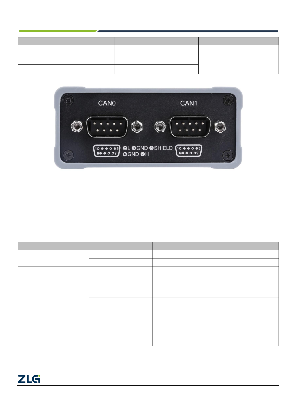
2.2 CAN Communication Interface ....................................................................................................................4
2.3 Signal Indicators...........................................................................................................................................5
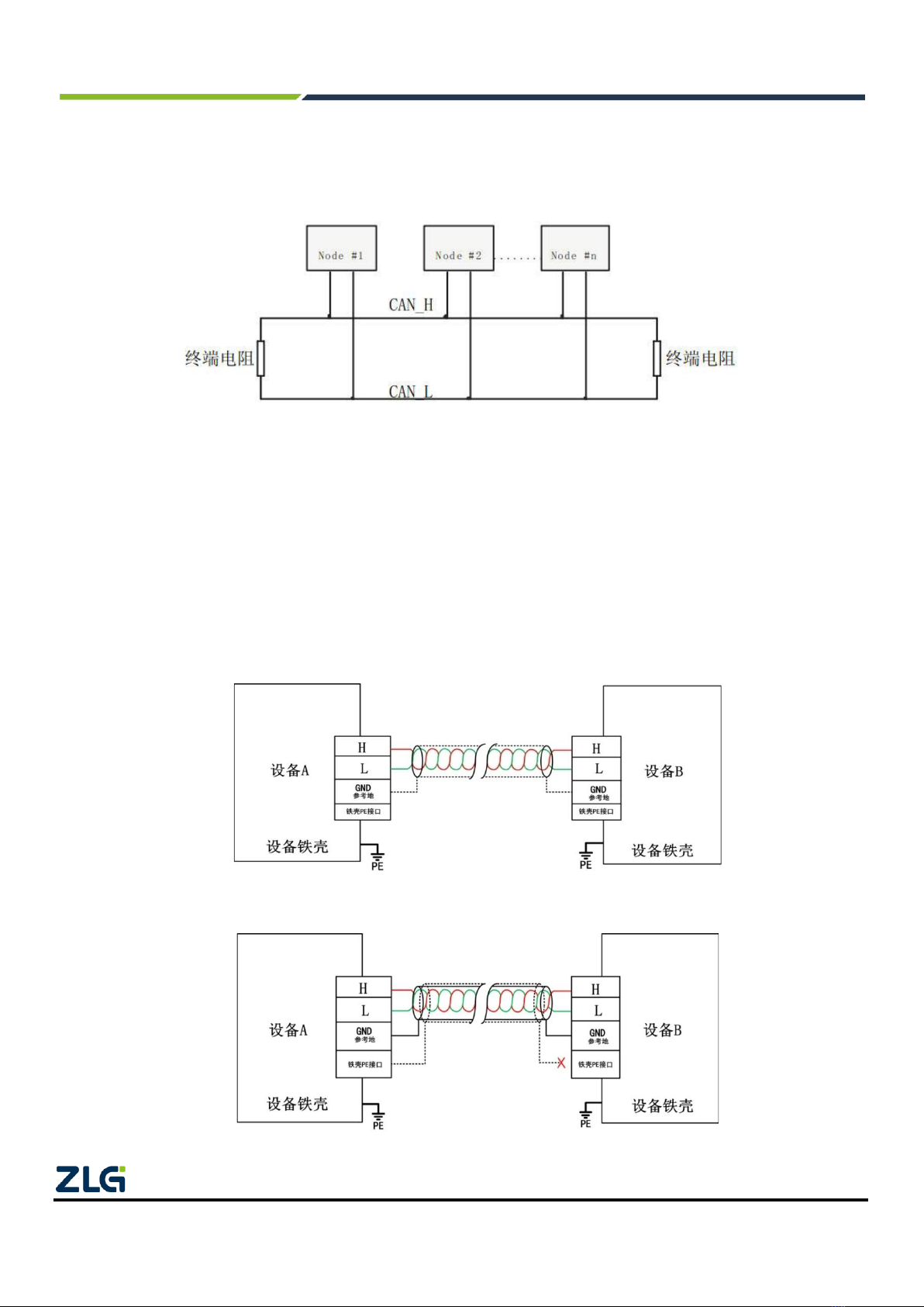
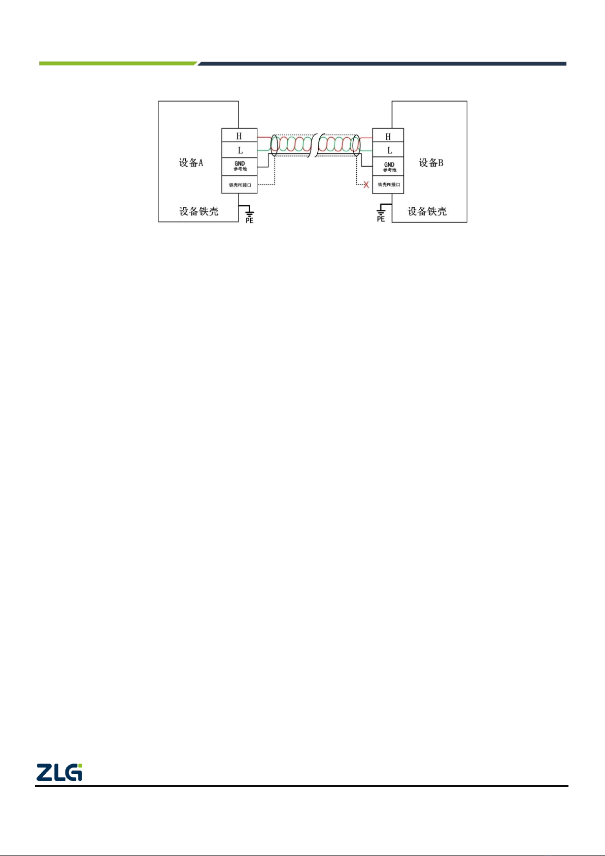
2.4 System Connections ....................................................................................................................................5
3. Driver Installation .........................................................................................................................8
3.1 Installing the Driver under Windows ............................................................................................................8
4. Inspection and Maintenance ......................................................................................................12
5. Packing List................................................................................................................................13
6. Quick Guide ...............................................................................................................................14
6.1 Introduction to ZCANPRO Software ..........................................................................................................14
6.2 Using USBCANFD on ZCANPRO .............................................................................................................14
7. Disclaimer ..................................................................................................................................15

USBCANFD-200U/100U
USBCANFD Series CANFD Interface User Manual
©2021 Guangzhou ZLG Electronics Co., Ltd.
1
User Manual
1. Product Introduction
1.1 Product Overview
USBCANFD-200U (100U) is a high-performance CANFD interface card developed by Guangzhou ZLG
Electronics. It meets the USB2.0 bus specification and integrates two CANFD interfaces (100U integrated one
CANFD interface). The CAN channel integrates an independent electrical isolation protection circuit. The interface
card connects the PC to the CAN(FD) network over the USB port to form a CAN(FD)-bus control node.
The USBCANFD-200U(100U) high-performance CANFD interface card is a powerful tool for CAN(FD)-bus
product development and CAN(FD)-bus data analysis; the USBCANFD-200U(100U) interface card has its own
electrical isolation module, which prevents the interface card from being damaged due to ground circulation and
enhances the system reliability in harsh environments. The USBCANFD-200U(100U) high-performance CAN
interface card supports operating systems such as Windows 7/Windows 10.
Note: USBCANFD-200U (100U) is collectively referred to as USBCANFD interface card below.
1.2 Product Appearance
Figure 1.1 Product appearance
1.3 Functions
⚫The USB interface meets the USB2.0 high-speed specification;
⚫Support CAN2.0A and B protocol and comply with ISO11898-1 specification;
⚫Integrate two CANFD interfaces (USBCANFD-100U integrates one channel);
⚫Compatible with high-speed CAN and CANFD;

USBCANFD-200U/100U
USBCANFD Series CANFD Interface User Manual
©2021 Guangzhou ZLG Electronics Co., Ltd.
2
User Manual
⚫CANFD supports ISO standards and non-ISO standards;
⚫The CAN communication baud rate can be arbitrarily programmable between 4 Kbps and 1 Mbps;
⚫The CANFD baud rate can be arbitrarily programmable between 1 Mbps and 5 Mbps;
⚫Maximum data flow for single channel transmission: 3,000 frames per second (remote frame, single frame
transmission);
⚫The highest data flow rate received by a single channel: 10,000 frames per second (remote frame);
⚫Each channel supports a maximum of 64 ID filters;
⚫Each channel supports a maximum of 100 scheduled messages;
⚫Built-in 120 ohm terminal resistance, which can be connected and disconnected by software control;
⚫Support USB bus power supply and external power supply;
⚫Support ZCANPRO test software (support Windows 7 and Windows 10);
⚫Provide the host computer secondary development interface function.
1.4 Product Specifications
1.4.1 Electrical Specifications
The USBCANFD interface card needs a certain electrical environment to work safely and stably. Table 1.1
lists the electrical parameters of the interface card. Exceeding the parameters listed in the table may cause the
product to work unstable and fail, or even burn the module.
Table 1.1 Electrical specifications of USBCANFD interface card
Parameter
Test Conditions
Minimum
Typical Value
Maximum
Unit
Operating
voltage
External input DC power
supply
Two CAN
transceivers
9
24
48
V
USB powered
Two CAN
transceivers
4.75
5
5.25
V
Operating
current
External input DC power
supply
VIN=24V
--
85
--
mA
USB powered
VBUS=5V
--
110
--
mA
CAN
interface
Bus pin withstand voltage
CANH, CAHL
-42
--
42
V
Terminal resistance
Enable terminal
resistance
--
120
--
Ω
Isolation withstand
voltage
Leakage current less
than 1 mA
2500
--
--
VDC
1.4.2 Operating Temperature
The USBCANFD interface card meets the requirements of industrial grade products, and its applicable
working temperature range is –40°C to +85°C. Using the interface card in too low or too high ambient temperature
will shorten its service life.
1.5 Mechanical Installation Dimensions
The external dimensions of the USBCANFD interface card are 115 mm x 80 mm x 35 mm, as shown in Figure

USBCANFD-200U/100U
USBCANFD Series CANFD Interface User Manual
©2021 Guangzhou ZLG Electronics Co., Ltd.
3
User Manual
1.2.
Figure 1.1 USBCANFD-200U dimensions
Note: The unit is mm
1.6 Typical Applications
⚫CAN(FD)-Bus network diagnosis and test
⚫Automotive electronics applications
⚫Electric power communication network
⚫Industrial control equipment
⚫High-speed, large data volume communication

USBCANFD-200U/100U
USBCANFD Series CANFD Interface User Manual
©2021 Guangzhou ZLG Electronics Co., Ltd.
4
User Manual
2. Hardware Interfaces
2.1 Power Cable Connection
The USBCANFD interface card is designed with two power supply methods. One is to supply power through
the USB port, and the other is to supply power through DC power supply. You can select one of the power supply
methods. You can also connect DC power supply and USB cable at the same time. The external power supply
mode is suitable for situations where the PC uses a USB bus hub, or is connected to multiple USB terminal devices,
which prevents USB port from providing sufficient current to the USBCANFD interface card.
The USB cable is type B (square opening), with locking screws at both ends of the cable. One USB cable is
provided before delivery. The DC socket is suitable for a round plug with an outer diameter of 5.5 mm, and there
is no positive or negative requirement for the plug inside and outside. The DC power supply and its cables need
to be provided by the customer, and the DC power supply meets +9 V to +48 V. Figure 2.1 shows the DC power
interface and USB interface.
Figure 2.1 Left interface of USBCANFD-200U
2.2 CAN Communication Interface
A DB9 connector is used for the CAN communication interface of the USBCANFD interface card, and the
signal definition of the interface pins meets the requirements of the CiA standard. Table 2.1 lists the pin signal
definition of DB9, and Figure 2.2 shows the interface,
Table 2.1 DB9 pin signal definition
Pin
Signal
Description
Figure
1
--
Reserved
2
CAN_L
CAN bus dominance is low
3
CAN_GND
CAN reference ground
4
--
Reserved
5
CAN_SHLD
CAN shield ground
6
CAN_GND
CAN reference ground
Continued

USBCANFD-200U/100U
USBCANFD Series CANFD Interface User Manual
©2021 Guangzhou ZLG Electronics Co., Ltd.
5
User Manual
Pin
Signal
Description
Figure
7
CAN_H
CAN bus is highly dominant
8
--
Reserved
9
--
Reserved
Figure 2.2 CAN interface
2.3 Signal Indicators
The USBCANFD-200U interface card has one power indicator PWR and one two-color SYS indicator. Each
two-color indicator corresponds to one CAN channel, indicating the operating status of the CAN channel. Figure
2.1 shows the location of the equipment indicator, and Table 2.2 lists the specific indicator function definition.
Table 2.2 Description of USBCANFD-200U (100U) interface card indicators
Indicator
STATUS
Indication status
PWR
Green
Power on equipment
Off
The device is not powered on
SYS
Red
The driver is not installed properly, or the USB cable is not
connected
Green
The USB driver has been installed, and the USB cable has
been connected
Green flashing
The USB is communicating with the device
Flash in red
USB and device communication error
CAN0, CAN1
Off
The CAN channel is not open
Green
The CAN channel is open
Green flashing
The CAN channel is transmitting messages
Flash in red
CAN channel bus error
2.4 System Connections
When the USBCANFD interface card is connected to the CAN-bus bus, it is only necessary to connect

USBCANFD-200U/100U
USBCANFD Series CANFD Interface User Manual
©2021 Guangzhou ZLG Electronics Co., Ltd.
6
User Manual
CAN_L to CAN_L and CAN_H to CAN_H signals. A linear topology is adopted for the CAN-bus network , and
the two terminals of the bus need to be installed with 120 ohm terminal resistors; if the number of nodes is
greater than 2, the intermediate nodes do not need to install 120 ohm terminal resistors. For branch connections,
the length should not exceed 3 meters. Figure 2.3 shows the connection of CAN-bus bus.
Figure 2.3 Linear topology of the CAN-bus network
In the CAN-bus network, shielded wires are often used for interconnection, so as to enhance the anti-
interference ability. However, there are many types of shielded wires and field wiring is complicated. Therefore,
the wiring diagrams of different types of cables in application are shown below, including the connection diagrams
of double-core single-layer shielded wire, double-core double-layer shielded wire, and three-core single-layer
shielded wire (The "equipment iron shell" in the pictures refers to the outer shell of the device, which is grounded
by default). Regardless of the type of cable, reasonable changes must be made according to the complexity of the
field wiring. Ensure the reliable grounding of the single point of the shielded wire or ground wire at any time, and
carry out on-site wiring in strict accordance with the wiring specifications to minimize communication errors and
abnormalities, and improve the communication quality and service life of the bus.
Figure 2.4 Double-core single-layer shielded cable connection

USBCANFD-200U/100U
USBCANFD Series CANFD Interface User Manual
©2021 Guangzhou ZLG Electronics Co., Ltd.
7
User Manual
Figure 2.5 Double-core double-layer shielded cable connection
Figure 2.6 Three-core single-layer shielded cable connection

USBCANFD-200U/100U
USBCANFD Series CANFD Interface User Manual
©2021 Guangzhou ZLG Electronics Co., Ltd.
8
User Manual
3. Driver Installation
This document uses a PC running Windows 7 as an example to describe how to install the USBCANFD-200U
(100U) driver.
3.1 Installing the Driver under Windows
Connect the USBCANFD-200U (100U) interface card to the computer with a USB cable, and ensure that the
device is powered properly.
Right-click [Computer] and choose [Properties] (as shown in Figure 3.1) to start the Device Manager. Before
the driver is installed, the Device Manager is displayed, as shown in Figure 3.2. If the device manager does not
display the message, check that the USB cable is connected correctly, the USB port of the computer is disabled,
and the PWR indicator is on.
Figure 3.1 Staring the computer device manager

USBCANFD-200U/100U
USBCANFD Series CANFD Interface User Manual
©2021 Guangzhou ZLG Electronics Co., Ltd.
9
User Manual
Figure 3.2 Starting the computer device manager
Right-click [USBCANFD] and choose [Update Driver Software]. The update driver software interface appears,
as shown in Figure 3.3.
Figure 3.3 Browsing the computer to find the driver software

USBCANFD-200U/100U
USBCANFD Series CANFD Interface User Manual
©2021 Guangzhou ZLG Electronics Co., Ltd.
10
User Manual
As shown in Figure 3.4, click [Browse], select the official USBCANFD driver folder, click [Next], and wait until
the driver is installed.
Figure 3.4 Finding the driver and install it
After the installation is complete, the message "The driver file has been successfully updated" appears.
Click the [Close] button to complete the installation, as shown in Figure 3.5.
Figure 3.5 Finding the driver and install it

USBCANFD-200U/100U
USBCANFD Series CANFD Interface User Manual
©2021 Guangzhou ZLG Electronics Co., Ltd.
11
User Manual
After the driver is installed, is displayed in the device manager, indicating that the driver is
installed correctly. The device SYS indicator turns from red to green. At this time, the CANFD card has been
connected to the PC, and the host computer software can send and receive CAN (FD) messages. It is
recommended to use the ZCANPRO software provided by ZLG Electronics as the host computer software. Users
can also develop their own host computer software by using the provided secondary development function library.

USBCANFD-200U/100U
USBCANFD Series CANFD Interface User Manual
©2021 Guangzhou ZLG Electronics Co., Ltd.
12
User Manual
4. Inspection and Maintenance
The main electrical components of the USBCANFD interface card are semiconductor components. Although
it has a long life, it may also age quickly under inappropriate conditions. Periodic inspections should be carried
out to ensure that the required conditions are maintained. It is recommended to check at least once every 6
months a year. Under unfavorable environmental conditions, inspections should be carried out more frequently.
If you encounter a problem during the maintenance, see Table 4.1 to identify the fault cause. If the fault
persists, contact Guangzhou ZLG Electronics Co., Ltd.
Table 4.1 Inspection and maintenance
No.
Item
Inspection
Standard
Action
1
Power supply
Check for voltage fluctuations at
the power supply side
The external power
supply is within the
allowable voltage
fluctuation range: +9
V to +48 V DC or
USB port power +5 V
DC
Use a voltmeter to check the
power supply at the power
input. Take necessary
measures to keep the
voltage fluctuation within the
range
2
Surrounding
environment
Check the ambient temperature
(including the internal temperature
of the enclosed environment)
-40°C ~ +85°C
Use a thermometer to check
the temperature and ensure
that the ambient
temperature is kept within
the allowable range
Check the ambient humidity
(including the internal humidity of
the enclosed environment)
The relative humidity
must be between
10% and 90% when
there is no air
conditioner
Use a hygrometer to check
the humidity and ensure that
the ambient humidity is kept
within the allowable range
Check for dust, powder, salt, metal
chips
No accumulation
Clean and protect the
equipment
Check that water, oil or chemical
spray should not touch the
equipment
No spray touches the
device
To clean and protect the
equipment
Check for corrosive or flammable
gases in the equipment area
No corrosive or
flammable gas
Check by smelling or using
a sensor
Check vibration and shock levels
Vibration and shock
are within the
specified range
If necessary, install gaskets
or other shock absorbers
Check the noise source near the
equipment
No significant noise
signal source
Isolate the device from the
noise source or protect the
device
3
Installation and
Wiring
Check that each unit is securely
connected and has been safely
locked with the next unit
No looseness
Press the connectors
together completely and
lock them with the slider

USBCANFD-200U/100U
USBCANFD Series CANFD Interface User Manual
©2021 Guangzhou ZLG Electronics Co., Ltd.
13
User Manual
5. Packing List
Table 5.1 USBCANFD-200U Packing List V1.00
No.
Name
Quantity
Unit
Remarks
1
USB to CANFD interface card
1
Piece
2
USB cables
1
Piece
With lock
6
After-sales Service Guide
1
Pcs
7
Certificate of Conformity
1
Piece
8
9

USBCANFD-200U/100U
USBCANFD Series CANFD Interface User Manual
©2021 Guangzhou ZLG Electronics Co., Ltd.
14
User Manual
6. Quick Guide
6.1 Introduction to ZCANPRO Software
ZCANPRO is the supporting software for CAN/CANFD series products produced by Guangzhou ZLG
Electronics Co., Ltd., which can perform operations such as raw data transmission and reception, data playback,
and high-level protocol analysis. The software is easy to operate and powerful, and it is a good helper for CAN
bus testing, monitoring, diagnosis, and development.
ZCANPRO software can be downloaded from the ZLG Electronics official website http://www.zlg.cn.
6.2 Using USBCANFD on ZCANPRO
After the device driver and ZCANPRO are installed, you can use USBCANFD on the ZCANPRO software.
For details about how to use USBCANFD on ZCANPRO, click in the upper right corner of
the software main interface and select [Quick User Guide] in the drop-down box (as shown in
Figure 6.1). For detailed instructions for the ZCANPRO software, see [User Manual].
Figure 6.1 Opening the Quick User Guide

USBCANFD-200U/100U
USBCANFD Series CANFD Interface User Manual
©2021 Guangzhou ZLG Electronics Co., Ltd.
15
User Manual
7. Disclaimer
Based on the principle of providing better service for users, Guangzhou ZLG Electronics Co., Ltd. ("ZLG
Electronics") will try to present detailed and accurate product information to users in this manual. However, due to
the effectiveness of this manual within a particular period of time, ZLG Electronics does not guarantee the
applicability of this document at any time. ZLG Electronics shall reserve the right to update this manual without
prior notice. To get the latest version, please visit the official website of ZLG Electronics regularly or contact ZLG
Electronics. Thank you!
Right to modify the document
Guangzhou ZLG Electronics Co., Ltd. shall reserve the right to modify related documents of USBCANFD
interface card series products at any time without prior declaration.
ESD protection
The USBCANFD interface card series products have electrostatic protection
capabilities to ensure the stable operation of the products. When using USBCANFD
interface card series products, first discharge the static electricity on the body. For example,
wear a reliable grounding static ring, or touch a water pipe connected to the earth.

USBCANFD-200U/100U
USBCANFD Series CANFD Interface User Manual
©2021 Guangzhou ZLG Electronics Co., Ltd.
16
User Manual
Dreams come true with professionalism and dedication.
Guangzhou ZLG
Electronics Co., Ltd.
For more details, please visit
www.zlg.cn
Welcome to call the national service hotline
400-888-4005
Other manuals for USBCANFD Series
1
This manual suits for next models
2
Table of contents
Other ZLG Recording Equipment manuals