ZLG MiniPCIeCANFD User manual

Category
Contents
Keywords
Mini PCI Express, CAN(FD) interface card
Abstract
MiniPCIeCANFD is a dual-channel CAN (FD) interface card that meets
MiniPCIe specifications. Backward compatibility with CAN 2.0 A/B
standard enables industrial notebook computers/portable industrial
computers/single board computers (SBC) to be connected to
CAN/CAN(FD) networks through MiniPCI-E interfaces. This constitutes a
data acquisition and data processing system in CAN/CAN(FD) network
applications such as laboratories, industrial control, and smart
communities.
MiniPCIeCANFD User Manual
Industrial MiniPCI-E Interface CAN (FD) Card
UM01010101 1.2 Date:2022/5/20
User
Manual
©2022 Guangzhou ZLG Electronics Co., Ltd.

MiniPCIeCANFD
PCIe interface CAN (FD) card
©2022 Guangzhou ZHIYUAN Electronics Co., Ltd.
User Manual
Revision History
Version
Date
Description
V1.0
March 18, 2021
Created

MiniPCIeCANFD
PCIe interface CAN (FD) card
©2022 Guangzhou ZHIYUAN Electronics Co., Ltd.
1
User Manual
Contents
1. Product Introduction.....................................................................................................................2
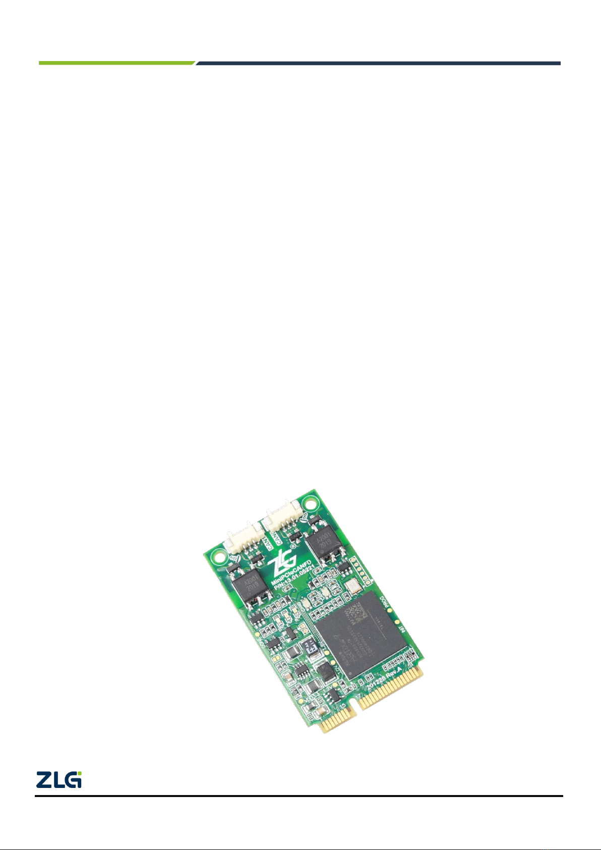
1.1 Product Overview.........................................................................................................................................2
1.2 Functions......................................................................................................................................................3
1.3 Product Specifications..................................................................................................................................3
1.3.1 Electrical Specifications.....................................................................................................................3
1.3.2 Specifications.....................................................................................................................................4
1.3.3 Operating Temperature......................................................................................................................4
1.4 Typical Applications......................................................................................................................................4
2. Hardware Interfaces.....................................................................................................................5
2.1 CAN Communication Interface ....................................................................................................................5
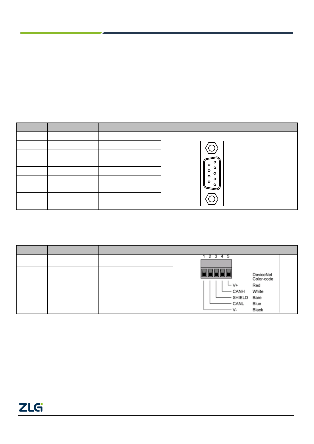
2.2 DB-9 Connector Definition ...........................................................................................................................5
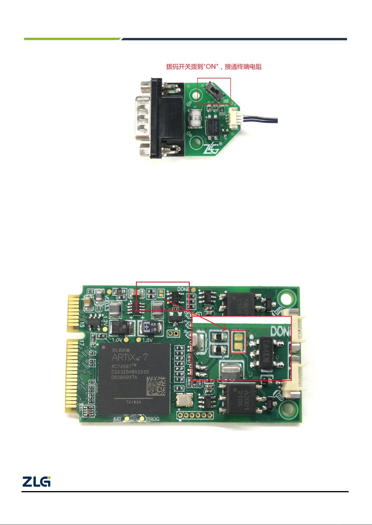
2.3 Terminal Resistance.....................................................................................................................................5
2.4 CAN Second Function Pin Switch................................................................................................................6
2.5 MiniPCIe Goldfinger Definition.....................................................................................................................7
2.6 Signal Indicators...........................................................................................................................................7
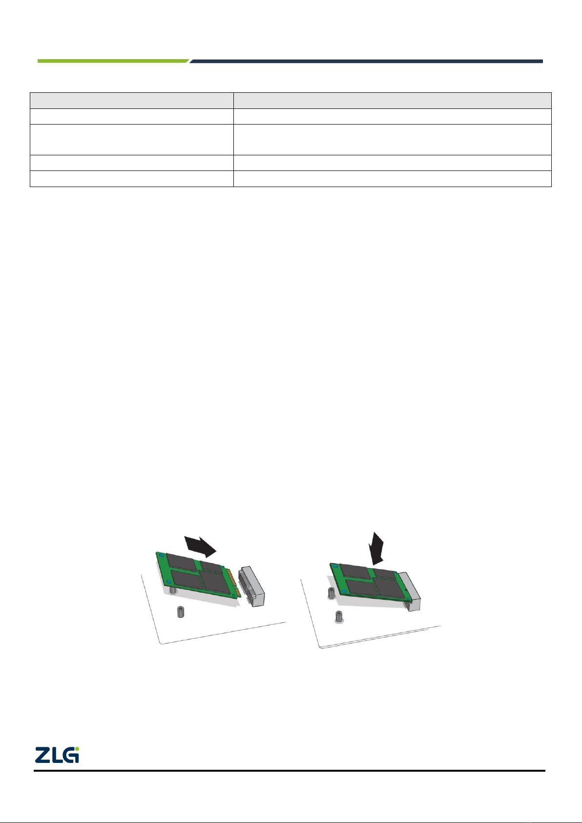
2.7 Board Installation .........................................................................................................................................8
2.7.1 Precautions........................................................................................................................................8
2.7.2 Product Dimensions...........................................................................................................................9
2.8 System Connections....................................................................................................................................9
3. Driver Installation....................................................................................................................... 11
3.1 Installing the Driver under Windows..........................................................................................................11
4. Packing List................................................................................................................................13
5. Quick User Guide.......................................................................................................................14
5.1 Introduction to ZCANPRO Software..........................................................................................................14
5.2 Using MiniPCIeCANFD on ZCANPRO......................................................................................................14
6. Disclaimer..................................................................................................................................15

MiniPCIeCANFD
PCIe interface CAN (FD) card
©2022 Guangzhou ZHIYUAN Electronics Co., Ltd.
2
User Manual
1. Product Introduction
1.1 Product Overview
CAN FD (CAN Flexible Data-rate) is the latest version of the CAN bus, with a maximum of 64 bytes of data,
and a flexible data field with a baud rate of up to 5 Mbps.
The MiniPCIeCANFD CAN(FD) interface card is a MiniPCIe to dual-channel CAN(FD) communication
interface card compatible with PCI Express r1.0a developed by Guangzhou ZLG Electronics. The
MiniPCIeCANFD interface card provides a peripheral controller interface for MiniPCI Express multi-function
devices, which enables the computer to be easily connected to the CAN/CAN(FD) bus network and monitor
multiple bus networks in real time. It is compact and can be easily embedded in single board computers (SBC),
portable industrial control hosts, and industrial notebooks. It is easy to install and easy to use.
The MiniPCIeCANFD provides two completely independent isolated CAN (FD) channels, in line with CAN FD
ISO 11898-1:2015 specification (compatible with CAN 2.0A/B standard). It supports a transmission rate of up to 5
Mbps, which enables flexible and convenient applications. To improve system reliability, MiniPCIeCANFD
interface card adopts 2,500 V DC electrically isolated CAN (FD) transceiver circuit, which protects the computer
from the influence of ground circulation and enhances the system reliability in harsh environments. To facilitate
expansion, the second function pin of CAN signals can be switched to the reserved PIN of the MiniPCIe golden
finger through jumper welding, which allows users to design CAN transceiver circuits on the baseboard by
themselves.
The MiniPCIeCANFD interface card provides a unified application programming interface and complete and
diverse application demonstration codes, including development routines such as VC, VB, Delphi and labview,
which facilitates application development. MiniPCIeCANFD supports OPC interfaces and can be used in
configuration software that supports OPC. In addition, we provide powerful ZCANPRO general-purpose
CAN-BUS test software for CAN/CAN (FD) message sending and receiving and monitoring, which facilitates
development and debugging.
Note: MiniPCIeCANFD is collectively referred to as PCIeCANFD interface card below.
Figure 1.1 MiniPCIeCANFD appearance

MiniPCIeCANFD
PCIe interface CAN (FD) card
©2022 Guangzhou ZHIYUAN Electronics Co., Ltd.
3
User Manual
1.2 Functions
⚫PC interface: standard MiniPCIe interface, PCI Express x1 specification;
⚫Comply with CAN FD ISO 11898-1:2015 specification (compatible with CAN 2.0A/B standard);
⚫Number of channels: dual-channel isolated CAN interface, standard DB-9 connector provided through the
interface board;
⚫CAN controller transceiver signal can be switched to gold finger reserved pins, which helps users design
CAN transceiver circuits by themselves;
⚫Compatible with high-speed CAN and CANFD;
⚫The CAN interface is electrically isolated from 2,500 V DC;
⚫The CAN communication baud rate can be arbitrarily programmable between 4 Kbps and 1 Mbps;
⚫CANFD accelerated baud rate can be arbitrarily programmable between 1 Mbps and 5 Mbps;
⚫Maximum data flow for single channel transmission: 4,000 frames per second (remote frame, single frame
transmission);
⚫The highest data flow rate received by a single channel: 10,000 frames per second (remote frame);
⚫The interface board has a built-in 120 ohm terminal resistance, which can be connected and disconnected by
using the DIP switch;
⚫Support ZCANPRO test software (support Windows 7 and Windows 10);
⚫Operating temperature: -40°C to +85°C;
⚫Storage temperature: -40°C to +85°C;
⚫Length, width and height: 50.95 mm x 30 mm x 5.85 mm (thickness).
1.3 Product Specifications
1.3.1 Electrical Specifications
The PCIeCANFD interface card needs an electrical environment to work safely and stably. Table 1.1 lists the
electrical parameters of the interface card. Exceeding the specifications listed in the table may cause the product
to work unstable and fail, or even burn the board.
Table 1.1 Electrical specifications
Item
Test Conditions
Minimum
Typical Value
Maximum
Unit
Operating
voltage
MiniPCIe slot
Dual channel
transceiver
3.2
3.3
3.4
V
Operating
current
External input DC power
supply
Dual channel
transceiver
--
350
--
mA
CAN interface
Bus pin withstand voltage
CANH, CAHL
-42
--
42
V
Terminal resistance
Enable terminal
resistance
--
120
--
Ω
Isolation withstand voltage
(between channels)
Leakage current less
than 1 mA
--
2500
--
VDC
Isolation withstand voltage
(channel to system
ground)
Leakage current less
than 1 mA
--
2500
--
VDC

MiniPCIeCANFD
PCIe interface CAN (FD) card
©2022 Guangzhou ZHIYUAN Electronics Co., Ltd.
4
User Manual
1.3.2 Specifications
Table 1.2 Product specifications
Item
Specification
MiniPCIeCANFD
PCI-9820I
PCI-9840I
PCI-9820
Number of CAN
channels
2. circuits
2-way
4 cameras
2-way
Operating voltage
3.3V±5%
Power consumption
≤3W
Isolation voltage
2500VDC
Output terminal
2x1.25-3P connector, converted into 2xDB9 through the interface board
CAN baud rate
40Kbps - 1Mbps (CAN) 1Mbps - 5Mbps (CANFD acceleration)
Data receiving capability
10,000 frames/second/channel (remote frame, single frame transmission)
Data sending capability
4,000 frames/second/channel (remote frame)
Windows system driver
Support
Support
Support
Support
Linux system driver
Support
-
-
Support
Support
VxWorks driver
—
-
Support
Support
Dimensions (length x
width)
PCB dimensions (WLH): 30.2 x 51.0 mm x 5.85 mm;
PACK board dimensions (WLH): 31.9 mm x 36.3 mm x 14.1 mm (the length does not include DB9).
130 x 90 mm
130 x 90 mm
130 x 90 mm
Operating temperature
-40°C to +85°C
Ambient humidity
10%-90% (no condensation)
Environmental
requirements
Away from corrosive gas
1.3.3 Operating Temperature
The PCIeCANFD interface card can work in an industrial-grade environment. Its applicable operating
temperature range: -40℃~+85℃. Using the interface card in too low or too high ambient temperature will make it
work abnormally and shorten its service life.
1.4 Typical Applications
⚫CAN(FD)-Bus network diagnosis and test;
⚫Electric power communication network;
⚫Industrial control equipment;
⚫Vehicle network debugging;
⚫Automotive electronics applications;

MiniPCIeCANFD
PCIe interface CAN (FD) card
©2022 Guangzhou ZHIYUAN Electronics Co., Ltd.
5
User Manual
2. Hardware Interfaces
2.1 CAN Communication Interface
MiniPCIeCANFD uses a 1.25-3P connector. The signal definition converted to DB9 interface pins through the
attached PACK interface board meets the requirements of the CiA standard. The signal definition is detailed in
Table 2.1.
2.2 DB-9 Connector Definition
Table 2.1 DB-9 pin connector pin definition
Pin
Signal
Description
Interface Diagram
1
NC
——
2
CAN_L
CAN_L signal cable
3
CAN_GND
Reference ground
4
NC
——
5
CAN_SHIELD
Shielded wire
6
CAN_GND
Reference ground
7
CAN_H
CAN_H signal cable
8
NC
——
9
NC
——
The signal from the DB-9 connector can be transferred to the 5-pin OPEN5 connector through the optional
DB9-OPEN5 converter.
Table 2.2 Pin definition of OPEN5 socket
Pin
Signal
Description
Interface Diagram
1
V-
Network power supply negative
2
CAN_L
CAN_L signal cable
3
CAN_SHIELD
Shielded wire
4
CAN_H
CAN_H signal cable
5
V+
Network power supply positive
2.3 Terminal Resistance
As shown in Figure 2.3, the PACK interface board attached to the MiniPCIeCANFD interface card has a
built-in 120 ohm terminal resistor.Use the DIP switch S1 to select whether the CAN channel terminal resistance is
connected to the bus network. As shown in Figure 2.4, set whether the CAN channel uses the 120 ohm terminal
resistance. Before delivery, the DIP switch is set to "ON" by default, that is, the 120 ohm terminal resistance is
connected to the corresponding bus network.
The interface card corresponds to the CAN channel at the endpoint of a CAN network. Set the DIP switch of
the corresponding channel to "ON", or connect a 120 ohm terminal resistance between CAN_H and CAN_L of the
corresponding CAN channel.
1
2
3
4
5
6
7
8
9

MiniPCIeCANFD
PCIe interface CAN (FD) card
©2022 Guangzhou ZHIYUAN Electronics Co., Ltd.
6
User Manual
Figure 2.1 Terminal resistance selection switch
2.4 CAN Second Function Pin Switch
When designing the CAN transceiver circuit or improving the protection level of the CAN signal cable,
consider connecting the second function pin of the CAN signal to the backplane through the MiniPCIe reserved
pin. Design the CAN transceiver circuit by yourself to improve the system flexibility.
The second function pin of the CAN signal is switched through the jumper JP1 (as shown in Figure 2.2). JP1
is disconnected by default, and the system uses the default on-board CAN transceiver. When JP1 is
short-circuited with solder, the second function pin of CAN signal is automatically enabled when the system is
powered on. Table 2.3 lists the pin definitions.
Figure 2.2 CAN-TTL switch jumper

MiniPCIeCANFD
PCIe interface CAN (FD) card
©2022 Guangzhou ZHIYUAN Electronics Co., Ltd.
7
User Manual
2.5 MiniPCIe Goldfinger Definition
Figure 2.1 MiniPCIe pin sequence
Table 2.3 lists the MiniPCIe interface definitions. The pins 17, 19, 37, 39 are the second function pins of CAN.
Table 2.3 MiniPCIe interface definition
Signal Name
Pin No.
Description
nWAKE
1
nWAKE signal/default pull-up
nRESET
22
nRESET signal/not used
TD0_REV
17
CAN0 TXD second function IO
RD0_REV
19
CAN0 RXD second function IO
TD1_REV
37
CAN1 TXD second function IO
RD1_REV
39
CAN1 RXD second function IO
REFCLK_N/P
11, 13
PCIE reference clock pair
PCIE_TX_N/P
23, 25
PCIE send pair
PCIE_RX_N/P
31, 33
PCIE receiving pair
3.3V
2, 24, 52
Power supply
GND
9, 15, 18, 21, 26, 27, 29, 34, 35, 40, 50
Ground
2.6 Signal Indicators
The MiniPCIeCANFD interface card has one system operation indicator, one dual-color CAN0 indicator, and
one dual-color CAN1 indicator to indicate the device operating status. Table 2.1 lists the functions of the indicators.
When the indicators are in various states, the status of the CAN bus is shown in Table 2.2.
Table 2.4 Indicator functions
Indicator
Status
Indication Status
R(RUN)
Green
System operation instructions
CAN0
Green
The CAN interface is working properly
Red
The CAN interface is faulty
CAN1
Green
The CAN interface is working properly
Red
The CAN interface is faulty
After the MiniPCIeCANFD interface card is powered on, the system status indicator RUN is green, indicating
that the device is powered on, and the system is operating properly; if the system status indicator RUN is off, the
system power supply fails or a serious error occurs in the system.
When the CAN0 and CAN1 indicators are green, the CAN controller has been initialized and is working
properly.
When the CAN controller has an error, the CAN0 and CAN1 indicators are red; when the error of the CAN
controller is cleared, the CAN0 and CAN1 indicators are green.

MiniPCIeCANFD
PCIe interface CAN (FD) card
©2022 Guangzhou ZHIYUAN Electronics Co., Ltd.
8
User Manual
Table 2.5 CAN bus status
CAN Indicator Status
CAN Bus Status
CAN0 and CAN1 indicators are all off
The CAN controller is disconnected from the bus
CAN0 and CAN1 indicators blink in red and green
alternately
The CAN controller is not started, and the user is prompted to start the CAN
controller
CAN0 and CAN1 green indicators are always on
The CAN bus is operating properly
CAN0 and CAN1 red indicators blink
The CAN-bus bus has an error or data overflow, and it may lose frames
2.7 Board Installation
2.7.1 Precautions
MiniPCIeCANFD series interface cards are electrostatic sensitive products and should be packed in a
special anti-static protective bag before delivery. Therefore, when operating the interface card, take necessary
protective measures to ensure that the interface card is not damaged by human contact with static electricity.
The MiniPCIeCANFD interface card should be installed when the PC/industrial computer has been powered
off. Similarly, the interface card should also be disassembled when the PC/industrial computer is powered off.
MiniPCIeCANFD series interface cards do not have any switches and jumpers for assigning interrupts and
I/O addresses, which are automatically assigned by the computer BIOS. Therefore, the board must be installed in
the MiniPCI-E slot before you install the driver. Figure 2.3 shows the installation procedure:
1. Power off the computer and open the computer case cover;
2. Insert the end of the MiniPCIeCANFD series interface card diagonally upward into the free MiniPCI-E slot,
and then gently press it down;
3. Tighten the screws to fix the board;
4. Power on the computer. At this time, the BIOS automatically assigns interrupts and I/O addresses to the
MiniPCIeCANFD interface card;
5. Install the driver.
Figure 2.3 MiniPCIeCANFD installation
Note: Do not remove or insert the PCI-E interface card with power is on; it is forbidden to touch the device with
your hands during installation to prevent static electricity from damaging the device.

MiniPCIeCANFD
PCIe interface CAN (FD) card
©2022 Guangzhou ZHIYUAN Electronics Co., Ltd.
9
User Manual
2.7.2 Product Dimensions
The physical dimensions of the MiniPCIeCANFD: 30 mm x 50.95 m, the highest device height on the top side
is 3.5-4.0 mm, and the highest device height on the bottom side is 1.75 mm, as shown in Figure 2.4.
Figure 2.4 Product dimensions
2.8 System Connections
When the PCIeCANFD interface card is connected to the CAN-bus bus, you need only to connect CAN_L to
CAN_L and CAN_H to CAN_H signals. The CAN-bus network adopts a linear topology, and the two terminals of
the bus need to be installed with a 120 ohm terminal resistor; if the number of nodes is greater than 2, the 120
ohm terminal resistor is not required for the intermediate nodes. For branch connections, the length should not
exceed 3 m. Figure 2.2 shows the CAN-bus bus connection.
Figure 2.5 Linear topology of CAN-bus network
In the CAN-bus network, shielded cables are often used for interconnection, so as to enhance the
anti-interference ability. However, there are many types of shielded cables and field wiring is complicated.

MiniPCIeCANFD
PCIe interface CAN (FD) card
©2022 Guangzhou ZHIYUAN Electronics Co., Ltd.
10
User Manual
Therefore, the wiring diagrams of different types of cables in application are shown below, including the
connection diagrams of double-core single-layer shielded cable, double-core double-layer shielded cable, and
three-core single-layer shielded cable (The "equipment iron shell" in the pictures refers to the outer shell of the
device, which is grounded by default). Regardless of the type of cable, reasonable changes must be made
according to the complexity of the field wiring. Ensure the reliable grounding of the single point of the shielded
cable or ground wire at any time, and carry out on-site wiring in strict accordance with the wiring specifications to
minimize communication errors and abnormalities, and improve the communication quality and service life of the
bus.
Figure 2.6 Dual-core single-layer shielded cable connection
Figure 2.7 Double-core double-layer shielded cable connection
Figure 2.8 Three-core single-layer shielded cable connection

MiniPCIeCANFD
PCIe interface CAN (FD) card
©2022 Guangzhou ZHIYUAN Electronics Co., Ltd.
11
User Manual
3. Driver Installation
This document uses a PC running Windows 7 as an example to describe how to install the MiniPCIeCANFD
driver.
3.1 Installing the Driver under Windows
Insert the MiniPCIeCANFD interface card into the MiniPCIe card slot of the computer with power off, and
start the computer.
Click the official driver installation application pcie-canfd-x00u-install.exe to display the driver software
interface, as shown in Figure 3.1.
Figure 3.1 Driver software
As shown in Figure 3.2, click [Install] and wait until the driver is installed.
Figure 3.2 Installing the driver

MiniPCIeCANFD
PCIe interface CAN (FD) card
©2022 Guangzhou ZHIYUAN Electronics Co., Ltd.
12
User Manual
After the installation is complete, the "Completing" dialog box appears. Click the [Finish] button to complete
the installation, as shown in Figure 3.3.
Figure 3.3 Driver installation complete
After the driver is installed, if the PCIeCANFD interface card is normal,
appears in the device manager, indicating that the driver is installed correctly and a PCIeCANFD interface card is
inserted. In this case, the CANFD card has been connected to the PC, and the host computer software can be
used to send and receive CAN (FD) messages. It is recommended to use the ZCANPRO software provided by
ZLG Electronics as the host computer software. Users can also develop their own host computer software by
using the provided secondary development function library.

MiniPCIeCANFD
PCIe interface CAN (FD) card
©2022 Guangzhou ZHIYUAN Electronics Co., Ltd.
13
User Manual
4. Packing List
Table 4.1 MiniPCIeCANFD Packing List V1.00
No.
Name
Quantity
Unit
Remarks
1
MiniPCIeCANFD card
1
Piece
2
mPCIeCANFD-PACK interface board
2
Piece
3
1.25-3P double-headed cable
2
Nr.
Used to connect the board
and the interface board
4
DB-9 nut
4
Piece
Used to fix the interface board
5
After-sales Service Guide
1
Pcs
6
Certificate of Conformity
1
Piece

MiniPCIeCANFD
PCIe interface CAN (FD) card
©2022 Guangzhou ZHIYUAN Electronics Co., Ltd.
14
User Manual
5. Quick User Guide
5.1 Introduction to ZCANPRO Software
ZCANPRO is the supporting software for CAN/CANFD series products produced by Guangzhou ZLG
Electronics Co., Ltd., which can perform operations such as raw data transmission and reception, data playback,
and high-level protocol analysis. The software is easy to operate and powerful, and it is a good helper for CAN
bus testing, monitoring, diagnosis, and development.
ZCANPRO software can be downloaded from the ZLG Electronics official website http://www.zlg.cn.
5.2 Using MiniPCIeCANFD on ZCANPRO
After the device driver and ZCANPRO are installed, MiniPCIeCANFD can be used on the ZCANPRO
software
For details about how to use MiniPCIeCANFD on ZCANPRO, click in the upper right corner of the
software main interface and select [Quick Use Guide] in the drop-down box (as shown in Figure 4.1). For detailed
instructions for the ZCANPRO software, see [User Manual].
Figure 5.1 Opening the Quick Guide

MiniPCIeCANFD
PCIe interface CAN (FD) card
©2022 Guangzhou ZHIYUAN Electronics Co., Ltd.
15
User Manual
6. Disclaimer
Based on the principle of providing better service for users, Guangzhou ZLG Electronics Co., Ltd. ("ZLG
Electronics") will try to present detailed and accurate product information to users in this manual. However, due to
the effectiveness of this manual within a particular period of time, ZLG Electronics does not guarantee the
applicability of this document at any time. ZLG Electronics shall reserve the right to update this manual without
prior notice. To get the latest version, please visit the official website of ZLG Electronics regularly or contact ZLG
Electronics. Thank you!
Right to modify the document
Guangzhou ZLG Electronics Co., Ltd. shall reserve the right to modify related documents of PCIeCANFD
interface card series products at any time without prior declaration.
ESD protection
The PCIeCANFD interface card series products have electrostatic protection
capabilities to ensure the stable operation of the products. When using PCIeCANFD
interface card series products, first discharge the static electricity on the body. For example,
wear a reliable grounding static ring, or touch a water pipe connected to the earth.

Dreams come true with professionalism and dedication.
Guangzhou ZLG
Electronics Co., Ltd.
For more details, please visit
www.zlg.cn
Welcome to call the national service hotline
400-888-4005
This manual suits for next models
3
Table of contents
Other ZLG Recording Equipment manuals
Popular Recording Equipment manuals by other brands

Marantz
Marantz SX-72 user guide

Yamaha
Yamaha TX-81Z owner's manual

National Instruments
National Instruments Gigabit Ethernet (GigE) Interface Device NI... quick start guide

Behringer
Behringer Virtualizer Pro DSP2024P Technical specifications

Solton
Solton DPA3655QR user manual

Rane
Rane RPM 26z quick start guide