Page 7
Zodiac®LumiPower Pool and Spa LED Lights Light Engine | Installation Manual
Section 5. Existing Pool Retrofit
The LumiPower Light has been designed to be
compatible with other light vendors’ mounting
methods. Installing your new LumiPower light will
require two main steps:
1. Mount the light into the existing hardware;
2. Join the LumiPower power cable to the
existing power cable.
5.1 Concrete and Fiberglass Niche
Installation
1. Remove the old light from the concrete or
fibreglass niche.
2. Test fit the new LumiPower light by
following the steps for Section 4.1. If your
new Lumipower light fits, proceed with the
installation. If the light doesn’t fit, please
contact Zodiac for further advice.
NOTE: DO NOT SUBMERGE the LumiPower light into
pool water unless it has the cable fitted.
3. Follow the steps in Section 5.3 to join the
LumiPower power cable to the existing power
cable.
4. Perform final installation of the Lumipower
light.
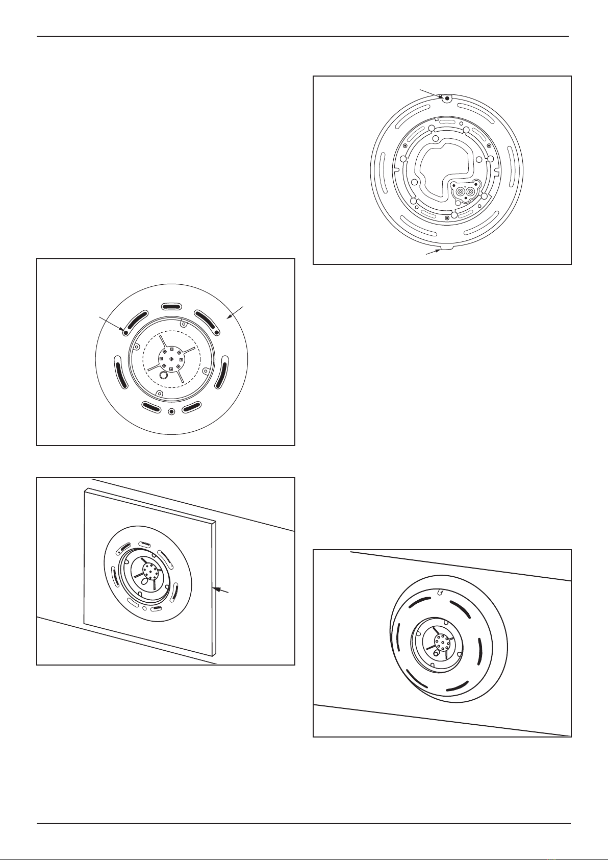
5.2 Flush Mount Installation
1. Remove the old light and flush mounting plate
from the pool wall. As LumiPower lights will fit
directly onto some existing mounting plates,
trial fit the LumiPower light to the mounting
plate.
If the light fits, then the old mounting plates
can be reused if they are in good condition. If
the existing mounting plate can’t be used, then
it can be used as a pattern to drill mounting
and cable holes in the LumiPower mounting
plate.
NOTE: DO NOT SUBMERGE the LumiPower light into
pool water unless it has the cable fitted.
2. Follow Section 4.2 instructions, which
will guide you through installing your new
Lumipower light.
3. Follow the steps in Section 5.3 to join the
LumiPower power cable to the existing power
cable.
4. Perform final installation of the LumiPower
light.
5.3 Lumipower 2.5m Cable Connection
1. If necessary, cut off the old connector from
the existing power cable. Trim the supplied
Lumipower power cable so that, once joined,
the new combined power cable has sufficient
length to be able to reach above the surface
of the water. This allows easier installation and
servicing. Excess cable can be removed if
desired.
2. Trim the ends of both of the cables to be
joined as shown. Note that if either cable has
solder on the cables this section should be cut
off so that the bare wires are exposed.
3. Ensure that the cables to be joined are clean
and dry in the area around the proposed joint.
If the cable isn’t clean, it may be possible to
trim the cable until a clean area is reached.
Otherwise, the cable can be lightly rubbed with
sandpaper to remove concrete residues etc.
20mm
5mm
Heat-shrink Tube
Heat-shrink Tube
Solder Splice
Heat Gun
Glue
Figure 7. Apply Heat-shrink Tube
4. Slide the heat-shrink tube onto the longest
cable and well away from the joint. This tube
has to be kept clear of the solder splices when
they are being heated. See Figure 7.
5. Fit one of the solder splices to each of the two
wires of the old cable. See Figure 8.
20mm
5mm
Heat-shrink Tube
Heat-shrink Tube
Solder Splice
Figure 8. Fit Solder Splice to Wire Ends
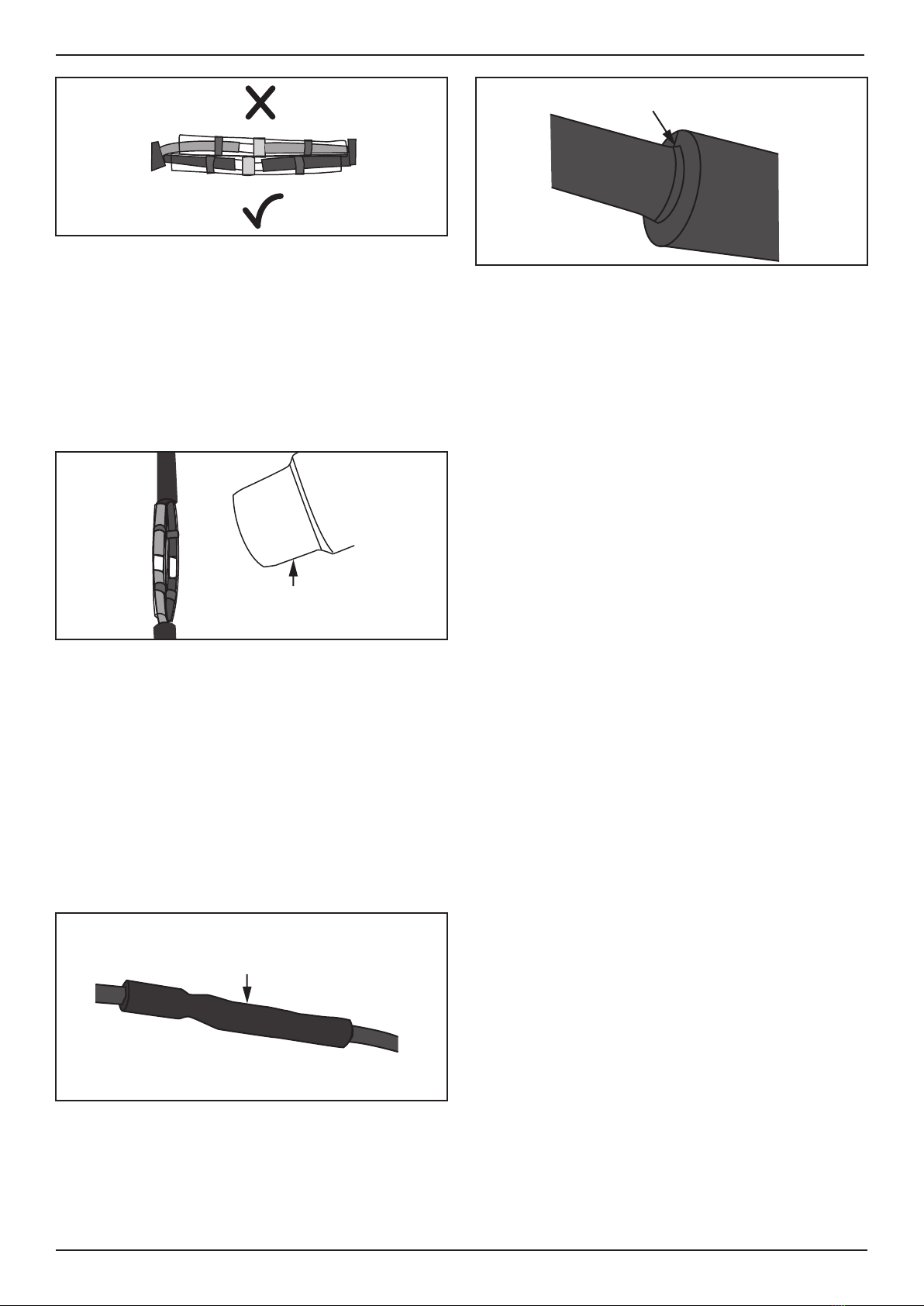
6. Slide the wires from the new cable into the
solder splices and position each splice so that
the silver coloured solder ball is positioned
over where the two (2) wires join. See Figure 9.