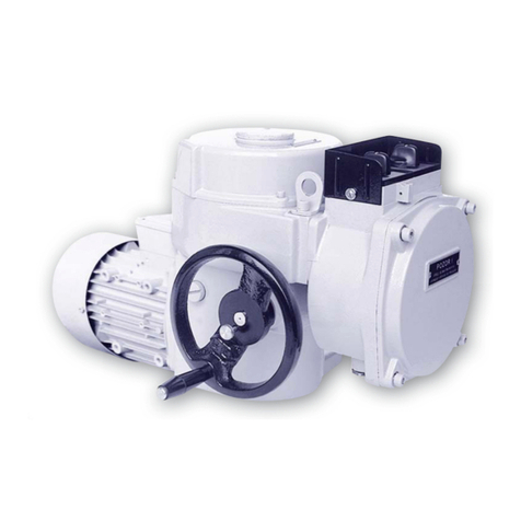
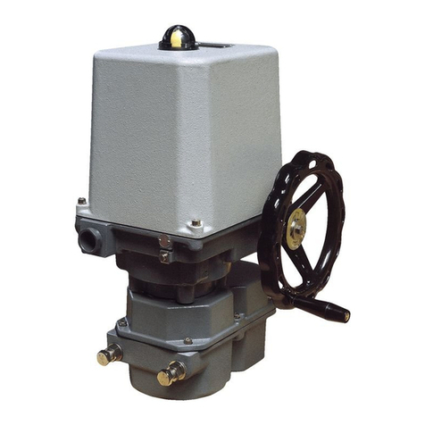
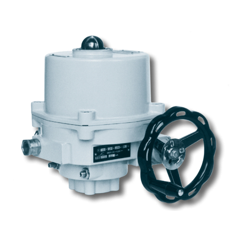
ZPA Pecky, a.s. MODACT MOED EEx Series Service manual

11/11
Type numbers 52 120 - 51 125
Electric rotary multi-turn actuators
Explosion-proof design
MOUNTING AND OPERATING
INSTRUCTIONS
INSTRUCTIONS


3
The Mounting and Operating Instructions specify basic principles for mounting, connection, adjustment, opera-
tion, maintenance, and repairs of electric explosion-proof actuators. A fundamental prerequisite is that assembly,
operation, maintenance, and revisions are performed by skilled technicians qualified for operation and works on
explosion-proof electric devices and the works are supervised by a professionally qualified expert instructed in
a demonstrable way.
1) APPLICATION
The MODACT MOED EEx electric rotary multi-turn actuators are specially intended for controlling devices
by a reversing rotary motion, e.g. slide valves and valves, and, in connection with an appropriate gearbox, also flap or
ball valves, and other devices for which they are suitable due to their properties.
They can be operated in an environment with a danger of explosion of explosive gaseous atmosphere in zone 1
and zone 2 according to ČSN EN 60079-10 (332320). The actuators are designed as a device of group II, category 2G
in compliance with standards ČSN EN 60079-0:2004, ČSN EN 60079-1:2004, and ČSN EN 60079-7:2004 for explo-
sive gaseous atmosphere.
The actuators are marked with a label of protection against explosion and symbols of the group and category
of the device II 2G.
– for surrounding temperature -25 °C to +55 °C: with marking Ex d IIC T4
– for surrounding temperature -50 °C to +55 °C: with marking Ex d IIB T4
Marking of actuators for surrounding temperature -50 °C to +55 °C is with the letter F at the 11th place of the type
number, i.e. 52 120.xxxxEDF. The electronic outfit of the version Ex d IIB T4 should be discussed with the manufacturer.
Nomenclature:
Environment with explosion danger – Environment in which an explosive atmosphere can be created
Explosive gaseous atmosphere –A mixture of flammable substances (in the form of gases, vapours or mist)
with air under atmospheric conditions in which, after initialization, burning
spreads out to non-consumed mixture.
Maximum surface temperature –
The highest temperature created during operation under the most unfavourable
conditions (however within approved limits) on any surface part of the electric
device, which could induce ignition of surrounding atmosphere.
Closure – All walls, doors, covers, cable bushings, shafts, rods, pull-rods, etc. which
contribute to the type of protection against explosion and/or to the level of
protection (IP) of the electric device.
Explosion-proof closure “d” – Type of protection in which the parts capable of causing ignition of
an explosive atmosphere are installed inside the closure; in case of internal
explosion this closure should withstand pressure of the explosion and pre-
vent spreading of the explosion into the surrounding atmosphere.
Zone 1 –
A space where probability of occurrence of an explosive atmosphere of
a mixture of flammable substances in the form of gas, vapour or mist with
the air is occasional under normal operation.
Zone 2
– A space where occurrence of an explosive gaseous atmosphere formed of
a mixture of flammable substances in the form of gas, vapour or mist with
the air is improbable under normal operation; however, if this atmosphere is
formed it will only persist for a short period of time.
Standards
The following basic standards apply to explosion-proof actuators:
ČSN EN 60079-0 Electrical devices for explosive gaseous atmosphere. General requirements.
ČSN EN 60079-1 Electrical devices for explosive gaseous atmosphere. Explosion-proof closure “d”.
ČSN EN 60079-10 Electrical devices for explosive gaseous atmosphere. Specification of dangerous areas.
ČSN EN 60079-14
Regulations for electrical devices in areas with a danger of explosion of flammable gases and
vapours.
ČSN IEC 60721 Types of environment for electrical devices.
ČSN 33 0371 Non-explosive mixtures. Classification and testing methods.
ČSN 34 3205 Operation of electric rotating machines and work with them.
4
Designation of explosion-proof properties
It consists of the following symbols:
Ex Electric device complies with the standard ČSN EN 60 079-0 and related standards for various
types of protection against explosion.
d
Designation of the type of protection against explosion, explosion-proof closure according to
ČSN EN 60 079-1.
II Designation of the group of explosion-proof electric device according to ČSN EN 60 079-0.
B, C
Designation of the sub-group of the group of explosion-proof electric device according to
ČSN EN 60 079-0.
T4 Designation of temperature class of explosion-proof electric device of the Group II according to ČSN
EN 60 079-0.
Data on actuators
The actuators are fitted with the following plates:
1) Plate with data of non-explosive closures
2) Instrument plate contains
– electrical data of power circuits (voltage and frequency, current and output of electric motor)
– electrical data of control circuit of micro-switches (voltage, current)
– position transmitter (resistance, voltage and/or current)
3) Rating plate contains
– manufacturer's name
– type designation of product (type number)
– serial number
– year of production
– rated value of tripping torque Nm
– rated speed of shifting 1/min
– rated working stroke rev.
– designation of protective enclosure of actuator IP
– weight of actuator kg
– mark of conformity CE
4) Warning plate
5) Plates on covers with marking of used protection against explosion
a) explosion-proof closure “d” of control box and terminal box without block of local control and display
or
or
250~
–
3A~0,3A

5
b) explosion-proof closure “d” of terminal box with block of local control and display
6) Plate with marked manufacturer and manufacturer's address.
2) OPERATING CONDITIONS, OPERATING POSITION
Operating conditions
the MODACT MOED EEx actuators should withstand the effect of operating conditions and external influences,
Classes AA7, AB7, AC1, AD5, AE5, AF2, AG2, AH2, AK2, AL2, AM2, AN2, AP3, BA4, BC3 and BE3N2, according to
ČSN Standard 33 2000-3.
When the actuator is installed on a free area it is recommended to fit it with a light shelter against direct impact of
atmospheric effects.The shelter should overlap the actuator contour by at least 10 cm at the height of 20 – 30 cm.
When the actuators are to be installed in a working environment with temperature below -10 °C and in an environment
with relative humidity above 80 %, it is always necessary to use an anti-condensation heater fitted to all actuators.
The electric actuators can be installed in areas with non-flammable and non-conductive dust, provided that this does
not adversely influence their function.Here, it is necessary to strictly observe ČSN 34 3205.It is recommended to remove
dust as soon as its layer is about 1 mm thick.
Classes of external influences
–as extracted from ČSN Standard 33 2000-3 (basic characteristics)
1) AA7 –
Simultaneous effect of ambient temperature of -25 °C to +55 °C (-50 °C to +55 °C) with relative
humidity from 10 % upwards
2) AB7 – Ambient temperature to Point 1); minimum relative humidity 10 %, maximum relative humidity 100 % with
condensation
3) AC1 – Altitude ≤ 2,000 m above sea level
4) AD5 – Splashing water in all directions
5) AE5 – Small dust content in air; medium layers of dust; daily dust fall out more than 35 mg/m2, but not exceeding
350 mg/m2
6) AF2 – Corroding atmosphere and pollutants; the presence of corroding pollutants is significant.
7) AG2 – Intermediate mechanical stress; in common industrial plants
8) AH2 – Medium vibrations; in common industrial plants
9) AK2 – Serious risk of growth of vegetation and moulds
10) AL2 – Serious danger of occurance of animals (insects, birds, small animals)
11) AM2 – Harmful effect of escaping vagabond currents
12) AN2 – Medium solar radiation with intensities > 500 W/m2and ≤ 700 W/m2
13) AP3 – Medium seismic effects; acceleration > 300 Gal ≤ 600 Gal
14) BA4 – Personal abilities; instructed staff
15) BC3 – Frequent contact with the earth potential; persons coming frequently into contat with “live” parts or standing
on a conducting base
16) BE3N2 –
Risk of explosion of combustible gases and vapours; according to ČSN EN 60079-10 (33 23 21), Zone 1.

6
Operating position
Working position of actuators MODACT®MOED EEx actuators with plastic lubricant – any position.
The actuators with plastic lubricant are labelled “Filled: solid grease” on the power box at the side of the hand-wheel.
Actuators with oil charge – position limited only by slope of electric motor axis – max. 15° under the
horizontal level. In this way, reducing of service life of rubber sealing of the electric motor shaft by possible
fragments or impurities from the oil filling is prevented.
When the actuator is assembled with the electric motor above the horizontal plane the oil filling should
be topped up so that reliable lubrication of the motor pinion is ensured.
The actuators with oil filling are not labeled.
3) OPERATION MODE, SERVICE LIFE OF ACTUATORS
Operation mode
According to ČSN EN 60 034-1, the electric actuators can be operated in the S2 load category. The run time at
temperature +50 °C is 10 min, the mean load torque is max. 60 % of the value of the maximum tripping torque Mv.
According to ČSN EN 60 034-1, the electric actuators can also be operated in S4 load category (interrupted
operation with starting-up).
The load factor N/N+R is max. 25 %; the longest operating cycle N+R is 10 min (the course of load is shown
in the picture). The maximum number of switching actions in automatic control mode is 1200 h-1. The mean load
torque with load factor 25 % and ambient temperature of 50 °C shall not exceed 40 % of the maximum tripping
torque Mv.
The highest mean load torque is equal to rated torque of the actuator.
Service life of actuators
Service life of actuators is 6 years, at the least.
The actuator intended for shut-off valves must be able to perform at least 10,000 operating cycles
(C - O - C).
The actuator intended for regulating purposes must be able to perform at least 1 million cycles with
operation time (during which the output shaft is moving) at least 250 hours. Service life in operating hours (h)
depends on load and number of switching. Not always, high frequency of switching influences positively
accuracy of regulation. For attaining the longest possible faultless period and service life, frequency of
switching is recommended to be set to the lowest number of switching necessary for the given process.
Orientation data of service life derived from the set regulation parameters are shown in the following table.
Service life of actuators for 1 million starts
Service life [h] 830 1 000 2 000 4 000
Number of starts [1/h] Max. number of starts 1200 1 000 500 250
Operating time
N
Idling time
R
Cycle period
Course of operating cycle
MzStarting torque ≥ 1.3 x Mv
Mstř Average load torque
MvMaximum tripping torque

7
4) TECHNICAL DATA
Supply voltage
The actuators have been designed to operate at supply voltage of 3 AC 400 V / 50 Hz. However, they are
available in design variants operating at another three-phase AC supply voltage, upon special request. The supply
voltage of the electric motor should be within the tolerance limits of ±10 % of the rated value and the supply voltage
frequency should be within ±2 % of the rated value. Within this supply voltage range, all parameters are kept
up except the starting torque which varies with the square of the supply voltage deviation from the rated value.
This dependence is directly proportional to the supply voltage variation; no larger supply voltage and frequency
fluctuations are permitted.
Protective enclosure
Protective enclosure of actuators MODACT MOED EEx – IP 55 according to ČSN EN 60 529
Noise
Level of acoustic pressure A max. 85 dB (A)
Level of acoustic output A max. 95 dB (A)
Tripping torque
Tripping torque is set at the manufacturer according to the customer's requirements within the range given in Table
No. 1, 2. If setting of tripping torque is not required maximum tripping torque of the required type number of the electric
actuator is set.
Starting torque
The starting torque of the actuator is a calculated value determined by the starting torque of the electric motor and
the total gear ratio and efficiency of the actuator. After run reversation, the actuator can produce a starting torque for
the duration of 1 to 2 revolutions of the output shaft when torque-limit switching is locked. This can take place in either
end position or in any intermediate position.
Self-locking
The actuator is self-locking provided that the load only acts in the direction against motion of the actuator
output shaft. Self-locking is ensured by a roller arrest immobilizing the electric motor rotor even in the case of
manual control.
In order to observe safety regulations, the actuators cannot be used for driving transportation lifting devices with
possible transport of persons or for installations where persons can stand under the lifted load.
Sense of rotation
When looking at the output shaft in the direction towards the control box, the CLOSE direction of rotation is identical
with the clockwise sense.
Working stroke
The ranges of working stroke are given in Table No. 1 or No. 2.
Rising spindle
In the design variants with connecting dimensions, Shapes A and C, the actuators can be adapted for mounting
to the valve with a rising spindle that projects over the upper end of the actuator output shaft in the end position of the
valve. The space reserved for the rising spindle is clearly shown in the dimensional sketches. The user should mount
a cylindrical guard of the rising spindle instead of the port cover at the control box top, if required. This guard has not
been included in the delivery of the actuator.
Manual control
Manual control is performed directly by a handwheel (without clutch). It can be used even when the electric
motor is running (the resulting motion of the output shaft is determined by the function of the differential gear). When
the handwheel is rotated clockwise the output shaft of the actuator also rotates clockwise (when looking at the shaft
towards the control box). On condition that the valve nut is provided with left-hand thread, the actuator closes the
valve.

8
5) ACTUATOR OUTFIT
Anti-condensation heater
The actuators are fitted with an anti-condensation heater preventing condensation of water vapour. It is connected
to the AC mains of voltage 230 V.
Local control
Local control serves for controlling the actuator from the site of its installation. It includes two change-over switches:
one with positions “Remote control - Off - Local control”, the other “Open - Stop - Close”.
The former change-over switch can be built-in as two-pole or four-pole. The change-over switches are installed in
a terminal-board box and the control elements on the lid of this terminal-board box.
6) ELECTRIC PARAMETERS
External electric connection
The electric actuator is equipped with a terminal board for connection to external circuits. This terminal board uses
screw terminals allowing conductors with a maximum cross-section 4 mm2to be connected. Access to the terminal
board is obtained after removal of the terminal box cover. All control circuits of the electric actuator are brought out to
the terminal board. The terminal box is fitted with cable bushings for connecting the electric actuator. The electric motor
is fitted with an independent box with a terminal board and a bushing.
Actuator internal wiring
The internal wiring diagrams of the MODACT MOED EEx actuators with terminal designation are shown
in this Mounting and operating instructions.
Each actuator is provided with its internal wiring diagram on the inner side of the terminal box. The terminals are
marked on a self-adhesive label attached to a carrying strip under the terminal block.
Isolation resistance
Isolation resistance of electric control circuits against the frame and against each other is min. 20 Mohm. After
a dump test, isolation resistance of control circuits is min. 2 Mohm. Isolation resistance of the electric motor is min.
1.9 Mohm. See Technical specifications for more details.
Electric strength of electric circuits isolation
Circuits of anti-condensation heater 1 500 V, 50 Hz
Electric motor Un = 3 x 230/400 V 1 800 V, 50 Hz
Deviations of basic parameters
Tripping torque ±12 % of max. value of range
Adjusting speed - 10 % of max. value of range
+15 % of rated value (idle run)
Protection
The actuators are fitted with one internal and one external protective terminals ensuring protection against electric
shock according to ČSN 33 2000-4-41. One protective terminal is also fitted to the electric motor. The protective
terminals are labelled with a mark according to ČSN EN 60417-1a2 (013760).
7) DESCRIPTION
The electric actuators are designed for direct attachment on the controlled device. (valve etc.). The actua-
tors are connected by means of a flange and a clutch according to ČSN 18 6314. The actuator flanges also
comply with ISO 5210. The following clutches are available for transmission of the output shaft motion to the
valve:

9
Shape A (with adapter), according to ISO 5210 and DIN 3210
Shape B1 (with adapter), according to ISO 5210 (shape B according to DIN 3210)
Shape B3 (without adapter), according to ISO 5210 (shape E according to DIN 3210)
Shape D (without adapter), according to DIN 3210
Shape C (without adapter), according to DIN 3338
The adapters are mounted between the actuator and the valve.
Moreover, the actuators can be delivered with connection according to Russian standards OCT (connection M, A,
Б, В, Г), see the version in table no. 3.
The electric actuator configuration is shown in Fig. 1. The three-phase asynchronous motor 1 drives, via the coun-
tershaft gearing 2, the sun gear of the differential gear unit installed in the actuator supporting box (power gearing) 3.
In the motor control mode, the crown gear of the planet differential unit is held in fixed position by a self-locking
worm gearing. The handwheel 4 connected with the worm allows manual control even when the motor is running. The
output hollow shaft is fix-connected to the driver of the planet gear and passes to the control box -5- where scanning
and control elements of the actuator are installed.
Operation of the torque-limit switching is derived from axial displacement of the “floating worm” of the manual con-
trol unit which is scanned and transferred to the control box by means of a lever. The control box forms an explosion-
proof closure “d” with designation Ex d IIC T4. The control elements are accessible after removing the cover 6
of this box. Access to the terminal box is possible after removing the cover 8.
The terminal board box also includes a firm closure “d” marked Ex d IIC T4. The cable inlets are secured by certi-
fied cable bushings HAWKE, type ICG 623, with a certificate; they can be used within the temperature range from
-60 °C to +80 °C. The bushings of the following sizes are used in the terminal board box:
cable ø
2 pieces ICG 623/B M25x1,5 13,0 – 20,2 mm Both cliental
2 pieces ICG 623/A M20x1,5 11,0 – 14,3 mm
One serves for interconnection with
the electric motor, the other is cliental.
The cable outlet system should meet the requirement of ČSN EN 60079-14 art. 10.3.2.d for direct inlet to the firm
closure of class IIC.
Therefore, in connecting the actuator, the client should provide for a non-explosive sealing (filling-in individual cable
wires) by means of the enclosed two-component filling-in putty according to the instructions.
ELECTRONIC OUTFIT
Electro-mechanical control board is replaced with the electronic system DMS2 or DMS2 ED. Both systems
scan position of the output shaft and torque of the electric actuator by contact-free magnetic sensors. Long
service life is guaranteed for the contact-free sensors that do not get mechanically worn.
Description:
1 – three-phase asynchronous motor
2 – countershaft gear box
3 – power gearing
4 – wheel of manual control
5 – control box
6 – control box cover
7 – terminal box
8 – terminal box cover
9 – cable bushings
10 – terminal board
11 – cable bushing for electric motor
Fig. 1 – Actuator set-up (actuators with DMS2 ED electronic system)
1234 9
11 10 5 6 7 8

10
The sensor of the output shaft position is absolute and does not require any backup power supply in case
supply voltage is disconnected during operation of the electric actuator. Both systems can be set and monitored
by a computer with controlling program (set parameter can be backed up on a computer) or manually without
a computer (for the electronics DMS2, parameters can be manually set and it can be checked without computer
only if the system is equipped with a display and local control). They contain diagnostic functions - error messages
on the display, memory of recent failures and number of occurrences of respective failures.
The more simple system DMS2 ED substitutes the electro-mechanical board and/or provides for controlling
the electric actuator by input analog signal as in the version Control.
The system DMS2 enables the electric actuator to be used for two-position and three-position regulation or
to be connected to the industrial bus bar Profibus.
DMS2 ED
Basic outfit:
Control unit main part of the system DMS2.ED - includes microcomputer, position sensor, 3 signal
lamps LED, 4 push-buttons for simple setting and checking the actuator, connectors for
connecting the torque sensor, source board, and interface RS 232 (connection of com-
puter for setting and diagnostics).
Torque unit
Source unit electronic power supply, user's terminal board (connection of power supply and control
signals), 2 torque relays, 2 position relays, 2 signalling relays, 1 relay for signalling errors
(READY), switch of resistance anti-condensation heater, connectors for connecting
electronic brake, resistance heater of analog module, and connector for interconnection
with the control unit.
Optional outfit:
Analog module output of feed-back signal 4 – 20 mA, in version CONTROL input of control signal
0/4 – 20 mA
Position indicator LED display
Local control
Contactors or contact-less block
Electronic brake
Parameters:
Scanning of position contact-less, magnetic
Scanning of torque contact-less, magnetic
Working stroke see Tables 1, 2, 3
Torque blocking 0 – 20 s at reversing in limit positions
Input signal 0 (4) – 20 mA with switched on regulator function
Local/Remote control, Local open/close
Output signal 7 x relay 250 V AC, 3 A (MO, MZ, PO, PZ, SO, SZ, READY)
Position signal 4 – 20 mA max. 500 ohm, active/passive, galvanic-isolated,
LED display, electronic brake control
Power supply of electronic 230 V AC, 50 Hz, 4 W, over-voltage category II
Realization:
Replacement of electric- the provided relay contacts substitute position, torque and signalling micro-switches;
mechanical board current feed-back signal 4 – 20 mA can also be brought out; the actuator is controlled by
the superior control system with signals “open” and “close”.
CONTROL The electronics covers also function of the regulator; the output shaft position is contro-
lled by analog input signal.
Function and setting of output relays
The output relays replace end-limit micro-switches; to some extent, function of the output relays differs according to
chosen mode of electronics or it can be selected, preferably by the setting program.

11
Relay MO, MZ, PO, PZ
In the version Control, the function of relay MO/MZ is same as that of motor relays.
Their operation is controlled by:
- regulation loop (deviation of required and actual position)
- active errors
Any induced active error will change over both relays to a standstill position (coils not energized). In case of errors,
the relays with a function of torque relays (in both versions DMS2 ED and DMS2 ED Control) are also controlled.
Relays SZ, SO, READY
Setting program
The setting program is same for communication with the electronics DMS2 ED and DMS2. The users' versi-
on can be freely downloaded.
Note: In the window “Parameters” of the setting program, column “Access”, the word “NO” designates parameters that
cannot be changed by the user (change of these parameters is blocked).
MO torque open
(also changes-over to errors) motor open
MZ torque closed
(also changes-over to errors) motor close
PO position open torque open (also changes-over to errors ) + optional
tripping in position open (parameter Tripping)
PZ position closed torque closed (also changes-over to errors ) + optional
tripping in position closed (parameter Tripping)
Relay DMS2 ED DMS2 ED Control
Relay READY
- It usually signalizes errors + warning + not remote,
it can be changed-over to any offered signalization
Relay 3/SZ
- It usually signalizes position closed, it can be chan-
ged-over to any offered signalization
Relay 4/SO
- It usually signalizes position open, it can be chan-
ged-over to any offered signalization
Relay 3/SZ Relay 4/SO
OFF
position O
position Z
torque O
torque Z
torque + position O
torque + position Z
opening
closing
motion
position
negated position
local control
remote control
control OFF
torgue O or Z
motion - blinker
Ready Relay
OFF
warning
errors
warning or errors
errors or no remote
errors or warning or no remote
torgue O or Z

12
PROCEDURE OF SETTING PARAMETERS BY MEANS OF PUSH-BUTTONS
For simple programming of required operating parameters, the control unit is fitted with four push-buttons:
MENU, P, O, C and three signal lamps.
Yellow Red Green State
- - - System without feeding
- - lit on Everything OK – working regime (remote, local or switched off control)
- blinking lit on Error or warning – working regime (remote, local or switched off control)
lit on - lit on Enter or exit of Setting of parameters by means of push-buttons
or Setting of parameters by means of PC
blinking - lit on
blinking blinking lit on Setting of parameters by means of push-buttons
blinking blinking lit on
In adjustment, follow the paragraphs “VERIFICATION of APPARATUS FUNCTION And its LOCATION”,
“fitting on VALVE” and “ADJUSTMENT of ACTUATOR with VALVE” of these instructions.
For safety reasons, the system is delivered in the state of induced error of Calibration when the functions are
limited in order to reduce the risk of damage to the actuator by wrong wiring.
Record of position CLOSED, OPEN and AUTOCALIBRATION
–
The actuator must be adjusted in such a way that the recorded position would switch off the actuator before it is switched
off by torque. For tight closure, the torque relay for torque Closed is only connected into the control circuit. The actuator
can be shifted either manually or electrically. The actuator in version CONTROL can be started from menu MOTOR in
program DMS2. In this case, the actuator does not react to the set position and can only be stopped by the torque relay.
In controlling from menu MOTOR, no torque may be induced. The torque must be left manually.
If, during adjustment, the torque is reached in the end-limit position, the torque must be left by means of a hand wheel.
– The actuator is set to position Closed and position Closed is stored by long pressing of push-button C (without
entering the Menu).
– The actuator is set to position Open and position Open is stored by long pressing of push-button O.
– The calibration routine is started by means of push-button P (in remote control) that, in the three-position regulati-
on, will measure actual inertial masses of the system and store them into the memory of the control unit. In the
two-position regulation, pressing of push-button P only cancels the error of Calibration.
– In recording the end-limit positions, signalling relays and the position transducer are also set.
–
In case the actuator stroke is to be increased and the switching off is set to “from position”, the actuator will switch off
during shifting in position O or 100 %. To further change the position, press C or O, and, while keeping it depressed, the
actuator can be further shifted. After required position is reached, it is stored to memory by pressing push-button C or O.
Parametr – Parameter
Změna – Change
Chyba – Error
Přístup – Access
Setrvačnost (0,1 %) – Inertia [0.1 %]
Setr. Doběh (0,1 s) – Inertial run-out [0.1 s]
Necitlivost (%) – Insensitivity [%]
NE – NO
¼ÈÆ ÉÈÐ¾Ë ÍÈËÄ
ºÂÇ
ž½ª ž½« ž½¬
ƾÇÎ Éȼ
Push-buttons and signal lamps LED on control unit DMS2.ED.S and DMS2.ED.S90
Colours of diodes:
LED1 – yellow (menu number)
LED2 – red (parameter value)
LED3 – green

13
Parameters that can be changed by user are set by manufacturer as follows:
1. Tripping torques: 100 % or required value (it is not recommended to change the value
without consulting the supplier of the valve, etc.).
2. Relay 3 and relay 4: signalization SZ 1 % and SO 99 % of stroke
3. Time of blocking: 2 – 8 s according to rate of actuator shifting
4. Position of blocking: 5 % of stroke from end-limit positions (it is not recommend to change
the value by more than 10 %)
5. Characteristics of position transducer: closed 4 mA, open 20 mA
6. Relay READY: errors + warning + not remote
In version CONTROL:
1. Setting of control signal: closed 4 mA, open 20 mA
2. Insensitivity of actuator in regulation: 1 % (it is not recommended to set insensitivity higher than 3 %)
3. Response in case of loss of control signal: stop
4. Way of switch off in end-limit positions: torque + PO + PZ
Overview of MENU
BROWSING THROUGH MENU
– The setting regime is entered by pressing and keeping depressed push-button MENU for at least 2 s; LED1 is then
lit on.
– Shortly press MENU to select the basic MENU – menu M1 to M8 (LED1 signalizes the menu number); by short
pressing of P, O, C they are entered (LED2 signalizes particular parameter).
– Shortly press P to select required value of the parameter. In case the parameter can be set to several values, they
are changed by short pressing of P (number of blinking of LED2 indicates its value). Keep pressing of P to record
the chosen parameter; the record is confirmed by lighting on of LED2.
– Shortly press MENU to gradually set the required menu and parameters.
– After setting all required parameters, exit the setting menu by pressing and keeping depressed push-button MENU
for at least 2 s. The setting menu will also be left in case that no push-button is pressed within 1 minute.
MENU 1 – Setting of tripping torques
– After entering the menu by means of push-button C or O, select required torque.
– Shortly press P to select the set value of the parameter 50 – 100 % (5 – 10 blinking of LED2) and keep pressing
push-button P to store the parameter to memory.
MENU 2 – Setting function of signalling relays
– Basic setting of the signalling relays is SZ 1 % and SO 99 % of stroke.
– n case different setting is required, it can be changed after shifting the actuator to required position by means of
push-button C or O.
– Using push-button P, perform basic setting SZ 1 % and SO 99 % of stroke.
MENU 3 – Setting of blocking of torque in end-limit positions
– Shortly press P to select the set value of blocking time 0 – 20 s (0 - 20 blinking of LED2) and keep pressing push-
-button P to store the parameter to memory.
– Keep pressing push-button C to store actual position for blocking torque on the side Closed to memory.
– Keep pressing push-button O to store actual position for blocking torque on the side Open to memory.
MENU 4 – Setting transducer characteristics
– Shortly press P to select the value 4 – 20 mA – 1x blinking of LED2 or 20 – 4 mA – 2x blinking of LED2, and keep
pressing push-button P to store the parameter to memory.
Other menus only serve for board setting in version Control
MENU 5 – Setting control signal in 3P regulation
– Shortly press P to select value 4 – 20 mA - 1x blinking of LED2,
or 20 – 4 mA - 2x blinking of LED2,
or 0 – 20 mA - 3x blinking of LED2,
or 20 – 0 mA - 4x blinking of LED2
and keep pressing push-button P to store the parameter to memory.

14
MENU 6 – Setting insensitivity in three-position regulation
– Shortly press P to select value 1 – 10 % (1 – 10x blinking of LED2) and keep pressing push-button P to store the
parameter to memory.
MENU 7 – Response in case of losing control signal in three-position regulation
– Shortly press P to select value OPEN - 1x blinking of LED2,
or CLOSE - 2x blinking of LED2,
or STOP - 3x blinking of LED2,
and keep pressing push-button P to store the parameter to memory.
MENU 8 – Way of switching off in end-limit positions in 3P regulation
– Shortly press P to select value TORQUE - 1x blinking of LED2,
or TORQUE + PO - 2x blinking of LED2,
or TORQUE + PZ - 3x blinking of LED2,
TORQUE + PO + PZ - 4x blinking of LED2,
And keep pressing push-button P to store the parameter to memory.
PROCEDURE OF SETTING PARAMETERS BY PROGRAM DMS2
– Before starting the actuator, it is necessary to set some parameters of the system by means of program
DMS2 on PC.
– For safety reasons, the system is delivered in the state of induced error of Calibration when the functions are limited
in order to reduce the risk of damaging the actuator by wrong wiring. In controlling the actuator from program DMS2,
its run is stopped when any torque is induced.
Working torque
– Check and, if necessary, set the value of working torque 50 – 100 % in program DMS2.
Record of positions OPEN, CLOSED and AUTOCALIBRATION
The actuator should be adjusted so that the recorded position would stop the actuator before it is switched
off by torque. The actuator is shifted manually or electrically. The actuator in version CONTROL can be started
from menu MOTOR in program DMS2. In this case, the actuator does not respond to the set position and is
switched off by torque. In controlling from menu MOTOR, no torque may be induced. The torque should be left
manually.
Main window of setting program Selection of electronics

15
Terminal board of actuator with electronics DMS2ED.
If the actuator is of the single-phase version the power supply is connected only to terminals PE, N, U. The terminals
V, W remain non-connected. If the actuator is of the version “Replacement of electric-mechanical board” with three-phase
electric motor without power relays, the electric motor is connected to a separate terminal board (not shown here).
Record of position CLOSED:
– In the required position, press push-button Z in the program and confirm the approved record.
Record of position OPEN:
– In the required position, press push-button O in the program and confirm the approved record.
The recorded values are confirmed by pressing push-button START in program DMS2. For the actuator in version
CONTROL, change over the actuator to remote control and, by pressing push-button START, start the autocalibration.
By short starting of the motor in both directions, the actuator measures inertia and changes over to the regulating
regime. Information on the course of autocalibration is signalized next to push-button START. The autocalibration
cannot be started in case the torque relay is switched off.The torque should be left manually.
Other parameters
Check and, if necessary, change other parameters:
Control signal 4 – 20 mA, 20 – 4 mA, 0 – 20 mA, 20 – 0 mA
Insensitivity 1 – 10 %
Function in case of error open, close, stop, to position
Time of torque blocking in end-limit positions 0 – 20 s
Position of torque blocking in end-limit positions 1 – 10 %
Output of position signal 4 – 20 mA, 20 – 4 mA
Function READY combined error
Note: Signal READY is brought out as contact of the relay on the terminal board. If the state ERROR or WAR-
NING is not detected (setting can be made of what is to be evaluated as error or warning), the contact is clo-
sed; in case of error, warning, or if feeding of electronics is interrupted, the contact is opened. The state of the
relay READY is indicated by the LED diode on the source board.
AUTODIAGNOSTICS
DMS2.ED performs continuously its diagnostics and, if a problem is detected, it reports warning or error.The warning
or error is signalized by LED of the display and, possibly, by relay Ready. The warning has no effect on operation of the
system, the error stops the actuator.
Assigning or switching off of warnings and errors is set in window “Warning and error” of the setting program (it is
opened by clicking one of parameters Warning 1 – 4 or Error 1 – 4 in window “Parameters”).
The error or warning are reported by opening the relay READY and by blinking of the red LED diode on the control
unit. Particular error is specified by program DMS2 or on the display.
RESTORING PARAMETERS FROM BACKUP
With the feeding switched off, press push-buttons O and C at the same time. Then, switch on feeding and wait until
red and yellow LED diodes light on.The backup parameters are read.

16
List of warnings and errors
No. Name Warning1Error1Description
1 Safe * X Input Safe activated
2 Control signal X Value of control signal ≤ 3 mA (it applies to ranges 4 – 20/20 – 4 mA)
4 Torque X Induced torque beyond end-limit positions or disconnected torque sensor
6 Thermal protection X Thermal protection input activated
7 Sense of rotation X Reverse sense of rotation (for CONTROL only)
8 EEPROM X Wrong control sum of parameters in EEPROM
9 RAM X Wrong control sum of parameters in RAM
10 Parameters X Wrong parameters in EEPROM
11 Setting regimes X Setting regime from push-buttons or PC
12 Torque sensor X Disconnected or defective torque sensor
13 Sensor 1 X Error of sensor of position 1 (lowest stage)
14 Sensor 2 X Error of sensor of position 2
15 Sensor 3 X Error of sensor of position 3
16 Sensor 4 X Error of sensor of position 4 (highest stage)
17 Calibration X Autocalibration not carried out
18 Torque setting X Wrong setting of torques (parameters Torque O/Z 50/100 %)
19 Stroke X Wrong setting of stroke (parameters Position O/Z)
21 High temperature X Permitted max. temperature exceeded (parameter Temperature max.)
22 Low temperature X Permitted min. temperature exceeded (parameter Temperature min.)
23 LCD internal * X Display of LCD internal does not communicate or not added
in parameter CAN of configuration
24 LCD external * X Display of LCD external does not communicate or not added
in parameter CAN of configuration
25 Fieldbus * X Module of industrial bus does not communicate or not added
in parameter CAN of configuration
26 CAN * X Error of bus CAN (short circuit, interruption, only sensor communicates)
27 Fieldbus activity* X Connection to industrial bus not active
28 Phase * X Inverse order of phases or some phase missing
29 Relay of service life X Service life of relay MO/MZ at CONTROL exceeded
(parameter Relay of service life)
30 Reset X Non-standard Reset of unit induced (watchdog etc.)
31 ROM X Wrong control sum of program in ROM
32 CAN version * X Sensor, LCD display or module Fieldbus have incompatible
versions of firmware
33 Wrong command * X Commands Open and Close entered at the same time
34 Wrong inertia - - Wrong inertia measured by autocalibration (for autocalibration only)
35 Wrong run-down - - Wrong run-down measured by autocalibration (for autocalibration only)
41 Wrong position X Servo-drive is in position 25 % behind working stroke
1)Assignment can vary depending on the version of firmware of the sensor control unit.
* Applies to DMS2 only.
Memory of number of induced warnings and errors
– For all ascertained warnings and errors, DMS2.ED uses counters of occurrence of these warnings and errors during
operation of the system.
– Values of the counters are stored to the EEPROM memory and are preserved even in case of the power supply fall-out.
– Reading of the counters is possible by means of the program for PC
– Clearing of the counters is possible by means of the program for PC with the level of authorization “SERVICE”.
Memory of recently induced warnings and errors
– DMS2.ED stores three recently induced warnings and errors to the EEPROM memory.
– Recent warnings and errors can be displayed and erased by means of the program for PC.

17
PE
PE Zdrojová deska
Snímač
momentu
Snímač
OCPMENU
MO 10
2
1
COM 20
U
SZ
SO
24
21
22
18
23
T.P.
MI/DAL
PO 16
PZ 19
15
4
17
MZ 12
3
13
11
RUOR +5V
READY
6
5
TOP
1
2
N
8
7
N
F160mA
V
W
N
polohy
2x
-L
COMM
Analogový modul
+L
mA
Pasívní výstup
Aktivní výstup
Dálkové povoleno
Dálkov
é
Dálkov
é
V provedení bez místního
ovládání se propojka
ze svorky U zapojí na svorku 2
"otevír
e
"zavírej
"
Místní
ovládání
DAL MI
VYP
OZ
873
(2)
1
OTV ZAV
STOP
DM
(6)
54
zavírej
motor
otevírej
motor
T.P.
Síť přívod
E0021
Wiring diagram of electronics DMS2 ED in version
Substitution of electro-mechanical board
E0021
Note: Here, contacts of relays MO, MZ, SO, SZ are shown with power supply switched off; with power supply switched off contacts PO,
PZ are shifted to the position drawn in dashed line.
Position
sensor
Torque
sensor
Local control
Passive output
Active output
Analog module
Source board
In version without local control,
the jumper from terminal U
is connected to terminal 2
off local
remote
CLOSE
STOP
Remote
Motor
Motor
Remote
“close”
“close”
“open”
“open”
Remote permitted
Mains supply
OPEN

18
Wiring diagram of electronics DMS2 ED in version Substitution of electro-mechanical board with block of contactors
3
5
1
6
4
2
A1A2
A1A2
KZ KO
3
5
1
6
4
2
PE
PE Zdrojová deska
Snímač
momentu
Snímač
OCPMENU
MO 10
2
1
COM 20
U
SZ
SO
24
21
22
18
23
T.P.
MI/DAL
PO 16
PZ 19
15
4
17
MZ 12
3
13
11
RUOR +5V
READY
6
5
TOP
1
2
N
8
7
N
U
F160mA
VV
WW
NN
polohy
2x
-L
COMM
Analogový modul
+L
mA
Pasívní výstup
Aktivní výstup
3x400V
Dálkové povoleno
Dálkové
Dálkové
M3~
U1
W1
V1
E0022
V provedení bez místního
ovládání se propojka
ze svorky U zapojí na svorku 2
"otevírej"
"zavírej"
873
(2)
1
(6)
54
Místní ovládání
DAL MI
VYP
OZ
OTV ZAV
STOP
DME0022
Note: Here, contacts of relays MO, MZ, SO, SZ are shown with power supply switched off; with power supply switched off contacts PO, PZ are shifted to the position drawn in dashed line.
Position
sensor
Torque
sensor
Local control
Passive output
Active output
Analog module
Source board
In version without local control,
the jumper from terminal U
is connected to terminal 2
off localremote
CLOSE
STOP
OPEN
Remote
Remote
“close”
“open”
Remote permitted

19
4
2 1 3
3
5
1
6
4
2
A1A2
2122
A1A2
M3~
KZ KO
3
5
1
6
4
2
2122
PE
PE Zdrojová deska
Snímač
momentu
Snímač
OCPMENU
MO 10
2
1
COM 20
U
SZ
SO
24
21
22
18
23
T.P.
MI/DAL
PO 16
PZ 19
15
4
17
MZ 12
3
13
11
RUOR +5V
READY
6
5
TOP
1
2
N
8
7
N
U
F160mA
VV
WW
NN
polohy
2x
PE
+IN
-IN
-L
COMM
Analogový modul
+L
mA
Pasívní výstup
Aktivní výstup
4÷20mA
3x400V U2
W2
V2
U1
W1
V1
TH
E0023
V provedení bez místního
ovládání se propojka ze
svorky U zapojí na svorku 2
Místní ovládání
DAL MI
VYP
OTV ZAV
STOP
873
(2)
1
(6)
54
OZ
DM
Wiring diagram of electronics DMS2 ED in version Control with
three-phase electric motor
E0023
Note: Here, contacts of relays MO, MZ, SO, SZ are shown with power supply switched off; with power supply switched off contacts PO, PZ are shifted to the position drawn in dashed line.
Local control
Passive output
Active output
Analog module
Source board
Torque
sensor
Position
sensor
In version without local control,
the jumper from terminal U
is connected to terminal 2
off localremote
CLOSE
STOP
OPEN

20
DMS2
Main properties of DMS2:
–
Complete control of the actuator run of the two- and three-position regulation or connection to the industrial bus Profibus.
– Synoptic signalization of operation and service data on the character LCD display 2 x 12.
– Autodiagnostics of error reports on the LCD display, memory of recent failures and number of occurrences of
respective failures.
– Setting of parameters by the PC program and by local control provided that the actuator is fitted with local control.
Basic outfit:
The control unit is the main part of the system DMS2; it comprises:
– Microcomputer and memory of parameters
– Position sensors
– 2 signalling LED
– Connectors for connecting the torque sensor, relay board, and two-position inputs, source board, communication
adapter, LCD display, and local control
Torque unit provides for scanning torque by the contactless sensor
Source unit - two types exist:
DMS2.ZAN for the two-position or three-position control of the actuator by binary signals “Open” and “Close” or by
analog signal 0 (4) – 20 mA.
DMS2.ZPR for controlling the actuator by the industrial bus Profibus.
Both units include the feeding source for electronics, two relays for controlling the power switches (contactors or
contactless switches) of the electric motor, guarding of sequence of phases (in case the actuator is fed by three-phase
voltage), circuits for connecting the anticondensation heater, and input terminals for connecting the thermo-contact
from the electric motor. The units are fitted with the power terminal board for connecting the power supply. The units
are fitted with a connector for the display and local control.
Unit DMS2ZAN also contains:
– input circuits for the two-position and three-position control of the actuator and terminals for connecting external
control signals
– input of signal SAFE – information on external failure
– relay – total of five; four (signalling) can be set for reporting of position, torque, or other operation states of the
actuator; the fifth (Ready) is used for reporting of errors, warnings, and other states when the actuator cannot fault-
lessly perform its function, and the terminals to which contacts of the relay are connected
– circuits of the feedback current signal – information on position of the actuator output shaft
Unit DMS2.ZPR also contains:
– circuits for communication with the superior control system through the industrial bus Profibus DP, input and output
terminals for connecting the bus, and termination resistors with a switch.
Display unit – two-row display, 2 x 12 alpha-numeric characters
Unit of push-buttons – sensors of push-buttons “open”, “close”, “stop” and the rotary switch “local, remote, stop”.
The actuator can be fitted with contactors or contactless switching of the electric motor; it can be fitted with
an electronic brake.
PROCEDURE OF SETTING PARAMETERS BY PROGRAM DMS2
Before putting the actuator into operation, it is necessary to set some parameters of the system by means of pro-
gram DMS2 on PC.
Before adjustment, check the actuator according to the paragraph ASSEMBLing And putting the ACTUATOR into operation.
Warning:
For safety reasons (reduced risk of damage to the actuator by wrong wiring), the system is delivered in the state of
the induced error of CALIBRATION when the functions are limited and, during controlling the actuator from program
DMS2, its run is stopped if any torque is induced.
Note:
The setting program is the same for electronics DMS2 ED. See the figure on page 14 for the main window and the
window of Selection of electronics.
This manual suits for next models
55
Table of contents
Other ZPA Pecky, a.s. Controllers manuals

ZPA Pecky, a.s.
ZPA Pecky, a.s. MODACT MOA User manual

ZPA Pecky, a.s.
ZPA Pecky, a.s. MODACT MTNED Series User manual

ZPA Pecky, a.s.
ZPA Pecky, a.s. MODACT MO EE Series Service manual

ZPA Pecky, a.s.
ZPA Pecky, a.s. MODACT MOKPED 100 Ex User manual

ZPA Pecky, a.s.
ZPA Pecky, a.s. MODACT MOK 125 User manual

ZPA Pecky, a.s.
ZPA Pecky, a.s. MODACT MONEDJ User manual

ZPA Pecky, a.s.
ZPA Pecky, a.s. Modact MOKP Ex Series Installation instructions

ZPA Pecky, a.s.
ZPA Pecky, a.s. MODACT MTN User manual

ZPA Pecky, a.s.
ZPA Pecky, a.s. MODACT MON 52 030 User manual